EP1452269A1 - Werkzeugkopf für Werkzeugmaschinen oder Bearbeitungszentren sowie Maschine mit einem solchen Werkzeugkopf - Google Patents
Werkzeugkopf für Werkzeugmaschinen oder Bearbeitungszentren sowie Maschine mit einem solchen Werkzeugkopf Download PDFInfo
- Publication number
- EP1452269A1 EP1452269A1 EP03425117A EP03425117A EP1452269A1 EP 1452269 A1 EP1452269 A1 EP 1452269A1 EP 03425117 A EP03425117 A EP 03425117A EP 03425117 A EP03425117 A EP 03425117A EP 1452269 A1 EP1452269 A1 EP 1452269A1
- Authority
- EP
- European Patent Office
- Prior art keywords
- toolhead
- chucks
- numerically controlled
- chuck
- axis
- Prior art date
- Legal status (The legal status is an assumption and is not a legal conclusion. Google has not performed a legal analysis and makes no representation as to the accuracy of the status listed.)
- Withdrawn
Links
Images


Classifications
-
- B—PERFORMING OPERATIONS; TRANSPORTING
- B23—MACHINE TOOLS; METAL-WORKING NOT OTHERWISE PROVIDED FOR
- B23Q—DETAILS, COMPONENTS, OR ACCESSORIES FOR MACHINE TOOLS, e.g. ARRANGEMENTS FOR COPYING OR CONTROLLING; MACHINE TOOLS IN GENERAL CHARACTERISED BY THE CONSTRUCTION OF PARTICULAR DETAILS OR COMPONENTS; COMBINATIONS OR ASSOCIATIONS OF METAL-WORKING MACHINES, NOT DIRECTED TO A PARTICULAR RESULT
- B23Q39/00—Metal-working machines incorporating a plurality of sub-assemblies, each capable of performing a metal-working operation
- B23Q39/02—Metal-working machines incorporating a plurality of sub-assemblies, each capable of performing a metal-working operation the sub-assemblies being capable of being brought to act at a single operating station
- B23Q39/021—Metal-working machines incorporating a plurality of sub-assemblies, each capable of performing a metal-working operation the sub-assemblies being capable of being brought to act at a single operating station with a plurality of toolheads per workholder, whereby the toolhead is a main spindle, a multispindle, a revolver or the like
-
- B—PERFORMING OPERATIONS; TRANSPORTING
- B23—MACHINE TOOLS; METAL-WORKING NOT OTHERWISE PROVIDED FOR
- B23Q—DETAILS, COMPONENTS, OR ACCESSORIES FOR MACHINE TOOLS, e.g. ARRANGEMENTS FOR COPYING OR CONTROLLING; MACHINE TOOLS IN GENERAL CHARACTERISED BY THE CONSTRUCTION OF PARTICULAR DETAILS OR COMPONENTS; COMBINATIONS OR ASSOCIATIONS OF METAL-WORKING MACHINES, NOT DIRECTED TO A PARTICULAR RESULT
- B23Q1/00—Members which are comprised in the general build-up of a form of machine, particularly relatively large fixed members
- B23Q1/25—Movable or adjustable work or tool supports
- B23Q1/44—Movable or adjustable work or tool supports using particular mechanisms
- B23Q1/50—Movable or adjustable work or tool supports using particular mechanisms with rotating pairs only, the rotating pairs being the first two elements of the mechanism
- B23Q1/54—Movable or adjustable work or tool supports using particular mechanisms with rotating pairs only, the rotating pairs being the first two elements of the mechanism two rotating pairs only
- B23Q1/5468—Movable or adjustable work or tool supports using particular mechanisms with rotating pairs only, the rotating pairs being the first two elements of the mechanism two rotating pairs only a single rotating pair followed parallelly by a single rotating pair
- B23Q1/5475—Movable or adjustable work or tool supports using particular mechanisms with rotating pairs only, the rotating pairs being the first two elements of the mechanism two rotating pairs only a single rotating pair followed parallelly by a single rotating pair followed perpendicularly by a single rotating pair
-
- B—PERFORMING OPERATIONS; TRANSPORTING
- B23—MACHINE TOOLS; METAL-WORKING NOT OTHERWISE PROVIDED FOR
- B23Q—DETAILS, COMPONENTS, OR ACCESSORIES FOR MACHINE TOOLS, e.g. ARRANGEMENTS FOR COPYING OR CONTROLLING; MACHINE TOOLS IN GENERAL CHARACTERISED BY THE CONSTRUCTION OF PARTICULAR DETAILS OR COMPONENTS; COMBINATIONS OR ASSOCIATIONS OF METAL-WORKING MACHINES, NOT DIRECTED TO A PARTICULAR RESULT
- B23Q39/00—Metal-working machines incorporating a plurality of sub-assemblies, each capable of performing a metal-working operation
- B23Q2039/004—Machines with tool turrets
-
- B—PERFORMING OPERATIONS; TRANSPORTING
- B23—MACHINE TOOLS; METAL-WORKING NOT OTHERWISE PROVIDED FOR
- B23Q—DETAILS, COMPONENTS, OR ACCESSORIES FOR MACHINE TOOLS, e.g. ARRANGEMENTS FOR COPYING OR CONTROLLING; MACHINE TOOLS IN GENERAL CHARACTERISED BY THE CONSTRUCTION OF PARTICULAR DETAILS OR COMPONENTS; COMBINATIONS OR ASSOCIATIONS OF METAL-WORKING MACHINES, NOT DIRECTED TO A PARTICULAR RESULT
- B23Q2220/00—Machine tool components
- B23Q2220/006—Spindle heads
Definitions
- the present invention relates to a toolhead for a numerically controlled machine or work center.
- the invention relates to a so-called double-rotating head, that is able to perform rotating or oscillating movements around two numerically controlled axes, generally perpendicular to each other.
- the invention also relates to a machine tool or work center comprising a type of head of this type.
- machine tool and work center are utilized as synonyms.
- the invention relates to toolheads and relative machine tools or work centers intended in particular for the machining of wood.
- numerically controlled machine tools or work centers comprising a toolhead equipped with one or more chucks which may move around two numerically controlled axes of oscillation or rotation.
- machines or work centers of this type are described in EP-A-0744244, EP-A-0873317 and EP-A-1002620.
- These machines may have an upright along which a slide carrying the double-rotating head translates vertically, or in some cases a portal structure, with two uprights and a horizontal crosspiece, along which the slide supporting the double-rotating head translates.
- the double-rotating head carries four chucks in a cross arrangement, or in certain cases two chucks positioned opposite each other, with aligned axes.
- Machine tools of this type today require ever-increasing characteristics of flexibility and machining speed.
- the use of double-rotating heads with a large number of chucks makes it possible to have numerous tools available to machine a single workpiece.
- having for example four chucks and four corresponding tools in a cross arrangement sets some limits and causes some drawbacks, especially in machines with a portal structure.
- the object of the present invention is to produce a head and a machine tool employing said head which overcome the drawbacks and limits of traditional heads and relative machines or work centers.
- a toolhead comprising a plurality of chucks for corresponding machining tools, provided with a numerically controlled rotating or oscillating movement, characterized in that said chucks are divided into at least two assemblies, which move independently from each other around a first and a second numerically controlled axis of rotation or oscillation independent from each other.
- the double-rotating head according to the invention may even comprise double the number of chucks and therefore of tools. This allows, without an automatic tool loader and a tool magazine being required, numerous and different machining operations to be performed on the same workpiece, increasing productivity.
- At least one of the two assemblies of tools may also comprise a limited number of chucks, for example even a single chuck.
- advantages in terms of machining flexibility are, in any case, obtained.
- the head is of the double-rotating type, that is it has a third numerically controlled axis of rotation or oscillation.
- the movement of the two assemblies of tools around this third axis is simultaneous, as it is a numerically controlled axis common to the two assemblies of tools.
- the toolhead comprises a support - preferably oscillating or rotating around the third axis of rotation or oscillation, when present - which carries the two chuck assemblies, in turn rotating or oscillating in relation to the support around said first and second numerically controlled axes.
- each of the two chuck assemblies is supported by a respective arm anchored to the support.
- the two arms which advantageously may be parallel to each other, carry the respective chuck assemblies facing each other.
- the configuration of the head will therefore be a U or C, with the two chuck assemblies arranged inside the U or the C. It is also possible to arrange the chuck assemblies on the outside of the U or C structure formed by the support and by the arms.
- the two supporting arms of the two chuck assemblies may be mounted fixed on the support, in which case the two chuck assemblies are at a fixed distance from each other. Nonetheless, according to a preferred embodiment of the invention, the distance between the arms may be modified. For this purpose at least one of the two arms must be movable in relation to the support. The reciprocal distance between the two arms may be adjusted manually from time to time providing alternative clamping positions of the arm(s) movable in relation to the support. Preferably, nonetheless, the arms (or at least one of them) are movable along guides integral with the support, so that is possible to adjust the reciprocal distance of the chuck assemblies in any position and without discontinuity.
- the distance may be adjusted manually.
- actuators are preferably provided to allow this position to be adjusted automatically, even during the machine cycle according to the positioning requirements of the tools.
- a further numerically controlled axis may be provided for relative movement of one arm in relation to the other, although for reasons of simplicity and economy more simple operation is preferable, as precise modification of the reciprocal distance between the chuck assemblies is not required, two or more reciprocal alternative positions being sufficient.
- At least a first of said two chuck assemblies has a number of chucks equal to or less than three.
- These three chucks are arranged so as to leave a wide zone free around the axis of rotation or oscillation of the chuck assembly.
- the axes of the chucks may be arranged to form an area with an angular aperture of 180° without obstructions. This configuration is particularly advantageous, especially in machine tools with a portal structure.
- the first chuck assembly comprises three chucks and the second chuck assembly comprises four chucks.
- This configuration is a compromise between the need for a high number of chucks and thus tools and to prevent collisions with workpieces being machined or with parts of the machine structure, also comprising the mechanical components required to support and clamp workpieces.
- each chuck assembly may carry only two chucks or three chucks.
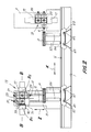
- Figs. 1, 1 A, 1 B and 2 show a first possible configuration of a machine tool mounting a double-rotating toolhead according to the invention.
- the machine tool indicated as a whole with 1, has a structure with a vertical upright 3 sliding along a pair of guides 5 carried by a first bed 7 which extends according to a direction X.
- This direction also represents the numerically controlled axis along which the upright 3 moves to perform one of the numerically controlled movements with which the machine is provided.
- the slide 11 supports a double-rotating toolhead indicated as a whole with 13.
- the double-rotating head 13 is provided with a numerically controlled rotating movement around a horizontal axis C, orthogonal to the axis X. It has a U or C structure, with a main support 15 from which two arms 17 and 19 extend projectingly parallel to the axis C. The unit formed by the support 15 and the arms 17, 19 rotates integrally around the axis of rotation C.
- the arm 17 supports a first chuck assembly 23, indicated as a whole with 21 which comprises, in the example shown (as can be seen in particular in Fig. 1A), four chucks 23 with a cross arrangement. Each chuck may carry its own tool.
- a single tool U is shown mounted on one of the four chucks 23 of the assembly 21.
- the assembly 21 of chucks 23 may rotate around a numerically controlled axis of rotation B1.
- the axis of rotation B1 is orthogonal to the axis of rotation C and (in the position shown in Fig.1) has a vertical direction. Rotation of the assembly 21 of chucks 23 around the axis of rotation B1 is imparted by an actuator 25, for example a brushless motor, by means of a toothed belt 27 or any other suitable mechanical drive component.
- the arm 19 supports a second chuck assembly indicated as a whole with 31.
- This second chuck assembly (as can be seen in particular in the view in Fig. IB-IB) comprises three chucks 33 arranged with their axes positioned at 90° in relation to one another.
- An actuator 35 analogous to the actuator 25, controls the rotating movement of the assembly 21 of chucks 33 around a second numerically, controlled axis of rotation indicated with B2. Also in this case the movement is transmitted by a flexible component, such as a belt 37 or the like.
- the two numerically controlled axes B1 and B2 are geometrically coincident with each other, that is the two chuck assemblies have the same geometric axis of rotation, indicated in the drawings with B-B.
- the numerically controlled axes B1 and B2 of rotation may also be positioned parallel to each other, but staggered.
- the two chuck assemblies 21, 31 rotate around axes that are geometrically parallel but staggered rather than around a common geometric axis.
- the two numerically controlled axes B1 and B2 may also not be parallel with each other.
- the two tool assemblies 21, 23 rotate around convergent or divergent geometric axes.
- the two chuck assemblies 21 and 31 rotate or oscillate around their respective axes B1 and B2 independently from each other, controlled by the two independent actuators 25 and 35.
- a carriage or slide 51 runs on the guides 47, provided with a numerically controlled movement along the numerically controlled axis Y.
- a carriage or slide 53 analogous to the carriage or slide 51 may travel along the guides 49 with a numerically controlled movement along the corresponding numerically controlled axis Y.
- Fig. 1 shows, with a solid line and a dashed line, two end positions which may be adopted by the carriage 53 movable along the guides 49.
- the carriages 51 and 53 carry the supporting and clamping means, generically and schematically indicated with 55 and 57, to support and clamp the workpieces to be machined, indicated summarily with P.
- the supporting means 55 and 57 have distances between centers that can be varied by providing specific guides 52 and 54 on the slides or carriages 51 and 53 respectively. This allows the surface on which workpieces are supported, composed of means 55 and 57, to be adapted to the dimension and shapes of the workpieces.
- the head 13, rotating around the axis C, allows the various tools mounted on the chucks 21 and 31 to be taken to the operating position.
- By providing a number of chucks of less than four for the assembly 31 of chucks 33 it is possible (while maintaining the advantage of an overall high number of chucks on the head 13), simply and without specific relative movements between workpiece being machined and the toolhead, to prevent collision between the workpiece being machined and tools which are not being utilized.
- the chuck 23 facing downward and belonging to the chuck assembly 21 may easily machine any point on the workpiece below it being machined without interference between said workpiece and the chucks 33 of the adjacent chuck assembly 31. This is possible as the second chuck assembly has been positioned so that none of the tools carried by the three chucks 33 are facing the workpiece being machined.
- the machine described hereinbefore is substantial provided with six numerically controlled axes: two axes of oscillation or rotation B1, B2, one for each chuck assembly 21, 31; one axis of oscillation or rotation C and three axes of translation X, Y, Z.
- the presence of two slides or carriages 51 and 53, which may translate along double axis Y, allows the machine to work in an oscillating cycle, that is to carry one of the two slides with the workpiece(s) to the machining position, in the operating area of the toolhead 13 and the other to a loading and unloading position, far from the machining area of the toolhead 13.
- Fig. 2 shows, with a dashed line and a solid line, two different machining positions of the upright 3. In the position shown with the solid line the upright machines workpieces carried by the slide 51, while in the alternative position shown with the dashed line, workpieces carried by the slide 53 are machined.
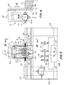
- Figs. 3 and 4 show an application of the invention to a machine tool or work center with a portal structure, rather than with a vertical upright, to support the toolhead.
- the machine indicated as a whole with 101, has a portal structure 103 comprising two vertical uprights 104, which support a crosspiece 107.
- Two guides 105 extend along the crosspiece 107 in a horizontal direction X, which also represents the first numerically controlled axis of translation.
- a carriage or slide 39 equipped with vertical guides 110 translates along the guides 105.
- a slide 111 carrying a toolhead, again indicated as a whole with 13, translates along the vertical guides 110 according to a vertical direction Z (which represents a numerically controlled axis of vertical translation).
- the same parts shown in the example of embodiment in Figs. 1 and 2 and indicated with the same reference numbers, not described again here, are mounted on the toolhead 13.
- a bed 143 extends below the portal structure 103, along which two carriages or slides 151 and 153 run respectively. Alternatively, a single carriage or slide may be provided.
- the bed 143 extends in a direction orthogonal to the plane in Fig.3, which coincides with the direction of a second numerically controlled axis of horizontal translation, indicated with Y.
- Respective means 155 and 157 are mounted on the slides or carriages 151 and 153 to support and clamp the workpieces to be machined, not shown. Also in this case the supporting means 155 and 157 can be adjusted in order to define surfaces to support and clamp workpieces of variable dimensions, as a function of the dimensional and morphological characteristics of said workpieces.
- the workpieces and the toolhead can move in relation to each other according to three numerically controlled axes of translation X, Y and Z, just as in the previous example.
- the use of two slides or carriages 151 and 153 allows the machine tool to machine in an oscillating cycle, that is to position and machine a workpiece or a series of workpieces by means of the slide 151, which is positioned under the toolhead 13, while the other slide or carriage 153 is transferred to a loading and unloading area, far from the area of operating of the toolhead 13.
- the numerically controlled movement along the three axes of horizontal and vertical translation X, Y, Z are the numerically controlled movements of oscillation or rotation around the numerically controlled axes of rotation B1, B2 and C which the toolhead 13 is provided with.
- each of the two chuck assemblies 21 and 31 with two or three chucks rather than four.
- the toolhead 13 may be taken to the position shown with the dashed line in Fig.3, to machine (with a chuck arranged with a horizontal axis) a side of a workpiece clamped on the means 155, without any chuck facing downward with its tool projecting beyond the part being machined.
- the toolhead 13 may also be designed differently to the illustration in Figs. 1 to 4.
- Fig.5 shows a toolhead, again indicated with 13, in which each chuck assembly has four chucks in a cross arrangement.
- Equivalent numbers indicate parts equivalent or corresponding to those of the toolheads 13 shown in the previous figures. While a toolhead with this arrangement may have a few additional difficulties concerning the risk of collision between tools and the workpiece being machined, it makes it possible to provide a larger number of tools on the machine.
- Figs. 6 and 7 show a different embodiment of the toolhead 13, which may be utilized alternatively to the previously illustrated embodiments.
- Equivalent numbers indicate parts equivalent or corresponding to those in the previous embodiments.
- the main difference between the embodiment in Figs. 6 and 7 and the previously described embodiments lies in the fact that the arms 17 and 19 are not fixedly mounted on the support 15, but may slide along guides 16 orthogonal to the axis of rotation C and to the main direction of the arms 17, 19.
- the movement along the guides 16 may be manual or motorized, obtained for example by means of a threaded bar and nut screw mechanism and an actuator, not shown.
- this configuration allows variation of the distance between the chuck assemblies 21 and 31, to adopt one or other of the reciprocal positions shown in Figs. 6 and 7 or any intermediate position.
- the movement of the arms 17 and 19 along the support 15 may also be controlled by two independent actuators.
- the arms 17 and 19 may also adopt positions that are not symmetrical with the axis of oscillation or rotation C.
- one of the two arms, 17 or 19, may be fixed in relation to the support 15 and the distance between the arms may be modified by translating only one of the arms in relation to the other.
- each chuck assembly 21, 31 comprises two coaxial chucks, indicated with 23 and 33 respectively.
- Figs. 9 and 10 show a double-rotating head of a type analogous to the one shown in Figs. 6 and 7, where each chuck assembly 21, 31 again has two coaxial chucks.
- Figs. 11 and 12 schematically show the advantage attained from the arrangement of two chuck assemblies each with two coaxial chucks, as is the case for the double-rotating head in Figs. 8 to 10.
- Figs. 11 and 12 only show the chucks and their respective tools, while the structure of the head is omitted to simplify the drawing.
- Fig. 11 shows the machining of a backrest S of a chair by means of a traditional toolhead equipped with four chucks in a cross arrangement, indicated with M1-M4, on which four tools U1-U4 are fitted.
- M1-M4 the toolhead equipped with four chucks in a cross arrangement
- FIG. 12 shows the same machining performed on a workpiece S with the same shape, by means of a toolhead of the type shown in Fig. 8 or of the type shown in Figs. 9 and 10. While the tool U4 coupled on one of the chucks 33 of the chuck assembly 31 is operating, the common axis of the two chucks 23 of the chuck assembly 21 may be rotated so that it is not positioned at 90° in relation to the axis of the chucks 33, so that the tool U1 does not collide with the workpiece being machined S.
- the angle ⁇ between the two axes A1, A2 of the chuck assemblies may vary during machining thanks to the independent numeric control on the two axes of rotation B1, B2.
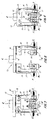
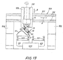
- Fig. 13 shows a portal machine tool or work center of the type shown in Fig. 3.
- Equivalent numbers indicated parts equivalent or corresponding to those in Fig. 3.
- the double-rotating toolhead is shown rotated by 90° around the axis C in relation to the position adopted in Fig. 3.
- it is equipped in this case with two assemblies, each with two chucks, that is of the type shown in Fig.8 or in Figs. 9 and 10.
- a body S1 of a chair clamped on a template SA in turn mounted on clamping means 155.
- the axes along which the chucks 23 and 33 of the chuck assemblies are aligned are inclined by an angle of less than 90°, which may be varied during machining of the workpiece, to prevent tools not being utilized from colliding with the workpiece or with the machine structure.
- Figs. 14A and 14B show a machine with portal structure analogous to the one in Fig.13.
- Fig. 14A it is equipped with a double-rotating toolhead with four tools in a cross arrangement
- Fig.14B it is provided with a double-rotating head of the type in Fig.8 or 9, 10.
- Fig.14A there is the risk of collision between the tool U4 (not operating) and the carriage 151, while the tools U1 and U3 are operating.
- the risk of collision is prevented, while having the same number of tools available.
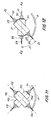
- Figs. 15A and 15B show how the same advantage can be attained with a structure of the toolhead in which the two chucks of each assembly are arranged in an L, with the axes at 90° rather than coaxial.
- a layout is shown in which the traditional configuration in Fig. 15A would make it impossible to perform machining except with the use of an angle drive fitted to the chuck.
- Fig.16 schematically shows a possible machining of this type.
- P1 and P2 indicate two identical workpieces and U1 and U2 two identical tools which simultaneously perform the same machining on the two workpieces.
- the two tools U1, U2 belong to two different chuck assemblies 21, 31 of the same toolhead.
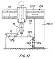
- Fig. 17 shows a machine tool with a half-portal or open bridge structure.
- the machine has an open L-shaped structure, indicated with 201 movable along guides 203 integral with a bed 205. Arranged on the bed are clamping means constituted in the example shown by so-called supporting blocks 209 for the workpieces P.
- the open structure 201 has a vertical upright 201 M and a horizontal crosspiece 201 T, equipped with guides 211 along which a slide 213 runs carrying the double-rotating head indicated with 13.
- the toolhead may be produced according to any one of the previous embodiments.
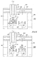
- Figs. 18 and 19 show a front view and a side view of a machine with portal structure with a double-rotating toolhead with assemblies each comprising two chucks with axes positioned at 90° according to an L-shaped arrangement.
- the toolhead is in different positions.
- the workpieces being machined P are carried by uprights 251, 253 carried by carriages or slides 151, 153.
- Workpieces are clamped by suction, as the blocks are associated with suction means, also called suction cups.
- the clamping system with beams and blocks of this type is per se known and described for example in WO-A-9523047.
- the two figures 18 and 19 show the versatility of the system equipped with the toolhead according to the invention, which makes it possible to prevent collisions between tools and the machine structure or workpieces being machined, even with uprights 251, 253 of moderate height, or with blocks 256, 258 of limited height (so as not to knock against the beams 255, 257).
- the height of the uprights it is sufficient for the height of the uprights to be at least half the diameter of the chucks.
- the two numerically controlled axes B1, B2 makes it possible to provide a sufficient number of chucks to perform the entire machining cycle and in any case a number of chucks and tools corresponding to at least to the number available on a traditional head with four chucks in a cross arrangement.
Priority Applications (1)
| Application Number | Priority Date | Filing Date | Title |
|---|---|---|---|
| EP03425117A EP1452269A1 (de) | 2003-02-25 | 2003-02-25 | Werkzeugkopf für Werkzeugmaschinen oder Bearbeitungszentren sowie Maschine mit einem solchen Werkzeugkopf |
Applications Claiming Priority (1)
| Application Number | Priority Date | Filing Date | Title |
|---|---|---|---|
| EP03425117A EP1452269A1 (de) | 2003-02-25 | 2003-02-25 | Werkzeugkopf für Werkzeugmaschinen oder Bearbeitungszentren sowie Maschine mit einem solchen Werkzeugkopf |
Publications (1)
| Publication Number | Publication Date |
|---|---|
| EP1452269A1 true EP1452269A1 (de) | 2004-09-01 |
Family
ID=32749045
Family Applications (1)
| Application Number | Title | Priority Date | Filing Date |
|---|---|---|---|
| EP03425117A Withdrawn EP1452269A1 (de) | 2003-02-25 | 2003-02-25 | Werkzeugkopf für Werkzeugmaschinen oder Bearbeitungszentren sowie Maschine mit einem solchen Werkzeugkopf |
Country Status (1)
| Country | Link |
|---|---|
| EP (1) | EP1452269A1 (de) |
Cited By (8)
| Publication number | Priority date | Publication date | Assignee | Title |
|---|---|---|---|---|
| WO2007077589A1 (en) | 2006-01-03 | 2007-07-12 | Lg Technologies S.R.L. | Drilling device |
| DE102006026186A1 (de) * | 2006-05-30 | 2007-12-06 | Index-Werke Gmbh & Co. Kg Hahn & Tessky | Werkzeugmaschine |
| WO2007144922A1 (en) * | 2006-06-16 | 2007-12-21 | Paolino Bacci S.R.L. | Machine tool or work centre for pieces made of wood and the like |
| EP2058071A1 (de) * | 2006-08-04 | 2009-05-13 | Citizen Holdings Co., Ltd. | Kombination aus bearbeitungsdrehbank und ihrem werkzeughalter |
| EP2500133A1 (de) | 2011-03-18 | 2012-09-19 | Paolino Bacci S.r.l. | Werkzeugkopf für Werkzeugmaschinen oder Werkbänke und Maschine mit diesem Kopf |
| EP3257629A1 (de) * | 2016-06-15 | 2017-12-20 | WENDT GmbH | Schleifmaschine |
| DE102020134737A1 (de) | 2020-12-22 | 2022-06-23 | Klaus-Dieter Klement Verwaltungs Gmbh | Bearbeitungsmaschine |
| CN114799914A (zh) * | 2022-05-10 | 2022-07-29 | 常德永盛液压机械有限公司 | 一种转盘式快速钻孔设备 |
Citations (12)
| Publication number | Priority date | Publication date | Assignee | Title |
|---|---|---|---|---|
| US3786539A (en) * | 1969-10-16 | 1974-01-22 | Index Werke Kg Hahn & Tessky | Multiple tool turret |
| DE3330653A1 (de) * | 1983-08-25 | 1985-03-21 | Manfred Dipl.-Ing. 7312 Kirchheim Kanal | Revolverdrehautomat bzw. nc-drehmaschine mit einem radial geteilten werkzeugrevolverkopf |
| JPH01316101A (ja) * | 1988-06-16 | 1989-12-21 | Okuma Mach Works Ltd | 旋盤の加工方法並びにそのためのタレツト刃物台 |
| DE9218976U1 (de) * | 1992-10-27 | 1996-07-11 | Heidelberger Druckmasch Ag | Werkzeugmaschine zur spanabhebenden Bearbeitung |
| EP0740978A1 (de) * | 1995-05-03 | 1996-11-06 | Bernhard Eisenbach | Bearbeitungsmaschine für stabförmige Werkstücke, insbesondere Hohlprofile |
| EP0744244A1 (de) * | 1995-05-24 | 1996-11-27 | Ditta Bacci Paolino Di Giuseppe Bacci Di Agostino Bacci | Werkzeugmaschine zum Bearbeiten von länglichen Elementen mit als Ausleger montierten Werkstückträger |
| DE19528404A1 (de) * | 1995-08-02 | 1997-02-06 | Spinner Werkzeugmaschinenfabri | Werkzeugmaschine und Verfahren zum gleichzeitigen Bearbeiten zweier Werkstücke |
| EP0873817A1 (de) * | 1998-03-31 | 1998-10-28 | Ditta Bacci Paolino Di Giuseppe Bacci Di Agostino Bacci | Werkzeugmaschine zum Bearbeiten von langen Werkstücken |
| EP1002620A1 (de) * | 1998-11-18 | 2000-05-24 | Ditta Bacci Paolino Di Giuseppe Bacci Di Agostino Bacci | Werkzeugmaschine mit Schwenktischen |
| EP1055485A2 (de) * | 1999-05-07 | 2000-11-29 | Bacci Paolino Di Giuseppe Bacci Di Agostino Bacci | Werkzeugmaschine zum Bearbeiten von länglichen symmetrischen Gegenständen sowie Bauteilen von Stühlen, Möbeln und anderen ähnlichen Gegenständen |
| DE19950073A1 (de) * | 1999-10-18 | 2001-04-26 | Ketterer Maschb Gmbh | Werkzeugbearbeitungsmaschine mit einem Schaltteller |
| WO2002036302A1 (en) * | 2000-10-31 | 2002-05-10 | Pade S.A.S. Di De Moliner Vinicio & C. | Tenoning machine |
-
2003
- 2003-02-25 EP EP03425117A patent/EP1452269A1/de not_active Withdrawn
Patent Citations (12)
| Publication number | Priority date | Publication date | Assignee | Title |
|---|---|---|---|---|
| US3786539A (en) * | 1969-10-16 | 1974-01-22 | Index Werke Kg Hahn & Tessky | Multiple tool turret |
| DE3330653A1 (de) * | 1983-08-25 | 1985-03-21 | Manfred Dipl.-Ing. 7312 Kirchheim Kanal | Revolverdrehautomat bzw. nc-drehmaschine mit einem radial geteilten werkzeugrevolverkopf |
| JPH01316101A (ja) * | 1988-06-16 | 1989-12-21 | Okuma Mach Works Ltd | 旋盤の加工方法並びにそのためのタレツト刃物台 |
| DE9218976U1 (de) * | 1992-10-27 | 1996-07-11 | Heidelberger Druckmasch Ag | Werkzeugmaschine zur spanabhebenden Bearbeitung |
| EP0740978A1 (de) * | 1995-05-03 | 1996-11-06 | Bernhard Eisenbach | Bearbeitungsmaschine für stabförmige Werkstücke, insbesondere Hohlprofile |
| EP0744244A1 (de) * | 1995-05-24 | 1996-11-27 | Ditta Bacci Paolino Di Giuseppe Bacci Di Agostino Bacci | Werkzeugmaschine zum Bearbeiten von länglichen Elementen mit als Ausleger montierten Werkstückträger |
| DE19528404A1 (de) * | 1995-08-02 | 1997-02-06 | Spinner Werkzeugmaschinenfabri | Werkzeugmaschine und Verfahren zum gleichzeitigen Bearbeiten zweier Werkstücke |
| EP0873817A1 (de) * | 1998-03-31 | 1998-10-28 | Ditta Bacci Paolino Di Giuseppe Bacci Di Agostino Bacci | Werkzeugmaschine zum Bearbeiten von langen Werkstücken |
| EP1002620A1 (de) * | 1998-11-18 | 2000-05-24 | Ditta Bacci Paolino Di Giuseppe Bacci Di Agostino Bacci | Werkzeugmaschine mit Schwenktischen |
| EP1055485A2 (de) * | 1999-05-07 | 2000-11-29 | Bacci Paolino Di Giuseppe Bacci Di Agostino Bacci | Werkzeugmaschine zum Bearbeiten von länglichen symmetrischen Gegenständen sowie Bauteilen von Stühlen, Möbeln und anderen ähnlichen Gegenständen |
| DE19950073A1 (de) * | 1999-10-18 | 2001-04-26 | Ketterer Maschb Gmbh | Werkzeugbearbeitungsmaschine mit einem Schaltteller |
| WO2002036302A1 (en) * | 2000-10-31 | 2002-05-10 | Pade S.A.S. Di De Moliner Vinicio & C. | Tenoning machine |
Non-Patent Citations (1)
| Title |
|---|
| PATENT ABSTRACTS OF JAPAN vol. 014, no. 119 (M - 0945) 6 March 1990 (1990-03-06) * |
Cited By (19)
| Publication number | Priority date | Publication date | Assignee | Title |
|---|---|---|---|---|
| WO2007077589A1 (en) | 2006-01-03 | 2007-07-12 | Lg Technologies S.R.L. | Drilling device |
| CN101370617B (zh) * | 2006-01-03 | 2011-06-08 | Lg技术有限公司 | 钻孔装置 |
| US7926155B2 (en) | 2006-05-30 | 2011-04-19 | Index-Werke Gmbh & Co. Kg Hahn & Tessky | Machine tool |
| DE102006026186A1 (de) * | 2006-05-30 | 2007-12-06 | Index-Werke Gmbh & Co. Kg Hahn & Tessky | Werkzeugmaschine |
| WO2007144922A1 (en) * | 2006-06-16 | 2007-12-21 | Paolino Bacci S.R.L. | Machine tool or work centre for pieces made of wood and the like |
| CN103223504A (zh) * | 2006-08-04 | 2013-07-31 | 西铁城控股株式会社 | 刀架和复合加工车床 |
| EP2058071A1 (de) * | 2006-08-04 | 2009-05-13 | Citizen Holdings Co., Ltd. | Kombination aus bearbeitungsdrehbank und ihrem werkzeughalter |
| EP2428295A1 (de) * | 2006-08-04 | 2012-03-14 | Citizen Holdings Co., Ltd. | Werkzeughalter |
| CN103223504B (zh) * | 2006-08-04 | 2015-09-02 | 西铁城控股株式会社 | 刀架和复合加工车床 |
| EP2058071A4 (de) * | 2006-08-04 | 2009-07-22 | Citizen Holdings Co Ltd | Kombination aus bearbeitungsdrehbank und ihrem werkzeughalter |
| US8297158B2 (en) | 2006-08-04 | 2012-10-30 | Citizen Holdings Co., Ltd. | Combined processing lathe and its tool post |
| CN101500738B (zh) * | 2006-08-04 | 2013-05-22 | 西铁城控股株式会社 | 复合加工车床及其刀架 |
| ITFI20110040A1 (it) * | 2011-03-18 | 2012-09-19 | Paolino Bacci Srl | "testa porta-utensili per macchine utensili o centri di lavoro, e macchina comprendente detta testa" |
| EP2500133A1 (de) | 2011-03-18 | 2012-09-19 | Paolino Bacci S.r.l. | Werkzeugkopf für Werkzeugmaschinen oder Werkbänke und Maschine mit diesem Kopf |
| EP3257629A1 (de) * | 2016-06-15 | 2017-12-20 | WENDT GmbH | Schleifmaschine |
| WO2017218318A1 (en) * | 2016-06-15 | 2017-12-21 | 3M Innovative Properties Company | Grinding machine |
| DE102020134737A1 (de) | 2020-12-22 | 2022-06-23 | Klaus-Dieter Klement Verwaltungs Gmbh | Bearbeitungsmaschine |
| EP4019189A1 (de) * | 2020-12-22 | 2022-06-29 | Klaus-Dieter Klement Verwaltungs GmbH | Bearbeitungsmaschine |
| CN114799914A (zh) * | 2022-05-10 | 2022-07-29 | 常德永盛液压机械有限公司 | 一种转盘式快速钻孔设备 |
Similar Documents
| Publication | Publication Date | Title |
|---|---|---|
| KR100241837B1 (ko) | 다수의 스핀들을 구비한 공작 기계 | |
| JP4763938B2 (ja) | 工作機械 | |
| CN1064875C (zh) | 带有水平主轴的机床 | |
| US7493681B2 (en) | Machine tool | |
| JP2008540145A (ja) | 別々のキャリッジに2つのクランプ点を備えた工作機械 | |
| US11167354B2 (en) | Machine tool, in particular lathe | |
| US20080254959A1 (en) | Universal head and machine tool with universal head | |
| US6651535B2 (en) | Lathe | |
| CN109759924B (zh) | 双龙门单横梁移动式组合加工机床 | |
| US7124666B2 (en) | Multiple spindle machine tool | |
| KR101689404B1 (ko) | 복합선반 및 워크의 가공방법 | |
| EP1452269A1 (de) | Werkzeugkopf für Werkzeugmaschinen oder Bearbeitungszentren sowie Maschine mit einem solchen Werkzeugkopf | |
| US20120076598A1 (en) | Milling machine for producing toothed wheels | |
| JP2003225806A (ja) | 複合nc旋盤のフレーム構造 | |
| US4798504A (en) | Workpiece machining apparatus and method | |
| US6484611B1 (en) | Lathe | |
| EP3858542B1 (de) | Numerisch gesteuerte mehrspindeldrehmaschine | |
| EP3581327A1 (de) | Werkzeugmaschine | |
| US7318693B2 (en) | Device for machining workpieces and machine arrangement therefor | |
| CN112454074A (zh) | 一种小型工件加工磨床 | |
| EP4043146A1 (de) | Numerisch gesteuerte mehrspindeldrehmaschine mit auf einer horizontalen ebene liegenden drehachsen | |
| JPS5929363B2 (ja) | 旋盤 | |
| CN219747180U (zh) | 一种卧式加工机床 | |
| EP3871834A1 (de) | Werkzeugmaschine, insbesondere drehmaschine mit hilfsspindel | |
| CN219725511U (zh) | 一种龙门加工中心产品偏移检测用激光定位装置 |
Legal Events
| Date | Code | Title | Description |
|---|---|---|---|
| PUAI | Public reference made under article 153(3) epc to a published international application that has entered the european phase |
Free format text: ORIGINAL CODE: 0009012 |
|
| AK | Designated contracting states |
Kind code of ref document: A1 Designated state(s): AT BE BG CH CY CZ DE DK EE ES FI FR GB GR HU IE IT LI LU MC NL PT SE SI SK TR |
|
| AX | Request for extension of the european patent |
Extension state: AL LT LV MK RO |
|
| AKX | Designation fees paid | ||
| REG | Reference to a national code |
Ref country code: DE Ref legal event code: 8566 |
|
| STAA | Information on the status of an ep patent application or granted ep patent |
Free format text: STATUS: THE APPLICATION IS DEEMED TO BE WITHDRAWN |
|
| 18D | Application deemed to be withdrawn |
Effective date: 20050302 |