EP1452088A1 - Futtererntemaschine - Google Patents
Futtererntemaschine Download PDFInfo
- Publication number
- EP1452088A1 EP1452088A1 EP04002624A EP04002624A EP1452088A1 EP 1452088 A1 EP1452088 A1 EP 1452088A1 EP 04002624 A EP04002624 A EP 04002624A EP 04002624 A EP04002624 A EP 04002624A EP 1452088 A1 EP1452088 A1 EP 1452088A1
- Authority
- EP
- European Patent Office
- Prior art keywords
- frame
- movement
- machine according
- pivot axis
- front part
- Prior art date
- Legal status (The legal status is an assumption and is not a legal conclusion. Google has not performed a legal analysis and makes no representation as to the accuracy of the status listed.)
- Granted
Links
- 239000004459 forage Substances 0.000 title claims description 18
- 230000033001 locomotion Effects 0.000 claims abstract description 59
- 238000012423 maintenance Methods 0.000 claims abstract description 17
- 238000003306 harvesting Methods 0.000 claims description 8
- 230000007704 transition Effects 0.000 claims description 4
- 230000008901 benefit Effects 0.000 description 5
- 241001124569 Lycaenidae Species 0.000 description 3
- 238000004091 panning Methods 0.000 description 3
- 238000010276 construction Methods 0.000 description 2
- 238000011161 development Methods 0.000 description 2
- 230000018109 developmental process Effects 0.000 description 2
- 230000002349 favourable effect Effects 0.000 description 2
- 230000005484 gravity Effects 0.000 description 2
- 240000008042 Zea mays Species 0.000 description 1
- 235000005824 Zea mays ssp. parviglumis Nutrition 0.000 description 1
- 235000002017 Zea mays subsp mays Nutrition 0.000 description 1
- 235000005822 corn Nutrition 0.000 description 1
- 230000000694 effects Effects 0.000 description 1
- 238000007689 inspection Methods 0.000 description 1
- 239000003973 paint Substances 0.000 description 1
- 230000035515 penetration Effects 0.000 description 1
- 230000003068 static effect Effects 0.000 description 1
- 238000003860 storage Methods 0.000 description 1
Images





Classifications
-
- A—HUMAN NECESSITIES
- A01—AGRICULTURE; FORESTRY; ANIMAL HUSBANDRY; HUNTING; TRAPPING; FISHING
- A01F—PROCESSING OF HARVESTED PRODUCE; HAY OR STRAW PRESSES; DEVICES FOR STORING AGRICULTURAL OR HORTICULTURAL PRODUCE
- A01F29/00—Cutting apparatus specially adapted for cutting hay, straw or the like
- A01F29/09—Details
Definitions
- the invention relates to a forage harvesting machine with a Feed and cutting head device according to the preamble of Claim 1.
- the use of forage harvesters or so-called Forage harvesters is used in agricultural forage advertising in use for a long time.
- the feed like corn or green fodder is here through a header cut and a feed and cutting device for Shredding fed.
- the feeder consists of usually two or more feed rollers that the Capture the crop and transport it to the cutter.
- the cutting device usually consists of a Knife drum against a fixed shear bar rotates.
- Such a harvesting machine is used, for example, in the Document EP 300 299 described.
- the move-in Cutting device in a two-part frame housed the cutter in the static rear frame part (related to the direction of travel of the Machine) and the feed device in the front of the frame is housed.
- the front frame part For maintenance purposes to the one in the back
- the front frame part For maintenance purposes to the one in the back
- the front frame part For maintenance purposes to the one in the back
- To get part of the machine areas housed is the front frame part by a substantially vertical Swivel axis rotatably mounted. The front part of the frame swings away to the side, so that the rear part is fully accessible.
- DE 32 36 984 A1 relates to a forage harvester, at the non-separable cutting box for maintenance purposes fully forward and down to the front wheels its operating position is pulled out.
- the Cutting box on angular elements movable over rollers.
- a harvesting machine is known from DE 100 21 658 A1, being a front gear and a feed gear behind the front axle of the harvester in a common Gear housing is arranged.
- a disadvantage of these devices is the fact that the Feed and cutting device or its frame comparatively far in front so that the front frame part can be swiveled completely to the side can, without hitting the front wheels of the forage harvester bump.
- the header is forcibly in front of the Feed and cutting device must be arranged this results in an unfavorable load distribution or Center of gravity of the entire machine.
- the object of the invention is a Propose forage harvesters that get you as far as possible related to the forward drive backwards Main focus of the feed and cutting device at at the same time unrestricted access to maintenance-prone Machine parts guaranteed.
- one according to the invention is distinguished Feeding machine according to the preamble of claim 1 thereby from that the transition between the closed Operating position and the open maintenance position a forward movement and a sideways movement of the Frame front part is feasible, at least that Front part of the frame around a pivotable axis of rotation or pivoting axis is rotatable. This is the weight of this Machine parts moved backwards in the operating position, so that the desired more favorable load distribution during of operation results.
- the header be structurally redesigned in such a way that it benefits the load distribution is also shifted backwards.
- the Front structure i.e. especially the header if required be made larger and thus heavier.
- the Front wheels can be made larger.
- the transition between the operating position according to the invention between the front wheels in the front wheels or the front wheel is in the maintenance position achieved in that both for the frame front part Forward as well as sideways movement is provided.
- a vertical movement of the frame front part is also provided.
- Such a vertical movement which is preferred as Downward movement is formed, which shortens the Forward movement that is required to achieve that To be able to arrange the front part of the frame in front of the wheel. ever the greater the distance from the wheel center plane, the smaller the forward movement can fail.
- an arrangement of the frame according to the invention or the feed and cutting device realizable that the front part of the frame e.g. by a Plain bearing, slidable or extendable and is then swiveled to the side.
- the pivot axis can, for example arranged horizontally to stand in the above the advantages mentioned in the technical document maintain.
- the forward movement and the Sideways movement take place simultaneously superimposed.
- This is, for example, in a particularly simple one Embodiment possible when a pivoting movement around a single swivel axis inclined forward is provided.
- This movement may be enough Front part in a forward, downward and sideways movement in front of the front wheel.
- the shape of the Front wheel exploited, the maximum forward movement the moving part of the feeder and cutter everything required at the level of the wheel axle.
- the forward, Downward movement using an inclined swivel axis it is thus possible to slant the front part of the frame inclined at the front to move in front of the front wheel.
- This execution has the advantage that only a single pivot axis must be provided.
- the Swivel axis can also be inclined laterally to the Support sideways movement.
- a successive movement is provided.
- Sequence of a shift with a swivel movement can also be a sequence of two Panning movements in a special embodiment be provided. So an initially vertical one First swivel axis together with the movable front part of the Frame of the cutting and feeding device by one in Main horizontal swivel axis inclined forward to be subsequently pivoted around the in this position obliquely forward inclined pivot axis to release the rear part of the frame in which the swiveling frame part downwards in front of the front wheel is pivoted.
- Such an embodiment offers a constructive one Alternative to a fixed slant Swivel axis and also offers the advantage of a forward inclined intermediate position, in the certain maintenance and / or Inspection activities are already undertaken can without the fully open maintenance position take. In particular, this intermediate position is possible without completely removing the header.
- the successive sequence of the two Panning movements are advantageous in that closed operating position of the frame front part Lateral overlap with the rear frame part possible is that by the forward, downward, panning motion around canceled a substantially horizontal pivot axis can be. This way this overlap can be eliminated before the lateral swiveling movement starts, so that the corresponding frame parts producing the overlap do not interfere with each other when moving sideways.
- a corresponding control unit for example with an or provided several hydraulic cylinders.
- a Drive device is advantageous because these machine parts can have considerable weight.
- the frame front part is locked with the rear frame part provided to during the Operational relief of the swivel axis or appropriate storage for the movement of the Front part of the frame and safe positioning of the two To achieve frame parts.
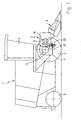
- Figure 1 shows the forage harvester 1, which as self-propelled machine with front wheels 2 and rear wheels 3 is trained. Such machines are usually over the rear wheels 3 steerable.
- the front wheel 2 is located below the driver's cab 4. Between the front wheels 2 is the retraction and Cutting device 5 mounted behind a header 6.
- the feed and cutting device is with one two-piece frame equipped which is a rear Frame part 7 and a frame front part 8 comprises. in the rear part 7 are a knife drum 9, in Frame front part 8 four feed rollers assigned in pairs 10 indicated. In this operating position according to FIG. 1 the frame front part 8 is at least partially between the front wheels 2.
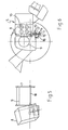
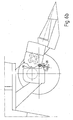
- the frame front part 8 has a pivot axis 11 (cf. Figure 6) pivotally mounted in a bearing eye 12.
- the eye 12 is provided on the outside with a spherical contour and in a bearing plate 13, which has a corresponding inner contour has rotatably mounted. Due to the spherical shape of the Bearing eye 12 is basically the pivot axis 11 in all Swiveling directions.
- the possible swiveling movements are by a fork 14 restricted within which the pivot axis 11 with her outer end 15 is guided.
- the base 16 of the fork 14 forms at the same time a stop for the pivot axis 11.
- the second fully opened maintenance position according to the figure 3 is only due to the previous downward movement and the like manufactured inclination of the pivot axis 11 and previous forward movement so that the lateral Overlaps 19 of the feed no longer the drum paint over, reachable.
- FIGS. 6a and 6b it can be seen that in the closed operating position a side projection 19 of the Frame front part 8, the rear frame part 7 on both sides grips so that there is an overlap.
- this overlap is resolved by the side protrusions 19 come to rest in front of the rear frame part 7.
- On this allows the subsequent sideways / downward pivoting take place without the side projection 19 with the rear frame part 7 or the housed therein Machine components collided.
- the construction according to the invention makes it possible to Feed and cutting device 5 further back into the Shift area between the front wheels 2, whereby basically also the header 6 further back can be relocated. This results in a total of one much cheaper load distribution.
- This cheaper Load balancing can be used, for example, for better Driving stability or for larger and heavier machine parts, can be used in particular in the area of the header 6.
Landscapes
- Life Sciences & Earth Sciences (AREA)
- Environmental Sciences (AREA)
- Harvester Elements (AREA)
- Threshing Machine Elements (AREA)
Abstract
Description
- Figur 1
- einen schematischen Längsschnitt durch eine erfindungsgemäße Futtererntemaschine,
- Figur 2
- eine Darstellung der Futtererntemaschine gemäß Figur 1 in einer ersten Wartungsstellung,
- Figur 3
- einen schematischen Querschnitt durch eine Futtererntemaschine gemäß Figur 1,
- Figur 4
- eine schematische Frontansicht einer erfindungsgemäßen Futtererntemaschine,
- Figur 5
- eine Ausschnittsvergrößerung der Einzugs- und Schneideinrichtung in der Frontansicht,
- Figur 6
- eine Ausschnittvergrößerung mit Einzugs- und Schneideinrichtung gemäß Figur 2,
- Figur 6a
- eine Vergrößerung der Darstellung gemäß Figur 6 in geschlossener Betriebsstellung,
- Figur 6b
- eine Figur 6a entsprechende Darstellung bei jedoch in der nach vorn geschwenkten Zwischenstellung des Rahmenvorderteils,
- Figur 7a
- eine Vergrößerung der Lagerkonstruktion des Rahmenvorderteils in geschlossener Betriebsstellung gemäß Figur 6a,
- Figur 7b
- eine Figur 7a entsprechende Darstellung in nach vorn geschwenkter Zwischenstellung des Rahmenvorderteils entsprechend Figur 6b,
- Figur 8
- einen Schnitt durch Schnittlinie VIII in Figur 7a.
- 1
- Futtererntemaschine
- 2
- Vorderrad
- 3
- Hinterrad
- 4
- Fahrkabine
- 5
- Einzugs- und Schneideinrichtung
- 6
- Erntevorsatz
- 7
- Rückwärtiges Rahmenteil
- 8
- Rahmenvorderteil
- 9
- Messertrommel
- 10
- Einzugswalze
- 11
- Schwenkachse
- 12
- Lagerauge
- 13
- Lagerplatte
- 14
- Gabel
- 15
- Ende
- 16
- Basis
- 17
- Sicht- und Durchgriffsspalt
- 18
- Gegenschneide
- 19
- Seitenvorsprung
- 20
- Horizontale Schwenkachse
- 21
- Führungsspalt
Claims (14)
- Futtererntemaschine (1) mit einer Einzugs- und Schneidkopfeinrichtung (5), die einen Rahmen (7, 8) umfasst, der einen rückwärtigen Rahmenteil (7) und ein Rahmenvorderteil (8) aufweist, wobei wenigstens ein Teil der Einzugs- und Schneideinrichtung (5) im Rahmenvorderteil (8) und wenigstens ein Teil der Einzugs- und Schneidvorrichtung (5) im rückwärtigen Rahmenteil (7) angeordnet sind und wenigstens das Rahmenvorderteil (8) zwischen einer geschlossenen Betriebsstellung und einer geöffneten Wartungsstellung, in der der rückwärtige Rahmenteil (7) zur Wartung zugänglich ist, hin und her bewegbar ausgebildet ist, wobei das Rahmenvorderteil (8) in Betriebsstellung, quer zur Fahrtrichtung gesehen, in der Projektion der Vorderräder (2), wenigstens teilweise zwischen diesen und in der geöffneten Wartungsstellung wenigstens teilweise vor einem der Vorderräder (2) angeordnet ist, dadurch gekennzeichnet, dass der Übergang zwischen der geschlossenen Betriebsstellung und der geöffneten Wartungsstellung durch eine vorwärtsbewegung und eine Seitwärtsbewegung des Rahmenvorderteils (8) durchführbar ist, wobei wenigstens das Rahmenvorderteil um eine schwenkbare Drehachse (11, 20) drehbar ist.
- Maschine nach Anspruch 1, dadurch gekennzeichnet, dass eine Vertikalbewegung des Rahmenteils (8) vorgesehen ist.
- Maschine nach Anspruch 1 oder 2, dadurch gekennzeichnet, dass die Seitwärtsbewegung als Drehbewegung um die Drehachse (11) vorgesehen ist.
- Maschine nach einem der vorgenannten Ansprüche, dadurch gekennzeichnet, dass die vorwärtsbewegung als Schwenkbewegung um eine Schwenkachse (20) vorgesehen ist.
- Maschine nach einem der vorgenannten Ansprüche, dadurch gekennzeichnet, dass die Seitwärtsbewegung und die vorwärtsbewegung gleichzeitig überlagert sind.
- Maschine nach einem der vorgenannten Ansprüche, dadurch gekennzeichnet, dass die vorwärtsbewegung und die Seitwärtsbewegung nacheinander folgend vorgesehen sind.
- Maschine nach einem der vorgenannten Ansprüche, dadurch gekennzeichnet, dass eine schräg nach vorne geneigte Schwenkachse (11) für die Seitwärts- und/oder Vorwärtsbewegung und/oder Vertikalbewegung des Rahmenvorderteils (8) vorgesehen ist.
- Maschine nach einem der vorgenannten Ansprüche, dadurch gekennzeichnet, dass eine seitwärts geneigte Schwenkachse (11) für die Seitwärts- und/oder Vorwärtsbewegung und/oder Vertikalbewegung vorgesehen ist.
- Maschine nach einem der vorgenannten Ansprüche, dadurch gekennzeichnet, dass eine im Wesentlichen horizontale Schwenkachse für die Vorwärtsbewegung vorgesehen ist.
- Maschine nach einem der vorgenannten Ansprüche, dadurch gekennzeichnet, dass eine um eine horizontale Schwenkachse nach vorn schwenkbare Schwenkachse (11) vorgesehen ist.
- Maschine nach einem der vorgenannten Ansprüche, dadurch gekennzeichnet, dass ein Linearführung für das Rahmenvorderteil nach vorne vorgesehen ist.
- Maschine nach einem der vorgenannten Ansprüche, dadurch gekennzeichnet, dass das Rahmenvorderteil zusammen mit einer Schwenkachse nach vorn verschiebbar ausgebildet ist.
- Maschine nach einem der vorgenannten Ansprüche, dadurch gekennzeichnet, dass ein Antrieb für die Durchführung der vorwärts- und/oder Seitwärtsbewegung vorgesehen ist.
- Maschine nach einem der vorgenannten Ansprüche, dadurch gekennzeichnet, dass eine Verriegelung der Betriebs- und/oder Wartungsstellung vorgesehen ist.
Applications Claiming Priority (2)
| Application Number | Priority Date | Filing Date | Title |
|---|---|---|---|
| DE2003107836 DE10307836B4 (de) | 2003-02-25 | 2003-02-25 | Futtererntemaschine |
| DE10307836 | 2003-02-25 |
Publications (2)
| Publication Number | Publication Date |
|---|---|
| EP1452088A1 true EP1452088A1 (de) | 2004-09-01 |
| EP1452088B1 EP1452088B1 (de) | 2005-11-09 |
Family
ID=32748034
Family Applications (1)
| Application Number | Title | Priority Date | Filing Date |
|---|---|---|---|
| EP20040002624 Expired - Lifetime EP1452088B1 (de) | 2003-02-25 | 2004-02-06 | Futtererntemaschine |
Country Status (2)
| Country | Link |
|---|---|
| EP (1) | EP1452088B1 (de) |
| DE (2) | DE10307836B4 (de) |
Cited By (2)
| Publication number | Priority date | Publication date | Assignee | Title |
|---|---|---|---|---|
| EP2489254A1 (de) | 2011-02-18 | 2012-08-22 | CLAAS Saulgau GmbH | Einzugsvorrichtung für einen Feldhäcksler |
| EP3090623A1 (de) * | 2015-05-04 | 2016-11-09 | CLAAS Selbstfahrende Erntemaschinen GmbH | Selbstfahrender feldhäcksler |
Families Citing this family (1)
| Publication number | Priority date | Publication date | Assignee | Title |
|---|---|---|---|---|
| DE102012220339B4 (de) * | 2012-11-08 | 2021-06-17 | Deere & Company | Einzugs- und Messertrommelzusammenbau für einen Feldhäcksler |
Citations (4)
| Publication number | Priority date | Publication date | Assignee | Title |
|---|---|---|---|---|
| DE3236984A1 (de) | 1981-10-09 | 1983-04-28 | Hesston Corp., 67062 Hesston, Kan. | Erntemaschine mit herausziehbarem schneidkasten |
| EP0300299A1 (de) | 1987-07-20 | 1989-01-25 | Deere & Company | Einzugswalzen und Schneidkopf-Einrichtung |
| DE10021658A1 (de) | 2000-05-04 | 2001-11-15 | Krone Bernhard Gmbh Maschf | Erntemaschine, insbesondere selbstfahrender Feldhäcksler |
| DE10021661A1 (de) | 2000-05-04 | 2001-11-15 | Krone Bernhard Gmbh Maschf | Erntemaschine, insbesondere selbstfahrender Feldhäcksler |
-
2003
- 2003-02-25 DE DE2003107836 patent/DE10307836B4/de not_active Expired - Fee Related
-
2004
- 2004-02-06 DE DE200450000127 patent/DE502004000127D1/de not_active Expired - Lifetime
- 2004-02-06 EP EP20040002624 patent/EP1452088B1/de not_active Expired - Lifetime
Patent Citations (4)
| Publication number | Priority date | Publication date | Assignee | Title |
|---|---|---|---|---|
| DE3236984A1 (de) | 1981-10-09 | 1983-04-28 | Hesston Corp., 67062 Hesston, Kan. | Erntemaschine mit herausziehbarem schneidkasten |
| EP0300299A1 (de) | 1987-07-20 | 1989-01-25 | Deere & Company | Einzugswalzen und Schneidkopf-Einrichtung |
| DE10021658A1 (de) | 2000-05-04 | 2001-11-15 | Krone Bernhard Gmbh Maschf | Erntemaschine, insbesondere selbstfahrender Feldhäcksler |
| DE10021661A1 (de) | 2000-05-04 | 2001-11-15 | Krone Bernhard Gmbh Maschf | Erntemaschine, insbesondere selbstfahrender Feldhäcksler |
Cited By (3)
| Publication number | Priority date | Publication date | Assignee | Title |
|---|---|---|---|---|
| EP2489254A1 (de) | 2011-02-18 | 2012-08-22 | CLAAS Saulgau GmbH | Einzugsvorrichtung für einen Feldhäcksler |
| DE102011011658A1 (de) | 2011-02-18 | 2012-08-23 | Claas Saulgau Gmbh | Einzugsvorrichtung für einen Feldhäcksler |
| EP3090623A1 (de) * | 2015-05-04 | 2016-11-09 | CLAAS Selbstfahrende Erntemaschinen GmbH | Selbstfahrender feldhäcksler |
Also Published As
| Publication number | Publication date |
|---|---|
| DE10307836A1 (de) | 2004-09-09 |
| DE10307836B4 (de) | 2005-02-03 |
| DE502004000127D1 (de) | 2005-12-15 |
| EP1452088B1 (de) | 2005-11-09 |
Similar Documents
| Publication | Publication Date | Title |
|---|---|---|
| EP1393613B1 (de) | Vorrichtung zur Steuerung einer Überladeeinrichtung | |
| EP1464214B1 (de) | Erntemaschine zum Ernten von stängelartigem Erntegut wie Mais oder dergleichen | |
| EP0992187B1 (de) | Maschine zum Mähen von Mais und dgl. stengelartigem Erntegut | |
| EP2067397B1 (de) | Erntevorsatz für landwirtschaftliche Erntemaschinen zum Aufnehmen und Weiterfördern von Halmfrüchten | |
| EP2316259B1 (de) | Vorrichtung zum Halten eines die relative Position zu einem Erntebestand berührungslosen Sensors, insbesondere einer Kamera, an einer Erntemaschine | |
| EP1179292A1 (de) | Verfahren und Vorrichtung zum Schwenken der Abteiler von mehrteiligen landwirtschaftlichen Erntemaschinen | |
| DE3326297A1 (de) | Fahrzeug mit schwingungsbegrenzung | |
| EP0523578A2 (de) | Vierradlenkung für ein Fahrzeug | |
| EP3028557B1 (de) | Mäheinrichtung und verfahren zum betreiben einer mäheinrichtung | |
| DE60205226T2 (de) | Buschmäherfahrzeug | |
| DE10321683B4 (de) | Pfosten-Freimäher und Verfahren zum Einsatz des Freimähers | |
| EP2591653B2 (de) | Heuwerbungsmaschine | |
| EP4101275B1 (de) | Anbaugerät zur feldbearbeitung | |
| EP3788864A1 (de) | Aufnahmevorrichtung für eine landwirtschaftliche arbeitsmaschine, landwirtschaftliche arbeitsmaschine und arbeitszug mit einer solchen landwirtschaftlichen arbeitsmaschine | |
| DE68921495T2 (de) | Landwirtschaftsrolle. | |
| EP1894462B1 (de) | Landwirtschaftliches Trägerfahrzeug | |
| CH719870A2 (de) | Mähvorrichtung für ein Trägerfahrzeug. | |
| EP1452088B1 (de) | Futtererntemaschine | |
| DE2058255A1 (de) | Mit Abweisern am Schneidwerktisch versehener Maehdrescher | |
| DE102019005662A1 (de) | Auswurfkrümmer für einen Feldhäcksler | |
| DE60113599T2 (de) | Mähbrett für Erntemaschinen | |
| EP1305995B1 (de) | Schwenkvorrichtung für ein mehrteiliges Erntevorsatzgerät | |
| EP3132673A1 (de) | Hüllmaterialmagazin und erntebergungsgerät | |
| EP1588601A1 (de) | Erntemaschine mit einer Austrageinrichtung | |
| EP4197308B1 (de) | Häckselausrüstung sowie arbeitszug mit häckselausrüstung |
Legal Events
| Date | Code | Title | Description |
|---|---|---|---|
| PUAI | Public reference made under article 153(3) epc to a published international application that has entered the european phase |
Free format text: ORIGINAL CODE: 0009012 |
|
| AK | Designated contracting states |
Kind code of ref document: A1 Designated state(s): AT BE BG CH CY CZ DE DK EE ES FI FR GB GR HU IE IT LI LU MC NL PT RO SE SI SK TR |
|
| AX | Request for extension of the european patent |
Extension state: AL LT LV MK |
|
| 17P | Request for examination filed |
Effective date: 20041022 |
|
| AKX | Designation fees paid |
Designated state(s): BE DE |
|
| GRAP | Despatch of communication of intention to grant a patent |
Free format text: ORIGINAL CODE: EPIDOSNIGR1 |
|
| GRAS | Grant fee paid |
Free format text: ORIGINAL CODE: EPIDOSNIGR3 |
|
| GRAA | (expected) grant |
Free format text: ORIGINAL CODE: 0009210 |
|
| AK | Designated contracting states |
Kind code of ref document: B1 Designated state(s): BE DE |
|
| REF | Corresponds to: |
Ref document number: 502004000127 Country of ref document: DE Date of ref document: 20051215 Kind code of ref document: P |
|
| PG25 | Lapsed in a contracting state [announced via postgrant information from national office to epo] |
Ref country code: BE Free format text: LAPSE BECAUSE OF NON-PAYMENT OF DUE FEES Effective date: 20060228 |
|
| PLBE | No opposition filed within time limit |
Free format text: ORIGINAL CODE: 0009261 |
|
| STAA | Information on the status of an ep patent application or granted ep patent |
Free format text: STATUS: NO OPPOSITION FILED WITHIN TIME LIMIT |
|
| 26N | No opposition filed |
Effective date: 20060810 |
|
| BERE | Be: lapsed |
Owner name: CLAAS SAULGAU G.M.B.H. Effective date: 20060228 |
|
| PGFP | Annual fee paid to national office [announced via postgrant information from national office to epo] |
Ref country code: DE Payment date: 20220525 Year of fee payment: 20 |
|
| P01 | Opt-out of the competence of the unified patent court (upc) registered |
Effective date: 20230511 |
|
| REG | Reference to a national code |
Ref country code: DE Ref legal event code: R071 Ref document number: 502004000127 Country of ref document: DE |