EP1451592B1 - Angular velocity sensor - Google Patents
Angular velocity sensor Download PDFInfo
- Publication number
- EP1451592B1 EP1451592B1 EP02783320A EP02783320A EP1451592B1 EP 1451592 B1 EP1451592 B1 EP 1451592B1 EP 02783320 A EP02783320 A EP 02783320A EP 02783320 A EP02783320 A EP 02783320A EP 1451592 B1 EP1451592 B1 EP 1451592B1
- Authority
- EP
- European Patent Office
- Prior art keywords
- rotor
- event
- events
- revolution
- determining
- Prior art date
- Legal status (The legal status is an assumption and is not a legal conclusion. Google has not performed a legal analysis and makes no representation as to the accuracy of the status listed.)
- Expired - Lifetime
Links
Images

Classifications
-
- G—PHYSICS
- G01—MEASURING; TESTING
- G01D—MEASURING NOT SPECIALLY ADAPTED FOR A SPECIFIC VARIABLE; ARRANGEMENTS FOR MEASURING TWO OR MORE VARIABLES NOT COVERED IN A SINGLE OTHER SUBCLASS; TARIFF METERING APPARATUS; MEASURING OR TESTING NOT OTHERWISE PROVIDED FOR
- G01D18/00—Testing or calibrating apparatus or arrangements provided for in groups G01D1/00 - G01D15/00
- G01D18/001—Calibrating encoders
-
- G—PHYSICS
- G01—MEASURING; TESTING
- G01D—MEASURING NOT SPECIALLY ADAPTED FOR A SPECIFIC VARIABLE; ARRANGEMENTS FOR MEASURING TWO OR MORE VARIABLES NOT COVERED IN A SINGLE OTHER SUBCLASS; TARIFF METERING APPARATUS; MEASURING OR TESTING NOT OTHERWISE PROVIDED FOR
- G01D5/00—Mechanical means for transferring the output of a sensing member; Means for converting the output of a sensing member to another variable where the form or nature of the sensing member does not constrain the means for converting; Transducers not specially adapted for a specific variable
- G01D5/12—Mechanical means for transferring the output of a sensing member; Means for converting the output of a sensing member to another variable where the form or nature of the sensing member does not constrain the means for converting; Transducers not specially adapted for a specific variable using electric or magnetic means
- G01D5/244—Mechanical means for transferring the output of a sensing member; Means for converting the output of a sensing member to another variable where the form or nature of the sensing member does not constrain the means for converting; Transducers not specially adapted for a specific variable using electric or magnetic means influencing characteristics of pulses or pulse trains; generating pulses or pulse trains
- G01D5/24471—Error correction
- G01D5/2449—Error correction using hard-stored calibration data
-
- G—PHYSICS
- G01—MEASURING; TESTING
- G01P—MEASURING LINEAR OR ANGULAR SPEED, ACCELERATION, DECELERATION, OR SHOCK; INDICATING PRESENCE, ABSENCE, OR DIRECTION, OF MOVEMENT
- G01P3/00—Measuring linear or angular speed; Measuring differences of linear or angular speeds
- G01P3/42—Devices characterised by the use of electric or magnetic means
- G01P3/44—Devices characterised by the use of electric or magnetic means for measuring angular speed
-
- G—PHYSICS
- G01—MEASURING; TESTING
- G01D—MEASURING NOT SPECIALLY ADAPTED FOR A SPECIFIC VARIABLE; ARRANGEMENTS FOR MEASURING TWO OR MORE VARIABLES NOT COVERED IN A SINGLE OTHER SUBCLASS; TARIFF METERING APPARATUS; MEASURING OR TESTING NOT OTHERWISE PROVIDED FOR
- G01D18/00—Testing or calibrating apparatus or arrangements provided for in groups G01D1/00 - G01D15/00
- G01D18/008—Testing or calibrating apparatus or arrangements provided for in groups G01D1/00 - G01D15/00 with calibration coefficients stored in memory
-
- G—PHYSICS
- G01—MEASURING; TESTING
- G01P—MEASURING LINEAR OR ANGULAR SPEED, ACCELERATION, DECELERATION, OR SHOCK; INDICATING PRESENCE, ABSENCE, OR DIRECTION, OF MOVEMENT
- G01P21/00—Testing or calibrating of apparatus or devices covered by the preceding groups
- G01P21/02—Testing or calibrating of apparatus or devices covered by the preceding groups of speedometers
-
- G—PHYSICS
- G01—MEASURING; TESTING
- G01P—MEASURING LINEAR OR ANGULAR SPEED, ACCELERATION, DECELERATION, OR SHOCK; INDICATING PRESENCE, ABSENCE, OR DIRECTION, OF MOVEMENT
- G01P3/00—Measuring linear or angular speed; Measuring differences of linear or angular speeds
- G01P3/42—Devices characterised by the use of electric or magnetic means
- G01P3/44—Devices characterised by the use of electric or magnetic means for measuring angular speed
- G01P3/48—Devices characterised by the use of electric or magnetic means for measuring angular speed by measuring frequency of generated current or voltage
- G01P3/481—Devices characterised by the use of electric or magnetic means for measuring angular speed by measuring frequency of generated current or voltage of pulse signals
- G01P3/487—Devices characterised by the use of electric or magnetic means for measuring angular speed by measuring frequency of generated current or voltage of pulse signals delivered by rotating magnets
-
- G—PHYSICS
- G01—MEASURING; TESTING
- G01P—MEASURING LINEAR OR ANGULAR SPEED, ACCELERATION, DECELERATION, OR SHOCK; INDICATING PRESENCE, ABSENCE, OR DIRECTION, OF MOVEMENT
- G01P3/00—Measuring linear or angular speed; Measuring differences of linear or angular speeds
- G01P3/42—Devices characterised by the use of electric or magnetic means
- G01P3/44—Devices characterised by the use of electric or magnetic means for measuring angular speed
- G01P3/48—Devices characterised by the use of electric or magnetic means for measuring angular speed by measuring frequency of generated current or voltage
- G01P3/481—Devices characterised by the use of electric or magnetic means for measuring angular speed by measuring frequency of generated current or voltage of pulse signals
- G01P3/489—Digital circuits therefor
Definitions
- This invention relates to improvements in angular velocity sensors, and in particular to an angular velocity sensor suitable for determining the angular position of the rotor in an electrical motor. It also relates to a method of determining the angular velocity of a rotor.
- rotor has been used to describe a device or element which is free to rotate about an axis. It may commonly comprise the rotor of an electric motor and indeed the invention primarily arose from work into monitoring the angular position of rotors in motors for subsequent use in a motor control strategy.
- the term is not to be construed in the narrow sense and should instead be given a broader interpretation which includes - amongst other things - steering shafts for vehicle steering systems.
- angular position sensors To measure the angular position of a rotor a wide variety of angular position sensors have been developed. The most common way of determining the angular velocity of a rotor is to provide a sensor, which determines the elapsed time taken for a fixed position on the rotor to make a complete revolution. The faster the rotor is spinning the shorter the elapsed time taken for the fixed point to pass the sensor and complete a revolution before passing the sensor again.
- a problem with sensing the passing of a fixed point on a rotor is that a velocity value is only produced once for each complete revolution. If the rotor is turning relatively slowly the update time for the velocity value may be too long for accurate measurements to be obtained. To improve on the response time of the sensor it is therefore common to provide a number of different fixed points equally spaced around the rotor. For example, four points at 90 degrees spacing may be provided. In this case a velocity signal can be generated when the rotor has passed through a quarter of a revolution.
- An example of a widely used angular velocity sensor which produces more than one output for each revolution of the rotor is the use of a Hall effect sensing device to detect the passing of the poles of the magnets of an electric motor.
- the state of the Hall effect sensors changes whenever a magnet edge passes the sensing region of the elements.
- the passing of the rotor magnets defines the fixed measurement points used by the sensor. As more than one magnet is used then more than one fixed point is provided within each revolution.
- the prior art document WO0008475 A discloses an angular velocity sensor comprising a magnetic pole wheel, angular position sensing means to produce timing signals as magnetic poles are passing. Variations in the individual polar widths are identified, stored and corrected.
- the documents DE19747918, EP0902292 and DE19949106 also disclose means to identify and correct variations due to manufacture tolerances of an incremental encoder.
- the invention provides an angular velocity sensor for detecting the angular velocity of a rotor, the sensor comprising:
- the invention thus provides an angular velocity sensor in which information obtained from measurements of the times at which events occurred during a previous revolution of the rotor is used to determine the relative angular positions of the event generating means.
- This allows the angular velocity sensor automatically to be insensitive to the misalignment errors that can occur where two or more event generating means are spaced around a rotor. Instead of assuming that the events occur at "ideal" fixed locations, the angular velocity sensor actually determines where the event generating means are located to allow an accurate velocity value to be determined.
- the event position determining means may be adapted to determine the relative angular positions of the event generation means from measurements obtained during an initial testing operation of the angular velocity sensor.
- the determined position values may be stored in a memory for subsequent use by the angular velocity sensor.
- the event position determining means may update the values at regular intervals during operation of the rotor or perhaps even continuously. They may be updated whenever the sensor is started up after each period in which it has been laid dormant.
- the event position determining means comprises:
- the average velocity is taken for a full revolution it can be calculated with high accuracy since it is free from any misalignment errors of the event generating means. This is then used with the time measurements for the two events within the revolution to determine their relative positions.
- the average velocity obtained over a complete revolution is used to determine the angular displacement between every pair of temporally adjacent events that occurred in that revolution.
- such an approach is not preferred.
- the average velocity should only be used when determining the relative angular positions of events that occur at or around the half way point through the revolution.
- the apparatus therefore determines a set of average velocity values, each one corresponding to a full revolution that starts at the time of a different event, and employ this average to determine the relative position of those events at or around half a revolution earlier in the complete revolution.
- Timings may be taken for a first pair of events during one revolution to determine the relative angular positions. Timings may also be taken some time later from a different revolution to determine the relative angular position of a different pair of events.
- each of the event generating means will be known. They will typically be uniformly spaced around the rotor. In this case, instead of storing values indicative of the actual relative positions of the event generating means a set of error correction values may be stored representing the amount that each event generating means deviates from its ideal position.
- the error correction value may be stored in the memory as well as or instead of the determined angular position values.
- An error correction value may be determined for, and stored for, each event over a complete revolution of the rotor.
- the angular velocity sensor To determine the error correction values it is essential for the angular velocity sensor to store in the memory a set of ideal angular position values for each event that occurs over a revolution. This may comprise a set of data values, or a stored function from which the ideal position can be determined. For example, the number of events per revolution and their ideal angular spacing may be stored in the memory.
- the storage means will contain a set of error values, or actual angular position values, for each event that occurs as the rotor rotates.
- error values or actual angular position values
- the event generating means may comprise magnets spaced around the rotor and the sensing means may comprise one or more, and preferably three, electromagnetic sensors. Suitable sensors are those which use the Hall effect to detect the passing of the poles of a magnet.
- the time measurement means may comprise a counter.
- the counter may be triggered whenever an event occurs and be stopped whenever a subsequent event occurs.
- the total count between events will provide an indication of the time between events.
- many other devices for measuring the elapsed time between temporally spaced events are possible.
- the invention provides a method of determining the angular positions of at least two event generating means located at angularly spaced positions around a rotor, the method comprising the steps of:
- the method therefore combines elapsed time measurements for two events within a revolution with an average determined across a complete revolution to determine the actual positions at which the events occurred.
- the time taken to complete a revolution may be determined by measuring the elapsed time taken for one of the event generating means to generate two temporally spaced events.
- Each event generating means may produce a unique identifiable event allowing it to be uniquely identified to do this. Alternatively, if the total number of event generating means is known the passing of a complete revolution may be determined by counting the number of events that have occurred.
- the method comprises determining a set of average velocity values, each one corresponding to a full revolution of the rotor that starts at the time of a respective event, with each average being used to determine the relative displacement between events that occur at or around half a revolution earlier in the respective complete revolution from which the average velocity was obtained.
- the method may comprise storing a rolling set of n timing values from the n event generating means. Thus, at the instant of any event occurring the times of the n previous events will be stored in the buffer.
- the method may then comprise determining the total elapsed time taken for a complete revolution up to the instant of the current event by adding together the total times held in the buffer for the n previous events.
- the average velocity for a revolution may be determined from this elapsed time.
- the method comprises determining the elapsed time between two events at or around the centre of rolling set of values and combining this elapsed time with the average velocity to determine the angular displacement of the rotor between the two events and hence their relative angular positions. This may be stored in a memory.
- the method may be repeated for each event time an event occurs over a full revolution until a full set of n relative position values are stored.
- the method may be stopped or may be continuously updated as the rotor turns.
- the invention provides a method of determining the angular velocity of a rotor comprising the initial steps of determining the position of a plurality event generating means spared around the rotor using the method of the second aspect of the invention, and subsequently measuring the elapsed time between events together with the angular position at which the event occurred to determine the velocity of the rotor.
- the angular velocity sensor illustrated by way of example in the accompanying drawings is especially suited to the monitoring of the angular position of an electric motor illustrated in Figure 1.
- the motor 1 comprises a 3-phase star-connected brushless permanent magnet (PM) configuration.
- PM brushless permanent magnet
- Its electromagnetic design includes a 6-pole permanent magnet rotor 2 and 9-slot copper-wound stator 3.
- the six magnets 4 are generally evenly spaced around the rotor. As the rotor 1 rotates through one complete mechanical revolution there are six PM north-south pole transitions seen at any point on the stator.
- a Hall Effect Array 5 is secured to the stator which comprises three electromagnetic sensors (not shown) spaced around the rotor at 40 degree mechanical spacing. Each sensor can adopt one of two polarisation states as the north and south poles of magnets on the rotor pass by. Each of the Hall effect sensors changes from one state to another as the motor rotates.
- the pattern of the sensor output can adopt six different states to indicate the electrical position of the motor as illustrated in Figure 2 of the accompanying drawings. It is notable that the pattern repeats three times within each complete mechanical revolution of the rotor for the type of motor illustrated in Figure 1 of the accompanying drawings, giving a total of 18 transitions of "events" per revolution.
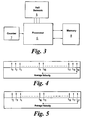
- the output of the sensing means 5 is passed to a processor 6 as shown in Figure 3 of the accompanying drawings.
- the processor 6 also receives a count signal from a timer 7. Each time an event occurs in the output of the Hall effect sensors 5 it is passed to the processor.
- the time at which the event occurred (from t1 to t18) is also stored in the memory in a rolling buffer.
- the processor determines the total time for a complete revolution by summing all the times held in the rolling buffer.
- the average velocity (degrees per second) of the rotor during the revolution is determined by dividing the time (in seconds) by the angle (360 degrees).
- the average velocity could be used to determine the angular displacement between each adjacent event in the buffer by multiplying the elapsed time between events by the average velocity.
- Event n 2 for the second revolution
- the time of the first event is pushed out of the rolling buffer and the new event entered as shown in Figure 5.
- the average velocity of the revolution indicated by the new buffer contents is again calculated. This time the average is used to determine the displacement between the 10 th and 11 th events. This is also stored in the memory. This is shown in Figure 5.
- the process of measurement is continued 18 times until the angular displacements between all adjacent pairs of events are stored in the memory. This provides a measure of the relative angular position of each event.
- the complete set of offset error values are used during subsequent operation of the sensor to determine the exact angular velocity of the rotor.
- the time between two events is determined and the angular position at which the events actually occurred is found by identifying the events.
- the velocity can then be directly found by combing the displacement between events with the elapsed time between events.
Landscapes
- Physics & Mathematics (AREA)
- General Physics & Mathematics (AREA)
- Control Of Motors That Do Not Use Commutators (AREA)
- Transmission And Conversion Of Sensor Element Output (AREA)
- Measurement Of Length, Angles, Or The Like Using Electric Or Magnetic Means (AREA)
Applications Claiming Priority (3)
| Application Number | Priority Date | Filing Date | Title |
|---|---|---|---|
| GB0129446 | 2001-12-08 | ||
| GBGB0129446.1A GB0129446D0 (en) | 2001-12-08 | 2001-12-08 | Angular velocity sensor |
| PCT/GB2002/005587 WO2003054556A1 (en) | 2001-12-08 | 2002-12-09 | Angular velocity sensor |
Publications (2)
| Publication Number | Publication Date |
|---|---|
| EP1451592A1 EP1451592A1 (en) | 2004-09-01 |
| EP1451592B1 true EP1451592B1 (en) | 2006-09-06 |
Family
ID=9927281
Family Applications (1)
| Application Number | Title | Priority Date | Filing Date |
|---|---|---|---|
| EP02783320A Expired - Lifetime EP1451592B1 (en) | 2001-12-08 | 2002-12-09 | Angular velocity sensor |
Country Status (9)
| Country | Link |
|---|---|
| US (1) | US6958599B2 (enExample) |
| EP (1) | EP1451592B1 (enExample) |
| JP (1) | JP4652688B2 (enExample) |
| KR (1) | KR101034999B1 (enExample) |
| AU (1) | AU2002347387A1 (enExample) |
| DE (1) | DE60214588T2 (enExample) |
| ES (1) | ES2268117T3 (enExample) |
| GB (1) | GB0129446D0 (enExample) |
| WO (1) | WO2003054556A1 (enExample) |
Families Citing this family (14)
| Publication number | Priority date | Publication date | Assignee | Title |
|---|---|---|---|---|
| DE102004013234A1 (de) * | 2003-03-21 | 2004-09-30 | Aft Atlas Fahrzeugtechnik Gmbh | Messsystem |
| DE102005019515C5 (de) | 2004-05-15 | 2017-11-16 | Schaeffler Technologies AG & Co. KG | Verfahren zum Messen der Drehzahl eines EC-Motors |
| EP2058628A3 (en) * | 2007-11-06 | 2016-12-21 | GM Global Technology Operations LLC | Method and apparatus to monitor position of a rotatable shaft |
| JP5436191B2 (ja) * | 2009-12-21 | 2014-03-05 | Ntn株式会社 | インホイール型モータ内蔵センサ付き車輪用軸受装置 |
| DE102010062273A1 (de) | 2010-12-01 | 2012-06-06 | Continental Teves Ag & Co. Ohg | Verfahren zur Bestimmung der Drehzahl einer Synchronmaschine |
| FR2988362B1 (fr) * | 2012-03-20 | 2014-09-19 | Alstom Transport Sa | Procede de controle du fonctionnement d'un systeme de positionnement d'un train |
| WO2014199018A1 (en) * | 2013-06-12 | 2014-12-18 | Wärtsilä Finland Oy | Determination of angular speed in an engine |
| US9746511B2 (en) * | 2015-11-25 | 2017-08-29 | Hitachi, Ltd. | Estimating the locations of power system events using PMU measurements |
| EP3217531A1 (de) * | 2016-03-07 | 2017-09-13 | HILTI Aktiengesellschaft | Handwerkzeugmaschine und drehwinkelkorrekturverfahren |
| US10044302B2 (en) * | 2017-01-06 | 2018-08-07 | Honeywell International Inc. | Methods and apparatus for multi-mode motor speed calculation using digital hall effect sensors |
| FR3101704B1 (fr) * | 2019-10-08 | 2021-09-24 | Robert Bosch Automotive Steering Vendome | Procédé de détection d’une position angulaire absolue ou d’une course de déplacement angulaire absolue d’un organe tournant |
| FR3121984B1 (fr) * | 2021-04-14 | 2023-04-14 | Vitesco Technologies | Procédé pour s’adapter aux tolérances d’un système comportant un capteur de position et une cible tournante |
| GB2623762B (en) * | 2022-10-24 | 2025-04-23 | Dalmatic Tnv As | A rotary encoder |
| DE102023136148B4 (de) * | 2023-12-20 | 2025-10-23 | Danfoss Power Solutions Gmbh & Co. Ohg | Verbesserter Drehzahlsensorring |
Family Cites Families (10)
| Publication number | Priority date | Publication date | Assignee | Title |
|---|---|---|---|---|
| GB2184305B (en) * | 1985-12-12 | 1990-03-21 | Gen Electric | Propeller speed measurement |
| JP2799571B2 (ja) * | 1987-07-22 | 1998-09-17 | トヨタ自動車株式会社 | 速度検出装置 |
| JP2929307B2 (ja) * | 1990-02-09 | 1999-08-03 | ココリサーチ株式会社 | 角度測定方法及び速度計測装置 |
| US5258735A (en) * | 1991-10-28 | 1993-11-02 | Allwine Jr Elmer C | Multi-pole composite magnet used in a magnetic encoder |
| JP3221308B2 (ja) * | 1996-01-29 | 2001-10-22 | 株式会社デンソー | 回転センサの非規格要素補償装置 |
| DE19735313B4 (de) * | 1997-08-14 | 2008-02-07 | Bayerische Motoren Werke Ag | Verfahren zur Ermittlung von geschwindigkeitsunabhängigen Frequenzen eines Nutzsignalanteils |
| DE19747918A1 (de) * | 1997-08-25 | 1999-03-11 | Mannesmann Vdo Ag | Verfahren und Anordnung zur genauen Bestimmung der Geschwindigkeit eines umlaufenden Bauteiles, insbesondere der Geschwindigkeit eines Fahrzeugrades |
| US5977764A (en) * | 1997-12-05 | 1999-11-02 | Ford Global Technologies, Inc. | Method to sense speed, direction and acceleration for a rotating shaft using a rotor with unequal tooth spacing |
| WO2000008475A1 (de) * | 1998-08-05 | 2000-02-17 | Siemens Aktiengesellschaft | Motorischer fensterheber- bzw. schiebedachantrieb in einem kraftfahrzeug |
| DE19949106C2 (de) * | 1999-10-12 | 2002-07-18 | Roland Man Druckmasch | Verfahren zur Drehzahlmessung und Vorrichtung zur Durchführung des Verfahrens |
-
2001
- 2001-12-08 GB GBGB0129446.1A patent/GB0129446D0/en not_active Ceased
-
2002
- 2002-12-09 AU AU2002347387A patent/AU2002347387A1/en not_active Abandoned
- 2002-12-09 DE DE60214588T patent/DE60214588T2/de not_active Expired - Lifetime
- 2002-12-09 WO PCT/GB2002/005587 patent/WO2003054556A1/en not_active Ceased
- 2002-12-09 EP EP02783320A patent/EP1451592B1/en not_active Expired - Lifetime
- 2002-12-09 ES ES02783320T patent/ES2268117T3/es not_active Expired - Lifetime
- 2002-12-09 JP JP2003555218A patent/JP4652688B2/ja not_active Expired - Fee Related
- 2002-12-09 KR KR1020047008395A patent/KR101034999B1/ko not_active Expired - Fee Related
-
2004
- 2004-06-08 US US10/863,005 patent/US6958599B2/en not_active Expired - Lifetime
Also Published As
| Publication number | Publication date |
|---|---|
| DE60214588T2 (de) | 2007-05-31 |
| JP4652688B2 (ja) | 2011-03-16 |
| KR101034999B1 (ko) | 2011-05-17 |
| JP2005513483A (ja) | 2005-05-12 |
| US20040251894A1 (en) | 2004-12-16 |
| EP1451592A1 (en) | 2004-09-01 |
| ES2268117T3 (es) | 2007-03-16 |
| GB0129446D0 (en) | 2002-01-30 |
| KR20040070200A (ko) | 2004-08-06 |
| WO2003054556A1 (en) | 2003-07-03 |
| AU2002347387A1 (en) | 2003-07-09 |
| US6958599B2 (en) | 2005-10-25 |
| DE60214588D1 (de) | 2006-10-19 |
Similar Documents
| Publication | Publication Date | Title |
|---|---|---|
| EP1451592B1 (en) | Angular velocity sensor | |
| EP3019832B1 (en) | Rotary encoder post-processing apparatus and rotary encoder | |
| US7049776B2 (en) | Rotor-position sensor assembly and method for detecting a rotor position | |
| KR100701046B1 (ko) | 파워 스티어링 시스템 | |
| CN102859328B (zh) | 用于系统地处理误差的方法 | |
| JP2005513483A5 (enExample) | ||
| CN102893132A (zh) | 用于处理代表发动机的轴的角位置的信号的设备和方法 | |
| JP5172833B2 (ja) | Acサーボモータの回転位置検出方法および簡易エンコーダ | |
| JPH0364809B2 (enExample) | ||
| US7135860B2 (en) | Variable reluctance resolver including rotor with multiple detection portions | |
| US7786686B2 (en) | Method and device for estimating the angular position of the rotor of a brushless motor | |
| US11988530B2 (en) | Method for detecting an absolute angular position or an absolute angular movement path of a rotating member | |
| CN113847935B (zh) | 混合编码器的位置确定方法及装置 | |
| CN117222866A (zh) | 用于适配包括位置传感器和旋转目标的系统的公差的方法 | |
| KR101345305B1 (ko) | 자극 검출 소자 및 이를 이용한 엔코더 | |
| JP3860324B2 (ja) | モータ速度制御装置 | |
| JPS59180319A (ja) | 増分形変位測定装置 | |
| JPH10170307A (ja) | 回転電機の磁極位置検出装置 | |
| JPH0725698Y2 (ja) | 回転機の速度検出装置 | |
| KR20000055856A (ko) | 차량용 영구 자석형 동기 모터의 회전자 위치 검출 방법 | |
| JPH0797004B2 (ja) | アブソリュート位置の検知装置 | |
| JPH06230019A (ja) | 位置速度検出回路 | |
| JPH0469079A (ja) | モータ速度検出装置 | |
| JPH10304700A (ja) | ステッピングモータの脱調検出装置 | |
| JPS6291808A (ja) | 回転体の回転角算出方法 |
Legal Events
| Date | Code | Title | Description |
|---|---|---|---|
| PUAI | Public reference made under article 153(3) epc to a published international application that has entered the european phase |
Free format text: ORIGINAL CODE: 0009012 |
|
| 17P | Request for examination filed |
Effective date: 20040623 |
|
| AK | Designated contracting states |
Kind code of ref document: A1 Designated state(s): AT BE BG CH CY CZ DE DK EE ES FI FR GB GR IE IT LI LU MC NL PT SE SI SK TR |
|
| AX | Request for extension of the european patent |
Extension state: AL LT LV MK RO |
|
| GRAP | Despatch of communication of intention to grant a patent |
Free format text: ORIGINAL CODE: EPIDOSNIGR1 |
|
| GRAS | Grant fee paid |
Free format text: ORIGINAL CODE: EPIDOSNIGR3 |
|
| GRAA | (expected) grant |
Free format text: ORIGINAL CODE: 0009210 |
|
| AK | Designated contracting states |
Kind code of ref document: B1 Designated state(s): DE ES FR GB IT |
|
| REG | Reference to a national code |
Ref country code: GB Ref legal event code: FG4D |
|
| REF | Corresponds to: |
Ref document number: 60214588 Country of ref document: DE Date of ref document: 20061019 Kind code of ref document: P |
|
| ET | Fr: translation filed | ||
| REG | Reference to a national code |
Ref country code: ES Ref legal event code: FG2A Ref document number: 2268117 Country of ref document: ES Kind code of ref document: T3 |
|
| PLBE | No opposition filed within time limit |
Free format text: ORIGINAL CODE: 0009261 |
|
| STAA | Information on the status of an ep patent application or granted ep patent |
Free format text: STATUS: NO OPPOSITION FILED WITHIN TIME LIMIT |
|
| 26N | No opposition filed |
Effective date: 20070607 |
|
| REG | Reference to a national code |
Ref country code: GB Ref legal event code: 732E |
|
| REG | Reference to a national code |
Ref country code: FR Ref legal event code: PLFP Year of fee payment: 14 |
|
| REG | Reference to a national code |
Ref country code: FR Ref legal event code: PLFP Year of fee payment: 15 |
|
| PG25 | Lapsed in a contracting state [announced via postgrant information from national office to epo] |
Ref country code: IT Free format text: LAPSE BECAUSE OF NON-PAYMENT OF DUE FEES Effective date: 20151209 |
|
| PG25 | Lapsed in a contracting state [announced via postgrant information from national office to epo] |
Ref country code: IT Free format text: LAPSE BECAUSE OF NON-PAYMENT OF DUE FEES Effective date: 20151209 |
|
| PGRI | Patent reinstated in contracting state [announced from national office to epo] |
Ref country code: IT Effective date: 20170710 |
|
| REG | Reference to a national code |
Ref country code: FR Ref legal event code: PLFP Year of fee payment: 16 |
|
| PGFP | Annual fee paid to national office [announced via postgrant information from national office to epo] |
Ref country code: NO Payment date: 20181029 Year of fee payment: 11 |
|
| PGFP | Annual fee paid to national office [announced via postgrant information from national office to epo] |
Ref country code: ES Payment date: 20190102 Year of fee payment: 17 |
|
| PGFP | Annual fee paid to national office [announced via postgrant information from national office to epo] |
Ref country code: IT Payment date: 20191219 Year of fee payment: 18 |
|
| PG25 | Lapsed in a contracting state [announced via postgrant information from national office to epo] |
Ref country code: FR Free format text: LAPSE BECAUSE OF NON-PAYMENT OF DUE FEES Effective date: 20191231 |
|
| REG | Reference to a national code |
Ref country code: ES Ref legal event code: FD2A Effective date: 20210526 |
|
| PG25 | Lapsed in a contracting state [announced via postgrant information from national office to epo] |
Ref country code: ES Free format text: LAPSE BECAUSE OF NON-PAYMENT OF DUE FEES Effective date: 20191210 |
|
| PGFP | Annual fee paid to national office [announced via postgrant information from national office to epo] |
Ref country code: DE Payment date: 20211227 Year of fee payment: 20 Ref country code: GB Payment date: 20211227 Year of fee payment: 20 |
|
| REG | Reference to a national code |
Ref country code: DE Ref legal event code: R071 Ref document number: 60214588 Country of ref document: DE |
|
| REG | Reference to a national code |
Ref country code: GB Ref legal event code: PE20 Expiry date: 20221208 |
|
| PG25 | Lapsed in a contracting state [announced via postgrant information from national office to epo] |
Ref country code: GB Free format text: LAPSE BECAUSE OF EXPIRATION OF PROTECTION Effective date: 20221208 |
|
| PG25 | Lapsed in a contracting state [announced via postgrant information from national office to epo] |
Ref country code: IT Free format text: LAPSE BECAUSE OF NON-PAYMENT OF DUE FEES Effective date: 20211231 |
|
| PG25 | Lapsed in a contracting state [announced via postgrant information from national office to epo] |
Ref country code: IT Free format text: LAPSE BECAUSE OF NON-PAYMENT OF DUE FEES Effective date: 20201209 |