EP1450591A2 - Dispositif de fixation détachable pour un module électronique - Google Patents
Dispositif de fixation détachable pour un module électronique Download PDFInfo
- Publication number
- EP1450591A2 EP1450591A2 EP03104762A EP03104762A EP1450591A2 EP 1450591 A2 EP1450591 A2 EP 1450591A2 EP 03104762 A EP03104762 A EP 03104762A EP 03104762 A EP03104762 A EP 03104762A EP 1450591 A2 EP1450591 A2 EP 1450591A2
- Authority
- EP
- European Patent Office
- Prior art keywords
- module
- side wall
- fastening device
- sheet metal
- metal frame
- Prior art date
- Legal status (The legal status is an assumption and is not a legal conclusion. Google has not performed a legal analysis and makes no representation as to the accuracy of the status listed.)
- Granted
Links
Images


Classifications
-
- H—ELECTRICITY
- H05—ELECTRIC TECHNIQUES NOT OTHERWISE PROVIDED FOR
- H05K—PRINTED CIRCUITS; CASINGS OR CONSTRUCTIONAL DETAILS OF ELECTRIC APPARATUS; MANUFACTURE OF ASSEMBLAGES OF ELECTRICAL COMPONENTS
- H05K7/00—Constructional details common to different types of electric apparatus
- H05K7/14—Mounting supporting structure in casing or on frame or rack
-
- H—ELECTRICITY
- H05—ELECTRIC TECHNIQUES NOT OTHERWISE PROVIDED FOR
- H05K—PRINTED CIRCUITS; CASINGS OR CONSTRUCTIONAL DETAILS OF ELECTRIC APPARATUS; MANUFACTURE OF ASSEMBLAGES OF ELECTRICAL COMPONENTS
- H05K5/00—Casings, cabinets or drawers for electric apparatus
- H05K5/02—Details
- H05K5/0204—Mounting supporting structures on the outside of casings
Definitions
- the invention relates to a detachable Fastening device for an electronic module, especially for a GPS receiver of a motor vehicle a side wall of a sheet metal frame, with an approximately box-like housing of the module, of which a connecting part, in particular an antenna connector protrudes and through a connection opening of a wall of the sheet metal frame protrudes with protruding from the box-shaped housing Fixing elements in the mounting position of the module the sheet metal frame through fixing openings in the side wall of the Sheet metal frame protrude and with radial extensions on the Surrounding area of the fixing openings around this the side of the side wall of the module facing away from the module with mounting openings in the side wall into which the Fixing openings over extending in the same direction Lead-in areas open, with the radial extensions transverse to the level of the side wall through the mounting holes and the Fixing elements in the plane of the side wall through the Insertion areas can be passed through.
- the module has one end face protruding cylindrical antenna connector that with is provided with an external thread and a slightly smaller one Outer diameter than the diameter of the Connection opening of the rear wall is.
- the module in has on the side facing the side wall its end area facing away from the rear wall corresponding to the Fixing openings with two protruding fixing elements radial extensions at their free ends.
- the Connection part of the module in the connection opening and Fixing elements inserted into the mounting holes. After that the module is moved parallel to the side wall towards the rear wall until the module with its front wall is in contact with the rear wall of the sheet metal frame. Move it the fixing elements at the same time Insertion areas in the fixing openings and lie with their radial extensions on the side facing away from the module the side wall at the surrounding areas of the fixing openings on. From the side of the rear wall facing away from the module Sheet metal frame ago is first a washer on the Antenna connector plugged in and then a union nut screwed onto the external thread of the antenna connector and thus the module with the sheet metal frame in a detachable manner firmly connected.
- the object of the invention is therefore a releasable Fastening device of the type mentioned create where the module is easy to assemble and removable and the connector free of Fixing forces of the module on the sheet metal frame is.
- This training is used to assemble the module its connector in the connector opening and with the Fixing elements transverse to the level of the side wall in the Side wall mounting holes inserted. This happens Spring element and the locking lug under resilient bias on the side wall. Then the module becomes parallel moved to the side wall and the fixing elements arrive through the insertion areas into the fixing openings. In this The fastening position is the catch approach to the catch opening arrives and snapped into this. This ensures that the Snap-in snap-in insert the module in its Mounting position, while the spring element is radial Extensions of the fixing elements under tension against the Surrounding areas of the fixing openings on the module opposite side of the side wall pulls and vibration-free holds securely.
- Disassembly of the module as e.g. for maintenance or to replace the module is also necessary easily possible without special tools.
- End areas of the module each have a spring element and preferably also in each of these end regions Fixing elements and spaced apart Fixing openings are available. It is preferably the Support point of the spring element between two fixing elements positioned.
- the spring element can have several Have spring arms, two of which are opposed each extend to an edge region of the module.
- Attachment points can be attached to the housing of the module.
- connection area about the opposite of each other extending spring arms outside a connecting line arranged between the attachment points, which is easy
- the spring element is approximately U-shaped is formed and two mirror images of each other arranged L-shaped spring arms, in their Connection area of the locking projection is arranged, so form the legs of the "L” of the spring arms attached to the module cantilevered and largely freely resilient Spring arms.
- Spring element a one-piece, in particular made of plastic existing component.
- the fixing elements can be designed like bolts and have a radially circumferential groove, the groove width about the thickness of the side wall of the sheet metal frame and their Diameter at the bottom of the groove approximately the width of the fixing opening and corresponds to the lead-in area.
- the fixing openings with the Insertion areas are formed by elongated holes.
- connection opening be an elongated hole that is approximately parallel to Extension of the insertion areas extends.
- the connecting part can be parallel to the fixing elements extend and a connection opening in the side wall of the Project through the sheet metal frame. However, this preferably extends Connection part approximately parallel to the level of the side wall of the Sheet metal frame and the connection opening is in one Side wall extending approximately at right angles to the rear wall of the Sheet metal frame trained.
- the Sheet metal frame is a stamped / bent component and in particular from a metal.
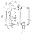
- a metallic sheet metal frame 1 is present in the figures, which consists of an approximately rectangular side wall 2 and one the short side of which is bent back at right angles 3 consists. Furthermore, on the upper long side Sidewall 2 bent a top wall 4 at right angles.
- the fixing openings 5, 5 ', 6, 6' form together with it subsequent insertion areas parallel to the angling of the Rear wall 3 downward elongated holes 7 and 7 ', in Assembly openings 8, 8 'open.
- a long side of the upper elongated holes 7 is transverse to the Elongated holes 7 formed in the side wall 2 slots 9 formed to spring arms 10, the elongated holes 7 directed free ends from the plane of the side wall 2 are turned out.
- the assembly openings 8 'of the lower elongated holes 7' open open at the bottom of the side wall 2 to the outside.
- a connection opening 12 in the form of an elongated hole is arranged, which are approximately parallel to the extension of the elongated holes 7, 7 ' extends and opens outward at its lower end.
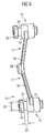
- An electronic module 13 with a rectangular one box-like housing 14 and one on one end face protruding cylindrical connector 15 is at its Longitudinal end regions with spring elements 16 Mistake.
- These spring elements 16 each consist of two Spring arms 17, which are L-shaped and at the ends their long legs 18 are connected together so that they extend in a line.
- the short leg 19 are directed in the same direction so that the one another connected spring arms 17 form a "U".
- the long legs 18 of the spring arms 17 are under one Inclined to each other so that they have a wide open “V” form. At their connection area is on the outer Top of the "V” a locking projection 20 is arranged.
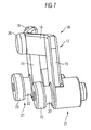
- the area between the groove 22 and the free end of the Fixing element 21 forms a radial extension 25 a circular cross-section that is smaller than the mounting openings 8, 8 'and larger than the fixing openings 5, 5', 6, 6 '.
- the short legs 19 of the spring arms 17 are approximately in middle area of the fixing elements 21 with these firmly connected. With its radial extension 25 opposite ends, the fixing elements 21 are such firmly arranged on the housing 14 of the module 13 that the Connection area of the spring arms 17 the greatest distance has the housing 14 of the module 13.
- the locking inserts 20 snap into place Snap openings 11 of the side wall 2 and hold the module 13 immovable in this position on the side wall 2.
- the fixing elements 21 encompass with their radial Extensions 25 the surrounding areas of the fixing openings 5, 5 ', 6, 6' in the side wall 2, the spring arms 10 for an axially backlash-free mounting of the fixing elements 21 on the Ensure side wall 2.
- the module 13 is the electronic module of a GPS receiver for a navigation device in a motor vehicle, in which the sheet metal frame 1 is fixed, the holder for module 13.
- the connector is a Antenna connector for connecting an antenna to Receive the GPS data.
Landscapes
- Engineering & Computer Science (AREA)
- Microelectronics & Electronic Packaging (AREA)
- Casings For Electric Apparatus (AREA)
Applications Claiming Priority (2)
| Application Number | Priority Date | Filing Date | Title |
|---|---|---|---|
| DE2003106783 DE10306783B4 (de) | 2003-02-18 | 2003-02-18 | Lösbare Befestigungsvorrichtung für ein elektronisches Modul |
| DE10306783 | 2003-02-18 |
Publications (3)
| Publication Number | Publication Date |
|---|---|
| EP1450591A2 true EP1450591A2 (fr) | 2004-08-25 |
| EP1450591A3 EP1450591A3 (fr) | 2008-04-16 |
| EP1450591B1 EP1450591B1 (fr) | 2009-07-01 |
Family
ID=32731036
Family Applications (1)
| Application Number | Title | Priority Date | Filing Date |
|---|---|---|---|
| EP20030104762 Expired - Fee Related EP1450591B1 (fr) | 2003-02-18 | 2003-12-17 | Dispositif de fixation détachable pour un module électronique |
Country Status (2)
| Country | Link |
|---|---|
| EP (1) | EP1450591B1 (fr) |
| DE (2) | DE10306783B4 (fr) |
Cited By (1)
| Publication number | Priority date | Publication date | Assignee | Title |
|---|---|---|---|---|
| EP2242342A3 (fr) * | 2009-04-16 | 2012-04-11 | Wilhelm Sihn Jr. GmbH & Co. KG | Composant électrique |
Citations (3)
| Publication number | Priority date | Publication date | Assignee | Title |
|---|---|---|---|---|
| DE29520061U1 (de) * | 1995-12-18 | 1996-04-18 | Haschkamp Joachim | Schaltgerät |
| EP0810419A2 (fr) * | 1996-05-31 | 1997-12-03 | Aisin Aw Co., Ltd. | Unité de navigation |
| JP2002349943A (ja) * | 2001-05-22 | 2002-12-04 | Noritz Corp | ゴムブッシュ及び換気アダプタ並びにそれらを用いた換気穴に対する換気パイプのシール構造 |
-
2003
- 2003-02-18 DE DE2003106783 patent/DE10306783B4/de not_active Expired - Fee Related
- 2003-12-17 EP EP20030104762 patent/EP1450591B1/fr not_active Expired - Fee Related
- 2003-12-17 DE DE50311657T patent/DE50311657D1/de not_active Expired - Lifetime
Patent Citations (3)
| Publication number | Priority date | Publication date | Assignee | Title |
|---|---|---|---|---|
| DE29520061U1 (de) * | 1995-12-18 | 1996-04-18 | Haschkamp Joachim | Schaltgerät |
| EP0810419A2 (fr) * | 1996-05-31 | 1997-12-03 | Aisin Aw Co., Ltd. | Unité de navigation |
| JP2002349943A (ja) * | 2001-05-22 | 2002-12-04 | Noritz Corp | ゴムブッシュ及び換気アダプタ並びにそれらを用いた換気穴に対する換気パイプのシール構造 |
Cited By (1)
| Publication number | Priority date | Publication date | Assignee | Title |
|---|---|---|---|---|
| EP2242342A3 (fr) * | 2009-04-16 | 2012-04-11 | Wilhelm Sihn Jr. GmbH & Co. KG | Composant électrique |
Also Published As
| Publication number | Publication date |
|---|---|
| EP1450591B1 (fr) | 2009-07-01 |
| DE10306783B4 (de) | 2006-11-09 |
| DE50311657D1 (de) | 2009-08-13 |
| EP1450591A3 (fr) | 2008-04-16 |
| DE10306783A1 (de) | 2004-10-28 |
Similar Documents
| Publication | Publication Date | Title |
|---|---|---|
| DE19806690A1 (de) | Befestigung eines Bauteiles an einem plattenförmigen Tragteil | |
| DE102004017371A1 (de) | Antennenvorrichtung für ein Fahrzeug mit einem als Rastelement ausgebildetem Befestigungselement | |
| EP2703657B1 (fr) | Elément de fixation doté de plusieurs directions d'assemblage et agencement de fixation correspondant pour la fixation d'une pièce rapportée sur une carrosserie de véhicule | |
| DE102014205467B4 (de) | Steckverbindungsanordnung | |
| EP3257121A1 (fr) | Ensemble de plusieurs pieds encliquetables pour module et module | |
| EP0961535A1 (fr) | Dispositif d'entretoisement pour l'appui d'une carte à circuits imprimés à un support électriquement conducteur | |
| EP3133305B1 (fr) | Écrou cage | |
| DE102005049140B4 (de) | Vorrichtung zur Befestigung eines Sensors | |
| DE10210628C1 (de) | Vorrichtung zur spielfreien Ein-Mann Montage eines Anbauteils, oder einer Kfz-Dachantenne | |
| DE19544083C2 (de) | Vorrichtung zum Befestigen von Zusatzeinrichtungen an Hutschienen | |
| DE10348979A1 (de) | Befestigung einer Leiterplatte an einem Gehäuse | |
| EP1450591A2 (fr) | Dispositif de fixation détachable pour un module électronique | |
| WO2004023606A1 (fr) | Borne de traversee | |
| DE4313739A1 (de) | Vorrichtung zum Befestigen eines zweiten Bauteils an einem ersten Bauteil | |
| EP2481967A2 (fr) | Elément de maintien et de serrage pour la fixation réversible de composants, notamment pour le montage au mur ou au plafond de systèmes d'écran | |
| DE19734601A1 (de) | Lochscheibe | |
| DE102016107858B4 (de) | Heckblendenanordnung eines Kraftfahrzeugs | |
| DE19910987C2 (de) | Halterahmen zur Festlegung eines Bauteils an einer Wand | |
| DE4138047A1 (de) | Vorrichtung zum verbinden mehrerer teile | |
| DE102013106451B4 (de) | Lichtmodul mit einem Blendenelement für einen Scheinwerfer eines Fahrzeugs | |
| DE102004027859B4 (de) | Leiterplatte und Leiterplattenvorrichtung | |
| DE102014203337A1 (de) | Elektrisches/elektronisches Gerät, Gehäuseeinrichtung | |
| WO1998051998A1 (fr) | Systeme de mesure | |
| EP3056881A1 (fr) | Detecteur de mouvement a infrarouge passif | |
| EP1724551B1 (fr) | Agencement de support |
Legal Events
| Date | Code | Title | Description |
|---|---|---|---|
| PUAI | Public reference made under article 153(3) epc to a published international application that has entered the european phase |
Free format text: ORIGINAL CODE: 0009012 |
|
| AK | Designated contracting states |
Kind code of ref document: A2 Designated state(s): AT BE BG CH CY CZ DE DK EE ES FI FR GB GR HU IE IT LI LU MC NL PT RO SE SI SK TR |
|
| AX | Request for extension of the european patent |
Extension state: AL LT LV MK |
|
| PUAL | Search report despatched |
Free format text: ORIGINAL CODE: 0009013 |
|
| AK | Designated contracting states |
Kind code of ref document: A3 Designated state(s): AT BE BG CH CY CZ DE DK EE ES FI FR GB GR HU IE IT LI LU MC NL PT RO SE SI SK TR |
|
| AX | Request for extension of the european patent |
Extension state: AL LT LV MK |
|
| RAP1 | Party data changed (applicant data changed or rights of an application transferred) |
Owner name: CONTINENTAL AUTOMOTIVE GMBH |
|
| 17P | Request for examination filed |
Effective date: 20081016 |
|
| AKX | Designation fees paid |
Designated state(s): DE FR GB IT |
|
| GRAP | Despatch of communication of intention to grant a patent |
Free format text: ORIGINAL CODE: EPIDOSNIGR1 |
|
| GRAS | Grant fee paid |
Free format text: ORIGINAL CODE: EPIDOSNIGR3 |
|
| GRAA | (expected) grant |
Free format text: ORIGINAL CODE: 0009210 |
|
| AK | Designated contracting states |
Kind code of ref document: B1 Designated state(s): DE FR GB IT |
|
| REG | Reference to a national code |
Ref country code: GB Ref legal event code: FG4D Free format text: NOT ENGLISH |
|
| REF | Corresponds to: |
Ref document number: 50311657 Country of ref document: DE Date of ref document: 20090813 Kind code of ref document: P |
|
| PLBE | No opposition filed within time limit |
Free format text: ORIGINAL CODE: 0009261 |
|
| STAA | Information on the status of an ep patent application or granted ep patent |
Free format text: STATUS: NO OPPOSITION FILED WITHIN TIME LIMIT |
|
| 26N | No opposition filed |
Effective date: 20100406 |
|
| PGFP | Annual fee paid to national office [announced via postgrant information from national office to epo] |
Ref country code: IT Payment date: 20121219 Year of fee payment: 10 Ref country code: GB Payment date: 20121220 Year of fee payment: 10 |
|
| GBPC | Gb: european patent ceased through non-payment of renewal fee |
Effective date: 20131217 |
|
| PG25 | Lapsed in a contracting state [announced via postgrant information from national office to epo] |
Ref country code: GB Free format text: LAPSE BECAUSE OF NON-PAYMENT OF DUE FEES Effective date: 20131217 |
|
| PG25 | Lapsed in a contracting state [announced via postgrant information from national office to epo] |
Ref country code: IT Free format text: LAPSE BECAUSE OF NON-PAYMENT OF DUE FEES Effective date: 20131231 |
|
| REG | Reference to a national code |
Ref country code: FR Ref legal event code: PLFP Year of fee payment: 13 |
|
| PG25 | Lapsed in a contracting state [announced via postgrant information from national office to epo] |
Ref country code: IT Free format text: LAPSE BECAUSE OF NON-PAYMENT OF DUE FEES Effective date: 20131217 |
|
| REG | Reference to a national code |
Ref country code: FR Ref legal event code: PLFP Year of fee payment: 14 |
|
| PGFP | Annual fee paid to national office [announced via postgrant information from national office to epo] |
Ref country code: FR Payment date: 20161222 Year of fee payment: 14 |
|
| PGFP | Annual fee paid to national office [announced via postgrant information from national office to epo] |
Ref country code: DE Payment date: 20161231 Year of fee payment: 14 |
|
| REG | Reference to a national code |
Ref country code: DE Ref legal event code: R119 Ref document number: 50311657 Country of ref document: DE |
|
| REG | Reference to a national code |
Ref country code: FR Ref legal event code: ST Effective date: 20180831 |
|
| PG25 | Lapsed in a contracting state [announced via postgrant information from national office to epo] |
Ref country code: DE Free format text: LAPSE BECAUSE OF NON-PAYMENT OF DUE FEES Effective date: 20180703 Ref country code: FR Free format text: LAPSE BECAUSE OF NON-PAYMENT OF DUE FEES Effective date: 20180102 |