EP1450591A2 - Releasable fastening device for electronic modul - Google Patents
Releasable fastening device for electronic modul Download PDFInfo
- Publication number
- EP1450591A2 EP1450591A2 EP03104762A EP03104762A EP1450591A2 EP 1450591 A2 EP1450591 A2 EP 1450591A2 EP 03104762 A EP03104762 A EP 03104762A EP 03104762 A EP03104762 A EP 03104762A EP 1450591 A2 EP1450591 A2 EP 1450591A2
- Authority
- EP
- European Patent Office
- Prior art keywords
- module
- side wall
- fastening device
- sheet metal
- metal frame
- Prior art date
- Legal status (The legal status is an assumption and is not a legal conclusion. Google has not performed a legal analysis and makes no representation as to the accuracy of the status listed.)
- Granted
Links
Images


Classifications
-
- H—ELECTRICITY
- H05—ELECTRIC TECHNIQUES NOT OTHERWISE PROVIDED FOR
- H05K—PRINTED CIRCUITS; CASINGS OR CONSTRUCTIONAL DETAILS OF ELECTRIC APPARATUS; MANUFACTURE OF ASSEMBLAGES OF ELECTRICAL COMPONENTS
- H05K7/00—Constructional details common to different types of electric apparatus
- H05K7/14—Mounting supporting structure in casing or on frame or rack
-
- H—ELECTRICITY
- H05—ELECTRIC TECHNIQUES NOT OTHERWISE PROVIDED FOR
- H05K—PRINTED CIRCUITS; CASINGS OR CONSTRUCTIONAL DETAILS OF ELECTRIC APPARATUS; MANUFACTURE OF ASSEMBLAGES OF ELECTRICAL COMPONENTS
- H05K5/00—Casings, cabinets or drawers for electric apparatus
- H05K5/02—Details
- H05K5/0204—Mounting supporting structures on the outside of casings
Definitions
- the invention relates to a detachable Fastening device for an electronic module, especially for a GPS receiver of a motor vehicle a side wall of a sheet metal frame, with an approximately box-like housing of the module, of which a connecting part, in particular an antenna connector protrudes and through a connection opening of a wall of the sheet metal frame protrudes with protruding from the box-shaped housing Fixing elements in the mounting position of the module the sheet metal frame through fixing openings in the side wall of the Sheet metal frame protrude and with radial extensions on the Surrounding area of the fixing openings around this the side of the side wall of the module facing away from the module with mounting openings in the side wall into which the Fixing openings over extending in the same direction Lead-in areas open, with the radial extensions transverse to the level of the side wall through the mounting holes and the Fixing elements in the plane of the side wall through the Insertion areas can be passed through.
- the module has one end face protruding cylindrical antenna connector that with is provided with an external thread and a slightly smaller one Outer diameter than the diameter of the Connection opening of the rear wall is.
- the module in has on the side facing the side wall its end area facing away from the rear wall corresponding to the Fixing openings with two protruding fixing elements radial extensions at their free ends.
- the Connection part of the module in the connection opening and Fixing elements inserted into the mounting holes. After that the module is moved parallel to the side wall towards the rear wall until the module with its front wall is in contact with the rear wall of the sheet metal frame. Move it the fixing elements at the same time Insertion areas in the fixing openings and lie with their radial extensions on the side facing away from the module the side wall at the surrounding areas of the fixing openings on. From the side of the rear wall facing away from the module Sheet metal frame ago is first a washer on the Antenna connector plugged in and then a union nut screwed onto the external thread of the antenna connector and thus the module with the sheet metal frame in a detachable manner firmly connected.
- the object of the invention is therefore a releasable Fastening device of the type mentioned create where the module is easy to assemble and removable and the connector free of Fixing forces of the module on the sheet metal frame is.
- This training is used to assemble the module its connector in the connector opening and with the Fixing elements transverse to the level of the side wall in the Side wall mounting holes inserted. This happens Spring element and the locking lug under resilient bias on the side wall. Then the module becomes parallel moved to the side wall and the fixing elements arrive through the insertion areas into the fixing openings. In this The fastening position is the catch approach to the catch opening arrives and snapped into this. This ensures that the Snap-in snap-in insert the module in its Mounting position, while the spring element is radial Extensions of the fixing elements under tension against the Surrounding areas of the fixing openings on the module opposite side of the side wall pulls and vibration-free holds securely.
- Disassembly of the module as e.g. for maintenance or to replace the module is also necessary easily possible without special tools.
- End areas of the module each have a spring element and preferably also in each of these end regions Fixing elements and spaced apart Fixing openings are available. It is preferably the Support point of the spring element between two fixing elements positioned.
- the spring element can have several Have spring arms, two of which are opposed each extend to an edge region of the module.
- Attachment points can be attached to the housing of the module.
- connection area about the opposite of each other extending spring arms outside a connecting line arranged between the attachment points, which is easy
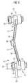
- the spring element is approximately U-shaped is formed and two mirror images of each other arranged L-shaped spring arms, in their Connection area of the locking projection is arranged, so form the legs of the "L” of the spring arms attached to the module cantilevered and largely freely resilient Spring arms.
- Spring element a one-piece, in particular made of plastic existing component.
- the fixing elements can be designed like bolts and have a radially circumferential groove, the groove width about the thickness of the side wall of the sheet metal frame and their Diameter at the bottom of the groove approximately the width of the fixing opening and corresponds to the lead-in area.
- the fixing openings with the Insertion areas are formed by elongated holes.
- connection opening be an elongated hole that is approximately parallel to Extension of the insertion areas extends.
- the connecting part can be parallel to the fixing elements extend and a connection opening in the side wall of the Project through the sheet metal frame. However, this preferably extends Connection part approximately parallel to the level of the side wall of the Sheet metal frame and the connection opening is in one Side wall extending approximately at right angles to the rear wall of the Sheet metal frame trained.
- the Sheet metal frame is a stamped / bent component and in particular from a metal.
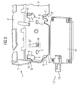
- a metallic sheet metal frame 1 is present in the figures, which consists of an approximately rectangular side wall 2 and one the short side of which is bent back at right angles 3 consists. Furthermore, on the upper long side Sidewall 2 bent a top wall 4 at right angles.
- the fixing openings 5, 5 ', 6, 6' form together with it subsequent insertion areas parallel to the angling of the Rear wall 3 downward elongated holes 7 and 7 ', in Assembly openings 8, 8 'open.
- a long side of the upper elongated holes 7 is transverse to the Elongated holes 7 formed in the side wall 2 slots 9 formed to spring arms 10, the elongated holes 7 directed free ends from the plane of the side wall 2 are turned out.
- the assembly openings 8 'of the lower elongated holes 7' open open at the bottom of the side wall 2 to the outside.
- a connection opening 12 in the form of an elongated hole is arranged, which are approximately parallel to the extension of the elongated holes 7, 7 ' extends and opens outward at its lower end.
- An electronic module 13 with a rectangular one box-like housing 14 and one on one end face protruding cylindrical connector 15 is at its Longitudinal end regions with spring elements 16 Mistake.
- These spring elements 16 each consist of two Spring arms 17, which are L-shaped and at the ends their long legs 18 are connected together so that they extend in a line.
- the short leg 19 are directed in the same direction so that the one another connected spring arms 17 form a "U".
- the long legs 18 of the spring arms 17 are under one Inclined to each other so that they have a wide open “V” form. At their connection area is on the outer Top of the "V” a locking projection 20 is arranged.
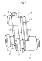
- the area between the groove 22 and the free end of the Fixing element 21 forms a radial extension 25 a circular cross-section that is smaller than the mounting openings 8, 8 'and larger than the fixing openings 5, 5', 6, 6 '.
- the short legs 19 of the spring arms 17 are approximately in middle area of the fixing elements 21 with these firmly connected. With its radial extension 25 opposite ends, the fixing elements 21 are such firmly arranged on the housing 14 of the module 13 that the Connection area of the spring arms 17 the greatest distance has the housing 14 of the module 13.
- the locking inserts 20 snap into place Snap openings 11 of the side wall 2 and hold the module 13 immovable in this position on the side wall 2.
- the fixing elements 21 encompass with their radial Extensions 25 the surrounding areas of the fixing openings 5, 5 ', 6, 6' in the side wall 2, the spring arms 10 for an axially backlash-free mounting of the fixing elements 21 on the Ensure side wall 2.
- the module 13 is the electronic module of a GPS receiver for a navigation device in a motor vehicle, in which the sheet metal frame 1 is fixed, the holder for module 13.
- the connector is a Antenna connector for connecting an antenna to Receive the GPS data.
Abstract
Description
Die Erfindung bezieht sich auf eine lösbare Befestigungsvorrichtung für ein elektronisches Modul, insbesondere für einen GPS-Empfänger eines Kraftfahrzeugs, an einer Seitenwand eines Blechrahmens, mit einem etwa kastenartigen Gehäuse des Moduls, von dem ein Anschlußteil, insbesondere ein Antennenanschlußteil hervorsteht und durch eine Anschlußöffnung einer Wand des Blechrahmens ragt, mit von dem kastenförmigen Gehäuse hervorstehenden Fixierelementen, die in der Befestigungslage des Moduls an dem Blechrahmen durch Fixieröffnungen in der Seitenwand des Blechrahmens ragen und mit radialen Erweiterungen an dem Umgebungsbereich der Fixieröffnungen diesen umgreifend auf der dem Modul abgewandten Seite der Seitenwand des Moduls anliegen, mit Montageöffnungen in der Seitenwand, in die die Fixieröffnungen über in gleiche Richtung sich erstreckende Einführbereiche münden, wobei die radialen Erweiterungen quer zur Ebene der Seitenwand durch die Montageöffnungen und die Fixierelemente in der Ebene der Seitenwand durch die Einführbereiche hindurchführbar sind.The invention relates to a detachable Fastening device for an electronic module, especially for a GPS receiver of a motor vehicle a side wall of a sheet metal frame, with an approximately box-like housing of the module, of which a connecting part, in particular an antenna connector protrudes and through a connection opening of a wall of the sheet metal frame protrudes with protruding from the box-shaped housing Fixing elements in the mounting position of the module the sheet metal frame through fixing openings in the side wall of the Sheet metal frame protrude and with radial extensions on the Surrounding area of the fixing openings around this the side of the side wall of the module facing away from the module with mounting openings in the side wall into which the Fixing openings over extending in the same direction Lead-in areas open, with the radial extensions transverse to the level of the side wall through the mounting holes and the Fixing elements in the plane of the side wall through the Insertion areas can be passed through.
Bei einer derartigen Befestigungsvorrichtung ist es bekannt, daß in einer etwa rechtwinklig zur Seitenwand eines Blechrahmens sich erstreckenden Rückwand des Blechrahmens die Anschlußöffnung als Bohrung ausgebildet ist. In einem Abstand von der Rückwand sind an der Seitenwand im Abstand zueinander zwei Fixieröffnungen ausgebildet, von denen in von der Rückwand entfernender Richtung Einführöffnungen zu Montageöffnungen führen. With such a fastening device it is known that in a roughly perpendicular to the side wall of a Sheet metal frame extending rear wall of the sheet metal frame Connection opening is designed as a bore. At a distance from the back wall are on the side wall at a distance from each other two fixing openings are formed, of which in from the Rear wall towards the insertion openings Lead assembly openings.
Das Modul besitzt an seiner einen Stirnseite ein hervorstehendes zylindrisches Antennenanschlußteil, das mit einem Außengewinde versehen ist und einen etwas geringeren Außendurchmesser besitzt, als es der Durchmesser der Anschlußöffnung der Rückwand ist.The module has one end face protruding cylindrical antenna connector that with is provided with an external thread and a slightly smaller one Outer diameter than the diameter of the Connection opening of the rear wall is.
An der der Seitenwand zugewandten Seite besitzt das Modul in seinem der Rückwand abgewandten Endbereich entsprechend der Fixieröffnungen zwei hervorstehende Fixierelemente mit radialen Erweiterungen an ihren freien Enden.The module in has on the side facing the side wall its end area facing away from the rear wall corresponding to the Fixing openings with two protruding fixing elements radial extensions at their free ends.
Zur Befestigung des Moduls am Blechrahmen werden das Anschlußteil des Moduls in die Anschlußöffnung und die Fixierelemente in die Montageöffnungen eingeführt. Danach erfolgt eine Verschiebung des Moduls parallel zur Seitenwand in Richtung zur Rückwand, bis das Modul mit seiner Stirnwand in Anlage an der Rückwand des Blechrahmens ist. Dabei bewegen sich gleichzeitig die Fixierelemente durch die Einführbereiche in die Fixieröffnungen und liegen mit ihren radialen Erweiterungen auf der dem Modul abgewandten Seite der Seitenwand an den Umgebungsbereichen der Fixieröffnungen an. Von der dem Modul abgewandten Seite der Rückwand des Blechrahmens her wird zunächst eine Unterlegscheibe auf das Antennenanschlußteil aufgesteckt und dann eine Überwurfmutter auf das Außengewinde des Antennenanschlußteils aufgeschraubt und damit das Modul mit dem Blechrahmen auf lösbare Weise fest verbunden.To attach the module to the sheet metal frame, the Connection part of the module in the connection opening and Fixing elements inserted into the mounting holes. After that the module is moved parallel to the side wall towards the rear wall until the module with its front wall is in contact with the rear wall of the sheet metal frame. Move it the fixing elements at the same time Insertion areas in the fixing openings and lie with their radial extensions on the side facing away from the module the side wall at the surrounding areas of the fixing openings on. From the side of the rear wall facing away from the module Sheet metal frame ago is first a washer on the Antenna connector plugged in and then a union nut screwed onto the external thread of the antenna connector and thus the module with the sheet metal frame in a detachable manner firmly connected.
Diese Ausbildung benötigt viele Bauteile und einen großen Montageaufwand.This training requires many components and a large one Installation effort.
Darüber hinaus wird das Anschlußteil mit erheblichen Kräften durch die Überwurfmutter beaufschlagt. Weiterhin bildet das Antennenanschlußteil gleichzeitig ein Befestigungselement des Moduls und wird somit durch alle auf das Modul einwirkenden Kräfte ebenfalls belastet.In addition, the connector with considerable force acted upon by the union nut. Furthermore, that forms Antenna connector is also a fastener of the Module and is thus influenced by everyone acting on the module Forces also burdened.
Aufgabe der Erfindung ist es daher eine lösbare Befestigungsvorrichtung der eingangs genannten Art zu schaffen, bei der das Modul einfach montierbar und demontierbar sowie das Anschlußteil frei von Befestigungskräften des Moduls am Blechrahmen ist.The object of the invention is therefore a releasable Fastening device of the type mentioned create where the module is easy to assemble and removable and the connector free of Fixing forces of the module on the sheet metal frame is.
Diese Aufgabe wird erfindungsgemäß dadurch gelöst, daß an dem Gehäuse des Moduls wenigstens ein Federelement angeordnet ist, das unter federnder Vorspannung an der dem Modul zugewandten Fläche der Seitenwand abstützbar ist und einen zur Seitenwand gerichteten Rastansatz besitzt, der in der Befestigungslage federnd in eine Rastöffnung etwa entsprechenden Querschnitts des Blechrahmens eingerastet ist.This object is achieved in that the Housing of the module arranged at least one spring element is under spring tension on the module facing surface of the side wall is supported and a has to the side wall facing latching lug in the Fixing position resiliently in a latching opening corresponding cross-section of the sheet metal frame is engaged.
Durch diese Ausbildung wird zur Montage des Moduls dieses mit seinem Anschlußteil in die Anschlußöffnung und mit den Fixierelementen quer zur Ebene der Seitenwand in die Montageöffnungen der Seitenwand eingeführt. Dabei gelangt das Federelement und der Rastansatz unter federnder Vorspannung zur Anlage an der Seitenwand. Danach wird das Modul parallel zur Seitenwand verschoben und die Fixierelemente gelangen durch die Einführbereiche in die Fixieröffnungen. In dieser Befestigungslage ist der Rastansatz zu der Rastöffnung gelangt und in diese eingerastet. Damit sichert der in die Rastöffnung eingerastete Rasteinsatz das Modul in seiner Befestigungslage, während das Federelement die radialen Erweiterungen der Fixierelemente unter Vorspannung gegen die Umgebungsbereiche der Fixieröffnungen auf der dem Modul abgewandten Seite der Seitenwand zieht und erschütterungsfrei sicher hält.This training is used to assemble the module its connector in the connector opening and with the Fixing elements transverse to the level of the side wall in the Side wall mounting holes inserted. This happens Spring element and the locking lug under resilient bias on the side wall. Then the module becomes parallel moved to the side wall and the fixing elements arrive through the insertion areas into the fixing openings. In this The fastening position is the catch approach to the catch opening arrives and snapped into this. This ensures that the Snap-in snap-in insert the module in its Mounting position, while the spring element is radial Extensions of the fixing elements under tension against the Surrounding areas of the fixing openings on the module opposite side of the side wall pulls and vibration-free holds securely.
Da das Federelement und der Rastansatz vormontierbar sind, werden zum Einbau des Moduls in den Blechrahmen keine weiteren Bauteile benötigt, so daß über ein einfaches Aufstecken und Einrasten eine kostengünstige Montage des Moduls erfolgt. Dabei bleibt das Anschlußteil völlig frei von irgendwelchen Montage- und Haltekräften.Since the spring element and the locking lug can be preassembled, are not used to install the module in the sheet metal frame other components needed, so that a simple Attach and snap in an inexpensive installation of the Module. The connector remains completely free of any assembly and holding forces.
Eine Demontage des Moduls, wie sie z.B. zu einer Wartung oder zu einem Austausch des Moduls erforderlich ist, ist ebenfalls ohne besondere Werkzeuge auf einfache Weise möglich.Disassembly of the module as e.g. for maintenance or to replace the module is also necessary easily possible without special tools.
Um eine gleichmäßige Abstützung des Moduls an der Seitenwand zu erreichen, kann in den einander entgegengesetzten Endbereichen des Moduls jeweils ein Federelement angeordnet und vorzugsweise in diesen Endbereichen auch jeweils zwei im Abstand zueinander angeordnete Fixierelemente und Fixieröffnungen vorhanden sein. Dabei ist vorzugsweise die Abstützstelle des Federelements zwischen zwei Fixierelementen positioniert.To evenly support the module on the side wall can be achieved in opposite directions End areas of the module each have a spring element and preferably also in each of these end regions Fixing elements and spaced apart Fixing openings are available. It is preferably the Support point of the spring element between two fixing elements positioned.
Zur gleichmäßigen Abstützung kann das Federelement mehrere Federarme besitzen, von denen zwei sich entgegengesetzt jeweils zu einem Randbereich des Moduls erstrecken.For even support, the spring element can have several Have spring arms, two of which are opposed each extend to an edge region of the module.
Ist der Rastansatz im Verbindungsbereich der Federarme angeordnet, so erhält man eine weitere Bauteilreduzierung.Is the catch in the connection area of the spring arms arranged, you get a further component reduction.
Dabei können die einander etwa entgegengesetzt sich erstreckenden Federarme derart unter einem Winkel zueinander geneigt sein, daß an ihrem Verbindungsbereich der größte Abstand zu dem Gehäuse des Moduls besteht. They can be roughly opposite each other extending spring arms at an angle to each other be inclined that the largest at their connection area Distance to the housing of the module.
Zur einfachen Vormontage sind die sich zum Randbereich des Moduls erstreckenden Enden der Federarme an Befestigungsstellen an dem Gehäuse des Moduls befestigbar.For easy pre-assembly, they are facing the edge area of the Module extending ends of the spring arms Attachment points can be attached to the housing of the module.
Ist der Verbindungsbereich der etwa einander entgegengesetzt sich erstreckenden Federarme außerhalb einer Verbindungslinie zwischen den Befestigungsstellen angeordnet, was auf einfache Weise dadurch möglich ist, daß das Federelement etwa U-förmig ausgebildet ist und aus zwei spiegelbildlich zueinander angeordneten L-förmigen Federarmen besteht, in deren Verbindungsbereich der Rastansatz angeordnet ist, so bilden die an dem Modul befestigten Schenkel des "L" der Federarme einseitig eingespannte und weitgehend frei federnde Federarme.Is the connection area about the opposite of each other extending spring arms outside a connecting line arranged between the attachment points, which is easy This is possible in that the spring element is approximately U-shaped is formed and two mirror images of each other arranged L-shaped spring arms, in their Connection area of the locking projection is arranged, so form the legs of the "L" of the spring arms attached to the module cantilevered and largely freely resilient Spring arms.
Einfach und kostengünstig herstellbar ist es, wenn das Federelement ein einteiliges, insbesondere aus Kunststoff bestehendes Bauteil ist.It is easy and inexpensive to manufacture if that Spring element a one-piece, in particular made of plastic existing component.
Auf eine spezielle Montage von Erdungselementen bei dem Einbau des Moduls kann verzichtet werden, wenn an einem Erdungsbereich des Gehäuses des Moduls oder an einer Wand des mit Erde verbundenen Blechrahmens insbesondere eine als Erdungsfederarm ausgebildete Erdungsfeder angeordnet ist, die mit federnder Vorspannung an einem Erdungsbereich des Gehäuses des Moduls oder an einer Wand des Blechrahmens in Anlage ist.On a special installation of earthing elements at the Installation of the module can be omitted if on a Grounding area of the housing of the module or on a wall of the sheet metal frame connected to earth in particular as Ground spring arm trained ground spring is arranged, the with resilient bias on a grounding area of the Housing of the module or on a wall of the sheet metal frame in Facility is.
Einen einfachen und symmetrischen Aufbau weisen die Fixierelemente und radialen Erweiterungen auf, wenn sie einen Kreisquerschnitt besitzen. The have a simple and symmetrical structure Fixing elements and radial extensions, if one Possess a circular cross-section.
Dabei können die Fixierelemente bolzenartig ausgebildet sein und eine radial umlaufende Nut besitzen, deren Nutbreite etwa der Dicke der Seitenwand des Blechrahmens und deren Durchmesser am Nutengrund etwa der Breite der Fixieröffnung und des Einführbereichs entspricht.The fixing elements can be designed like bolts and have a radially circumferential groove, the groove width about the thickness of the side wall of the sheet metal frame and their Diameter at the bottom of the groove approximately the width of the fixing opening and corresponds to the lead-in area.
In einfacher Weise können die Fixieröffnungen mit den Einführbereichen durch Langlöcher gebildet sein.In a simple manner, the fixing openings with the Insertion areas are formed by elongated holes.
Ist ein Teil des Umgebungsbereichs der Fixieröffnungen als Federarm ausgebildet und federnd an der einen Seitenwand, insbesondere der dem Modul entfernteren Seitenwand der Nut in Anlage, während der andere Teil des Umgebungsbereichs an der anderen Seitenwand der Nut abgestützt ist, so werden die Fixierelemente zusätzlich in ihrer Befestigungslage gehalten.Is part of the surrounding area of the fixing holes as Spring arm designed and resilient on one side wall, in particular the side wall of the groove which is further away from the module Facility, while the other part of the surrounding area at the other side wall of the groove is supported, so the Fixing elements also held in their fastening position.
Zur Vereinfachung der Montage des Moduls kann die Anschlußöffnung ein Langloch sein, das sich etwa parallel zur Erstreckung der Einführbereiche erstreckt.To simplify the assembly of the module, the Connection opening be an elongated hole that is approximately parallel to Extension of the insertion areas extends.
Das Anschlußteil kann sich parallel zu den Fixierelementen erstrecken und eine Anschlußöffnung in der Seitenwand des Blechrahmens durchragen. Vorzugsweise erstreckt sich aber das Anschlußteil etwa parallel zur Ebene der Seitenwand des Blechrahmens und die Anschlußöffnung ist in einer zur Seitenwand etwa rechtwinklig sich erstreckenden Rückwand des Blechrahmens ausgebildet.The connecting part can be parallel to the fixing elements extend and a connection opening in the side wall of the Project through the sheet metal frame. However, this preferably extends Connection part approximately parallel to the level of the side wall of the Sheet metal frame and the connection opening is in one Side wall extending approximately at right angles to the rear wall of the Sheet metal frame trained.
Einfach und kostengünstig herstellbar ist es, wenn der Blechrahmen ein Stanz/Biegebauteil ist und insbesondere aus einem Metall besteht. It is easy and inexpensive to manufacture if the Sheet metal frame is a stamped / bent component and in particular from a metal.
Ein Ausführungsbeispiel der Erfindung ist in der Zeichnung dargestellt und wird im folgenden näher beschrieben. Es zeigen
Figur 1- eine perspektivische Ansicht eines an einem Blechrahmen befestigen elektronischen Moduls
Figur 2- eine perspektivische Außenansicht des Blechrahmens
und des Moduls nach
Figur 1 Figur 3- eine perspektivische Innenansicht des Blechrahmens
und des Moduls nach
Figur 1 Figur 4- eine perspektivische Seitenansicht des mit
Federelementen versehenen Moduls nach
Figur 1 Figur 5- eine perspektivische Seitenansicht des mit
Federelementen versehenen Moduls nach
Figur 1 Figur 6- eine Seitenansicht des Federelements des Moduls
nach
Figur 1 Figur 7- eine perspektivische Ansicht des Federelements des
Moduls nach
Figur 1 Figur 8- einen perspektivischen Ausschnitt des an dem
Blechrahmen befestigten Moduls nach
Figur 1 Figur 9- einen perspektivischen Ausschnitt des Blechrahmens
nach
Figur 1 Figur 10- einen weiteren perspektivischen Ausschnitt des
Blechrahmens nach
Figur 1.
- Figure 1
- a perspective view of an electronic module attached to a sheet metal frame
- Figure 2
- an external perspective view of the sheet metal frame and the module of Figure 1
- Figure 3
- 2 shows a perspective interior view of the sheet metal frame and of the module according to FIG. 1
- Figure 4
- 2 shows a perspective side view of the module according to FIG. 1 provided with spring elements
- Figure 5
- 2 shows a perspective side view of the module according to FIG. 1 provided with spring elements
- Figure 6
- 2 shows a side view of the spring element of the module according to FIG. 1
- Figure 7
- 2 shows a perspective view of the spring element of the module according to FIG. 1
- Figure 8
- 2 shows a perspective section of the module according to FIG. 1 fastened to the sheet metal frame
- Figure 9
- 2 shows a perspective section of the sheet metal frame according to FIG. 1
- Figure 10
- a further perspective section of the sheet metal frame according to Figure 1.
In den Figuren ist ein metallischer Blechrahmen 1 vorhanden,
der aus einer etwa rechteckigen Seitenwand 2 und einer an
deren kurzen Seite rechtwinklig davon abgebogenen Rückwand 3
besteht. Weiterhin ist an der oberen Längsseite der
Seitenwand 2 rechtwinklig eine Deckwand 4 abgebogen.A metallic
In einem kurzen Abstand etwa parallel zur Abwinklung der
Rückwand 3 sind im Abstand zueinander zwei Fixieröffnungen 5
und 6 ausgebildet. Weitere zwei Fixieröffnungen 5' und 6'
sind mit gleichem Abstand zueinander parallel zu den
Fixieröffnungen 5 und 6 ausgebildet.At a short distance approximately parallel to the bend of the
Die Fixieröffnungen 5, 5', 6, 6' bilden zusammen mit daran
anschließenden Einführbereichen parallel zur Abwinklung der
Rückwand 3 nach unten gerichtete Langlöcher 7 und 7', die in
Montageöffnungen 8, 8' münden.The fixing
Eine Längsseite der oberen Langlöcher 7 ist durch quer zu den
Langlöchern 7 in der Seitenwand 2 ausgebildeten Schlitzen 9
zu Federarmen 10 ausgebildet, deren zu den Langlöchern 7
gerichteten freien Enden aus der Ebene der Seitenwand 2
heraus abgebogen sind.A long side of the upper
Die Montageöffnungen 8' der unteren Langlöcher 7' münden
offen am unteren Rand der Seitenwand 2 nach außen.The assembly openings 8 'of the lower elongated holes 7' open
open at the bottom of the
Mittig zwischen den oberen und unteren Fixieröffnungen 5, 5',
6, 6' sind in einem Abstand in Längserstreckung der
Seitenwand 2 zueinander durchgehende Rastöffnungen 11 in der
Seitenwand 2 ausgebildet. Weiterhin ist in der Rückwand 3
eine als Langloch ausgebildete Anschlußöffnung 12 angeordnet,
die sich etwa parallel zur Erstreckung der Langlöcher 7, 7'
erstreckt und an ihrem unteren Ende offen nach außen mündet.
Ein elektronisches Modul 13 mit einem rechteckigen
kastenartigen Gehäuse 14 und einem an einer Stirnseite
hervorstehenden zylindrischen Anschlußteil 15 ist an seinen
Endbereichen in Längserstreckung mit Federelementen 16
versehen. Diese Federelemente 16 bestehen jeweils aus zwei
Federarmen 17, die L-förmig ausgebildet und an den Enden
ihrer langen Schenkel 18 so miteinander verbunden sind, daß
sie sich in einer Linie erstrecken. Die kurze Schenkel 19
sind in gleiche Richtung gerichtet, so daß die miteinander
verbundenen Federarme 17 ein "U" bilden.Center between the upper and
Die langen Schenkel 18 der Federarme 17 sind unter einem
Winkel zueinander geneigt, so daß sie ein weit offenes "V"
bilden. An ihrem Verbindungsbereich ist auf der äußeren
Spitze des "V" ein Rastansatz 20 angeordnet.The
An den freien Enden der kurzen Schenkel 19 der Federarme 17
sind bolzenartig ausgebildete Fixierelemente 21 mit einem
Kreisquerschnitt angeordnet, die etwa parallel zum Rastansatz
20 sich erstrecken und in die gleiche Richtung wie der
Rastansatz 20 von den Federarmen 17 hervorstehen. An ihren
freien Endbereichen besitzen die Fixierelemente 21 eine
radial umlaufende Nut 22, deren Nutbreite 23 etwa der Dicke
der Seitenwand 2 des Blechrahmens 1 entspricht und deren
Durchmesser 24 am Nutgrund etwa der Breite der Fixieröffnung
5, 5', 6, 6' entspricht.At the free ends of the
Der Bereich zwischen der Nut 22 und dem freien Ende des
Fixierelements 21 bildet eine radiale Erweiterung 25 mit
einem Kreisquerschnitt, der kleiner als die Montageöffnungen
8, 8' und größer als die Fixieröffnungen 5, 5', 6, 6' ist. The area between the
Die kurzen Schenkel 19 der Federarme 17 sind etwa im
mittleren Bereich der Fixierelemente 21 mit diesen fest
verbunden. Mit ihren der radialen Erweiterung 25
entgegengesetzten Enden sind die Fixierelemente 21 derart
fest an dem Gehäuse 14 des Moduls 13 angeordnet, daß der
Verbindungsbereich der Federarme 17 den größten Abstand zu
dem Gehäuse 14 des Moduls 13 besitzt.The
Zur Befestigung des Moduls 13 an dem Blechrahmen 1 wird das
Modul 13 mit seinen Fixierelementen 21, die die gleiche
Anordnung zueinander wie die Montageöffnungen 8, 8'
zueinander und die Fixieröffnungen 5, 5', 6, 6' zueinander
aufweisen, unter vorspannender Auflage des Rastansatzes 20
auf der Seitenwand 2 in die Montageöffnungen 8, 8'
eingeführt. Dabei erfolgt auch ein Einführen des
Anschlußteils 15 in die Anschlußöffnung 12 der Rückwand 3.
Durch Verschieben des Gehäuses 14 des Moduls 13 parallel zur
Seitenwand 2 gelangen die Fixierelemente 21 durch die
Langlöcher 7, 7' bis in die Fixieröffnungen 5, 5', 6, 6'.To attach the
In dieser Befestigungslage rasten die Rasteinsätze 20 in die
Rastöffnungen 11 der Seitenwand 2 ein und halten das Modul 13
unverschiebbar in dieser Position an der Seitenwand 2.In this fastening position, the locking inserts 20 snap into
Die Fixierelemente 21 umgreifen mit ihren radialen
Erweiterungen 25 die Umgebungsbereiche der Fixieröffnungen 5,
5', 6, 6' in der Seitenwand 2, wobei die Federarme 10 für
eine axial spielfreie Halterung der Fixierelemente 21 an der
Seitenwand 2 sorgen.The fixing
An der dem Modul 13 zugewandten Seite der Seitenwand 2 ist
mittels eines Nietes 26 ein Erdungsfederarm 27 befestigt, der
mit seinem freien Ende von der Seitenwand 2 absteht und mit
federnder Vorspannung an einem Erdungsbereich des Gehäuses 14
des Moduls 13 in Anlage ist. Der Schaft 28 des Niets 26 ragt
auf der dem Modul 13 abgewandten Seite der Seitenwand 2
hervor und bildet einen Anschluß zum Erden des Moduls 13.On the side of the
Das Modul 13 ist das elektronische Modul eines GPS-Empfängers
für eine Navigationseinrichtung in einem Kraftfahrzeug, in
dem der Blechrahmen 1 fest angeordnet ist, der als Halterung
für das Modul 13 dient. Das Anschlußteil ist ein
Antennenanschlußteil zum Anschließen einer Antenne zum
Empfang der GPS-Daten.The
Claims (17)
Applications Claiming Priority (2)
| Application Number | Priority Date | Filing Date | Title |
|---|---|---|---|
| DE2003106783 DE10306783B4 (en) | 2003-02-18 | 2003-02-18 | Detachable fastening device for an electronic module |
| DE10306783 | 2003-02-18 |
Publications (3)
| Publication Number | Publication Date |
|---|---|
| EP1450591A2 true EP1450591A2 (en) | 2004-08-25 |
| EP1450591A3 EP1450591A3 (en) | 2008-04-16 |
| EP1450591B1 EP1450591B1 (en) | 2009-07-01 |
Family
ID=32731036
Family Applications (1)
| Application Number | Title | Priority Date | Filing Date |
|---|---|---|---|
| EP20030104762 Expired - Fee Related EP1450591B1 (en) | 2003-02-18 | 2003-12-17 | Releasable fastening device for electronic modul |
Country Status (2)
| Country | Link |
|---|---|
| EP (1) | EP1450591B1 (en) |
| DE (2) | DE10306783B4 (en) |
Cited By (1)
| Publication number | Priority date | Publication date | Assignee | Title |
|---|---|---|---|---|
| EP2242342A3 (en) * | 2009-04-16 | 2012-04-11 | Wilhelm Sihn Jr. GmbH & Co. KG | Electrical assembly |
Citations (3)
| Publication number | Priority date | Publication date | Assignee | Title |
|---|---|---|---|---|
| DE29520061U1 (en) * | 1995-12-18 | 1996-04-18 | Haschkamp Joachim | Switchgear |
| EP0810419A2 (en) * | 1996-05-31 | 1997-12-03 | Aisin Aw Co., Ltd. | Navigation unit |
| JP2002349943A (en) * | 2001-05-22 | 2002-12-04 | Noritz Corp | Rubber bush, ventilation adapter, and sealing structure for ventilation pipe for ventilation hole using both |
-
2003
- 2003-02-18 DE DE2003106783 patent/DE10306783B4/en not_active Expired - Fee Related
- 2003-12-17 EP EP20030104762 patent/EP1450591B1/en not_active Expired - Fee Related
- 2003-12-17 DE DE50311657T patent/DE50311657D1/en not_active Expired - Lifetime
Patent Citations (3)
| Publication number | Priority date | Publication date | Assignee | Title |
|---|---|---|---|---|
| DE29520061U1 (en) * | 1995-12-18 | 1996-04-18 | Haschkamp Joachim | Switchgear |
| EP0810419A2 (en) * | 1996-05-31 | 1997-12-03 | Aisin Aw Co., Ltd. | Navigation unit |
| JP2002349943A (en) * | 2001-05-22 | 2002-12-04 | Noritz Corp | Rubber bush, ventilation adapter, and sealing structure for ventilation pipe for ventilation hole using both |
Cited By (1)
| Publication number | Priority date | Publication date | Assignee | Title |
|---|---|---|---|---|
| EP2242342A3 (en) * | 2009-04-16 | 2012-04-11 | Wilhelm Sihn Jr. GmbH & Co. KG | Electrical assembly |
Also Published As
| Publication number | Publication date |
|---|---|
| EP1450591A3 (en) | 2008-04-16 |
| EP1450591B1 (en) | 2009-07-01 |
| DE10306783B4 (en) | 2006-11-09 |
| DE10306783A1 (en) | 2004-10-28 |
| DE50311657D1 (en) | 2009-08-13 |
Similar Documents
| Publication | Publication Date | Title |
|---|---|---|
| DE19806690A1 (en) | Mounting system for a component to a carrier plate | |
| DE102004017371A1 (en) | Antenna device for a vehicle with a fastener designed as a latching element | |
| EP2703657B1 (en) | Fastening element with multiple fitting directions and corresponding fastening element for fixing an attachment to a vehicle body | |
| DE102014205467B4 (en) | A connector assembly | |
| WO2016128169A1 (en) | Arrangement of multiple latching feet for an assembly, and assembly | |
| EP0961535A1 (en) | Distance piece for mouting a pcb onto an electrically conductive carrier | |
| EP3133305B1 (en) | Cage nut | |
| DE102005049140B4 (en) | Device for attaching a sensor | |
| DE10210628C1 (en) | Single-handed mounting device for automobile roof antenna. uses fixing clip with elastic elements acting against edge of mounting opening after insertion through latter | |
| DE19544083C2 (en) | Device for attaching additional devices to top hat rails | |
| DE10348979A1 (en) | Housing for use with electronic circuit boards has formed studs onto which the circuit board latches | |
| EP1450591A2 (en) | Releasable fastening device for electronic modul | |
| CH652269A5 (en) | Quick mounting base made of plastic, for fixing an electrical device or printed-circuit board | |
| WO2004023606A1 (en) | Lead-through terminal | |
| DE4313739A1 (en) | Device for fastening a second component on a first component | |
| EP2481967A2 (en) | Catch holder element for reversible fixing of components in particular for the wall or ceiling fitting of projection screen systems | |
| DE19734601A1 (en) | Perforated disc | |
| DE102016107858B4 (en) | Rear panel arrangement of a motor vehicle | |
| DE19910987C2 (en) | Holding frame for fixing a component to a wall | |
| DE4138047A1 (en) | Connection for several parts together - consists of sheet metal plate with gap in into fits tongue, with spring, bolt and sleeve | |
| DE102013106451B4 (en) | Light module with a cover element for a headlight of a vehicle | |
| DE102004027859B4 (en) | Printed circuit board and printed circuit board device | |
| DE102014203337A1 (en) | Electrical / electronic device, housing device | |
| WO1998051998A1 (en) | Measuring system | |
| EP3056881A1 (en) | Passive infrared motion detector |
Legal Events
| Date | Code | Title | Description |
|---|---|---|---|
| PUAI | Public reference made under article 153(3) epc to a published international application that has entered the european phase |
Free format text: ORIGINAL CODE: 0009012 |
|
| AK | Designated contracting states |
Kind code of ref document: A2 Designated state(s): AT BE BG CH CY CZ DE DK EE ES FI FR GB GR HU IE IT LI LU MC NL PT RO SE SI SK TR |
|
| AX | Request for extension of the european patent |
Extension state: AL LT LV MK |
|
| PUAL | Search report despatched |
Free format text: ORIGINAL CODE: 0009013 |
|
| AK | Designated contracting states |
Kind code of ref document: A3 Designated state(s): AT BE BG CH CY CZ DE DK EE ES FI FR GB GR HU IE IT LI LU MC NL PT RO SE SI SK TR |
|
| AX | Request for extension of the european patent |
Extension state: AL LT LV MK |
|
| RAP1 | Party data changed (applicant data changed or rights of an application transferred) |
Owner name: CONTINENTAL AUTOMOTIVE GMBH |
|
| 17P | Request for examination filed |
Effective date: 20081016 |
|
| AKX | Designation fees paid |
Designated state(s): DE FR GB IT |
|
| GRAP | Despatch of communication of intention to grant a patent |
Free format text: ORIGINAL CODE: EPIDOSNIGR1 |
|
| GRAS | Grant fee paid |
Free format text: ORIGINAL CODE: EPIDOSNIGR3 |
|
| GRAA | (expected) grant |
Free format text: ORIGINAL CODE: 0009210 |
|
| AK | Designated contracting states |
Kind code of ref document: B1 Designated state(s): DE FR GB IT |
|
| REG | Reference to a national code |
Ref country code: GB Ref legal event code: FG4D Free format text: NOT ENGLISH |
|
| REF | Corresponds to: |
Ref document number: 50311657 Country of ref document: DE Date of ref document: 20090813 Kind code of ref document: P |
|
| PLBE | No opposition filed within time limit |
Free format text: ORIGINAL CODE: 0009261 |
|
| STAA | Information on the status of an ep patent application or granted ep patent |
Free format text: STATUS: NO OPPOSITION FILED WITHIN TIME LIMIT |
|
| 26N | No opposition filed |
Effective date: 20100406 |
|
| PGFP | Annual fee paid to national office [announced via postgrant information from national office to epo] |
Ref country code: IT Payment date: 20121219 Year of fee payment: 10 Ref country code: GB Payment date: 20121220 Year of fee payment: 10 |
|
| GBPC | Gb: european patent ceased through non-payment of renewal fee |
Effective date: 20131217 |
|
| PG25 | Lapsed in a contracting state [announced via postgrant information from national office to epo] |
Ref country code: GB Free format text: LAPSE BECAUSE OF NON-PAYMENT OF DUE FEES Effective date: 20131217 |
|
| PG25 | Lapsed in a contracting state [announced via postgrant information from national office to epo] |
Ref country code: IT Free format text: LAPSE BECAUSE OF NON-PAYMENT OF DUE FEES Effective date: 20131231 |
|
| REG | Reference to a national code |
Ref country code: FR Ref legal event code: PLFP Year of fee payment: 13 |
|
| PG25 | Lapsed in a contracting state [announced via postgrant information from national office to epo] |
Ref country code: IT Free format text: LAPSE BECAUSE OF NON-PAYMENT OF DUE FEES Effective date: 20131217 |
|
| REG | Reference to a national code |
Ref country code: FR Ref legal event code: PLFP Year of fee payment: 14 |
|
| PGFP | Annual fee paid to national office [announced via postgrant information from national office to epo] |
Ref country code: FR Payment date: 20161222 Year of fee payment: 14 |
|
| PGFP | Annual fee paid to national office [announced via postgrant information from national office to epo] |
Ref country code: DE Payment date: 20161231 Year of fee payment: 14 |
|
| REG | Reference to a national code |
Ref country code: DE Ref legal event code: R119 Ref document number: 50311657 Country of ref document: DE |
|
| REG | Reference to a national code |
Ref country code: FR Ref legal event code: ST Effective date: 20180831 |
|
| PG25 | Lapsed in a contracting state [announced via postgrant information from national office to epo] |
Ref country code: DE Free format text: LAPSE BECAUSE OF NON-PAYMENT OF DUE FEES Effective date: 20180703 Ref country code: FR Free format text: LAPSE BECAUSE OF NON-PAYMENT OF DUE FEES Effective date: 20180102 |