EP1450293A2 - Strichcode-Leser, Methode zum Lesen eines Strichcodes und Computerprodukt - Google Patents
Strichcode-Leser, Methode zum Lesen eines Strichcodes und Computerprodukt Download PDFInfo
- Publication number
- EP1450293A2 EP1450293A2 EP04250497A EP04250497A EP1450293A2 EP 1450293 A2 EP1450293 A2 EP 1450293A2 EP 04250497 A EP04250497 A EP 04250497A EP 04250497 A EP04250497 A EP 04250497A EP 1450293 A2 EP1450293 A2 EP 1450293A2
- Authority
- EP
- European Patent Office
- Prior art keywords
- waveform
- bar
- code
- positive
- negative
- Prior art date
- Legal status (The legal status is an assumption and is not a legal conclusion. Google has not performed a legal analysis and makes no representation as to the accuracy of the status listed.)
- Granted
Links
Images





Classifications
-
- G—PHYSICS
- G06—COMPUTING OR CALCULATING; COUNTING
- G06K—GRAPHICAL DATA READING; PRESENTATION OF DATA; RECORD CARRIERS; HANDLING RECORD CARRIERS
- G06K7/00—Methods or arrangements for sensing record carriers, e.g. for reading patterns
- G06K7/10—Methods or arrangements for sensing record carriers, e.g. for reading patterns by electromagnetic radiation, e.g. optical sensing; by corpuscular radiation
- G06K7/10544—Methods or arrangements for sensing record carriers, e.g. for reading patterns by electromagnetic radiation, e.g. optical sensing; by corpuscular radiation by scanning of the records by radiation in the optical part of the electromagnetic spectrum
- G06K7/10821—Methods or arrangements for sensing record carriers, e.g. for reading patterns by electromagnetic radiation, e.g. optical sensing; by corpuscular radiation by scanning of the records by radiation in the optical part of the electromagnetic spectrum further details of bar or optical code scanning devices
- G06K7/10851—Circuits for pulse shaping, amplifying, eliminating noise signals, checking the function of the sensing device
-
- G—PHYSICS
- G06—COMPUTING OR CALCULATING; COUNTING
- G06K—GRAPHICAL DATA READING; PRESENTATION OF DATA; RECORD CARRIERS; HANDLING RECORD CARRIERS
- G06K7/00—Methods or arrangements for sensing record carriers, e.g. for reading patterns
- G06K7/10—Methods or arrangements for sensing record carriers, e.g. for reading patterns by electromagnetic radiation, e.g. optical sensing; by corpuscular radiation
- G06K7/10544—Methods or arrangements for sensing record carriers, e.g. for reading patterns by electromagnetic radiation, e.g. optical sensing; by corpuscular radiation by scanning of the records by radiation in the optical part of the electromagnetic spectrum
- G06K7/10554—Moving beam scanning
-
- G—PHYSICS
- G06—COMPUTING OR CALCULATING; COUNTING
- G06K—GRAPHICAL DATA READING; PRESENTATION OF DATA; RECORD CARRIERS; HANDLING RECORD CARRIERS
- G06K7/00—Methods or arrangements for sensing record carriers, e.g. for reading patterns
- G06K7/10—Methods or arrangements for sensing record carriers, e.g. for reading patterns by electromagnetic radiation, e.g. optical sensing; by corpuscular radiation
- G06K7/14—Methods or arrangements for sensing record carriers, e.g. for reading patterns by electromagnetic radiation, e.g. optical sensing; by corpuscular radiation using light without selection of wavelength, e.g. sensing reflected white light
Definitions
- the present invention relates to a bar-code reader, a method of reading a bar code and a computer program for accurately reading a bar code based on optical power of light reflected from the bar code, even when black bars in the bar code are thicker or thinner than a basic width.
- Bar code labels can be prepared at a low cost by printing etc. Therefore, using such bar code labels, it is possible to reduce management costs substantially.
- the bar-code labels attached to the products are read using a bar code reader.
- a bar code reader generally includes an optical system such as a laser reader, a charged coupled device (CCD) camera etc.
- the bar code reader receives light that is reflected from the bar code label, determines a pattern of the white bars and the black bars in the bar code from the optical power of the light reflected, and then decodes this pattern to obtain character data that is a pattern (sequence) of numerals and characters.
- a bar code reader has been disclosed in, for example, Japanese Patent Application Laid-open Application No. 2001-19271.
- a waveform that indicates optical power of reflected light is differentiated and then divided into a waveform on a positive side and a waveform on a negative side.
- a boundary from a black bar to a white bar of the bar code is detected from the waveform on the positive side and a boundary from a white bar to a black bar of the bar code is detected from the waveform on the negative side.
- the width of black bars and white bars in the bar code has to be in multiples of a basic unit width.
- the number of times (widths) each black bar and white bar is of this basic unit width is read. But there are cases where the width of each black bar and white bar does not conform to (is not an integer multiple of) the basic unit width.
- the black bars in the bar code become broader than the desired width.
- a bar code can get blurred between being printed and being read, so that the width of the black bars becomes narrower than the desired width.
- An optical bar-code reader includes an optical scanner that optically scans a bar code to obtain optical power of light reflected from white bars and black bars of the bar code; a differentiation unit that calculates a differential of the optical power to obtain a differential waveform; a dividing unit that divides the differential waveform into a positive waveform and a negative waveform; a bar-code correcting unit that calculates correct widths of black bars (or white bars) in the bar code from the positive waveform and the negative waveform to create corrected bar-code data; and a converter that converts the corrected bar-code data into character data that is an array of alphanumeric characters (numerals and letters).
- a method of reading a bar code includes optically scanning a bar code to obtain optical power of light reflected from white bars and black bars of the bar code; calculating a differential of the optical power to obtain a differential waveform; dividing the differential waveform into a positive waveform and a negative waveform; calculating correct widths of black bars (or white bars) in the bar code from the positive waveform and the negative waveform and creating corrected bar-code data; and converting the corrected bar-code data into character data that is an array of alphanumeric characters (numerals and letters).
- a computer program according to still another aspect of the present invention causes a computer to execute the method according to the above aspect of the present invention.
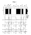
- a bar code includes alternately arranged black and white bars. Black bars B1 to B5 and white bars W1 to W4 are arranged alternately to form a bar code 1 (see (a) in Fig 1).
- the black bars B1 to B5 and the white bars W1 to W4 have widths in multiples of a basic width f0.
- the width of the black bar B1 is twice the basic width and the width of the white bar W1 is equal to the basic width.
- the width of the black bar B2 is equal to the basic width and the width of the white bar W2 is four times the basic width.
- the width of the black bar B3 is three times the basic width and the width of the white bar W3 is equal to the basic width.
- the width of the black bar B4 is equal to the basic width and the width of the white bar W4 is twice the basic width.
- a thick black bar is developed due to blurring or spreading of ink during printing and the widths of black bars B1 to B5 have increased as compared to the desired widths.
- thick portions B1a and B1b are developed on both sides of the bar. Similar thick portions are developed in the bars B2 to B5 and the amount of extra thickness in all bars is equal.
- a waveform 2 of the optical power of the reflected light includes the extra thickness of the black bars (see (b) in Fig. 1).
- a low signal is generated when the laser beam irradiates the black bars and a high signal is generated when the laser beam irradiates the white bars.
- the width of a low signal increases and the width of a high signal decreases.
- boundaries n1 to n5 from the white bars to the black bars and boundaries p1 to p4 from the black bars to the white bars are detected by differentiating waveform 2 of the optical power of the reflected light, the boundaries n1 to n5 occur earlier than when there is no thickening of the black bars and the boundaries p1 to p4 occur later than when there is no thickening of the black bars (see (c) in Fig. 1).
- the basic width of the bar code cannot be calculated accurately. Moreover, even if the width of the bar code is calculated, when amplitude of a differential waveform is acquired based on the basic width, the amplitude of the shifted position is acquired as the amplitude of the peak of the differential waveform. In other words, there is an error in reading the amplitude of the peak.
- the basic width of the bar code is calculated upon dividing the differentiation information into a positive waveform that takes a positive value and a negative waveform that takes a negative value and the respective amplitudes at the peak time are calculated from the positive waveform and the negative waveform.
- the extra width of the thick black bars is constant for all black bars. Therefore, when the positive side of the differentiation information is targeted, the boundaries p1 to p4 that indicate boundaries from the black bars to the white bars, are shifted in the same direction by the same amount (see (c) in Fig 1). Therefore, the distance between each of the boundaries p1 to p4 is a multiple of the basic width even in the case of a thick black bar.
- the boundaries n1 to n5 that indicate boundaries from the white bars to the black bars are shifted in the same direction by the same amount. Therefore, the distance between each of the boundaries n1 to n5 is a multiple of the basic width even in the case of a thick black bar.
- the basic width can be calculated accurately.
- the peak of the amplitude can be captured accurately using the basic width.
- the thick black bar is attributed to a start-up timing of amplitude acquisition rather than to the shift in the basic width.
- a configuration of a bar-code reader according to an embodiment of the present invention is described with reference to Fig. 2.
- timing signals are generated separately for the positive differential waveform and the negative differential waveform respectively and the amplitudes of the positive differential waveform and the negative differential waveform are acquired based on the respective timing signals. Then, the amplitudes of the positive differential signal and the negative differential signal are synthesized.
- the bar-code reader includes an optical scanner 11, an analog processor 12, and a digital processor 13.
- the optical scanner 11 includes a laser diode 11a and a polygon mirror 11b. A laser beam emitted from the laser diode 11a is irradiated onto the bar code 1.
- the bar code 1 is scanned by changing the position (angle) of irradiation of the laser beam by rotating the polygon mirror 11b.
- the analog processor 12 includes an optical receiver 12a, an amplifier 12b, and an AD converter 12c.
- the optical receiver 12a is realized by an optoelectric transfer element like a photodiode and outputs an optical power of the laser beam that is reflected from the bar code 1.
- the amplifier 12b amplifies the optical power of the reflected light and the AD converter 12c converts it to a digital signal.
- the digital signal is input to the digital processor 13.
- the digital processor 13 includes an extractor 21, a band-limiting differential processor 22, a sign-dividing processor 23, a positive amplitude extractor 24, a negative amplitude extractor 25, a sign synthesizer 26, a width-number counter 27, and a character composer 28.
- the extractor 21 extracts a part corresponding to the bar code from the digital signal and transmits it to the band-limiting differential processor 22. In other words, in this extraction process, an area corresponding to the bar code that has high amplitude and frequency is extracted from the digital signal.
- the band-limiting differential processor 22 calculates the basic width of the bar code from the output of the extractor 21 and performs differentiation of the optical power of the reflected light in a band of frequency that is less than the frequency of the basic width.
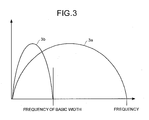
- Fig. 3 is an illustration of band-limiting differentiation.
- the frequency suitable to (for measuring) the basic width can be a frequency in a wide range from low frequency to high frequency, due to scaling, reading position, and inclination of the bar code. Therefore, to perform differentiation corresponding to all frequencies of the optical power of the reflected light, a wide bandwidth as illustrated in Fig. 3 is necessary.
- the width of black bars and white bars is the useful information.
- the width of black bars and white bars is in multiples of the basic width. Therefore, the required information is indicated (detected) by frequency that is less than the frequency of the basic width. Thus, frequencies greater than that of the basic width can be assumed to be noise that is unnecessary for reading of the bar code.
- the frequency information is acquired by eliminating the area having high frequency. This helps to improve the S/N ratio (signal to noise ratio) and to reduce the processing load of the differentiation process.
- a basic-width calculation unit 31 differentiates the extracted optical power of the reflected light and divides it into a positive and a negative (sign division unit 33).
- the frequency of the basic width is calculated from the positive differential waveform and the negative differential waveform by an FFT unit (fast Fourier transform) 34. Irrespective of presence or absence of a thick black bar, the positive differential waveform and the negative differential waveform are separated by a distance that is in multiples of the basic width. Therefore, the bandwidth can be calculated from the frequency element obtained by the FFT 34.
- the positive differential waveform and the negative differential waveform are separated by more than twice the basic width. Therefore, out of the frequency elements obtained by the FFT 34, the frequency of an element having the highest frequency becomes the frequency of the basic width. So, the basic width can be calculated by detecting an element that has the highest frequency from the calculation by FFT 34 and assuming the frequency of this element as the frequency of the basic width.
- the band-limiting differential processor 22 performs band-limiting differentiation of the optical power of the reflected light.
- the band-limiting differentiation unit 32 is able to generate a differential waveform 4 as illustrated in Fig. 4B from an optical power 2a of the reflected light that is illustrated in Fig. 4A.
- the optical power 2a of the reflected light corresponds to an array of the bar code.
- the optical power 2a of the reflected light has areas (peaks) of high optical power that correspond to the white bars and areas (regions) of low optical power that correspond to the black bars.
- the differential waveform 4 takes a positive value when the optical power 2a of the reflected light shifts from a low area to a high area and a negative value when the optical power 2a of the reflected light shifts from a high area to a low area.
- the band-limiting differential processor 22 outputs the differential waveform 4 to the sign-dividing processor 23.
- the sign-dividing processor 23 divides the differential waveform 4 into a positive value and a negative value and forms a positive differential waveform 5a and a negative differential waveform 5b.
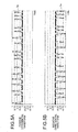
- Fig. 5A is an illustration of the positive differential waveform 5a that is formed from the differential waveform 4. As illustrated in this diagram, when the amplitude of the differential waveform 4 is a positive value, the positive differential waveform 5a adopts this positive value and when the amplitude of the differential waveform 4 is a negative value, the amplitude in the positive differential waveform 5a is assumed to be '0'.
- Fig. 5B is an illustration of the negative waveform 5b that is formed from the differential waveform 4.
- the sign-dividing processor 23 transmits the positive differential waveform 5a to the positive amplitude extractor 24 and the negative differential waveform 5b to the negative amplitude extractor 25.
- the positive amplitude extractor 24 uses the basic width calculated by the band-limiting differential processor 22, to ternarize (select a ternary value for) the positive differential waveform 5a. Concretely, the positive amplitude extractor 24 extracts a timing signal with a timing-signal extraction unit 41, performs amplitude extraction, with an amplitude extraction unit 42, of the positive differential waveform 5a based on the timing signal, and then performs a ternarization of (ternarizes) the amplitude extraction result using a ternarization unit 43.
- the timing signal extracted is a signal that specifies the timing of acquiring the amplitude from the positive differential waveform 5a.
- a thick black bar is developed (present) in the bar code 1.
- the positive differential waveform 5a includes only a peak indicating a boundary from a black bar to a white bar. As the boundary from a black bar to a white bar is shifted in the same direction, all peaks can be acquired accurately by acquiring the amplitude of the positive differential waveform 5a based on the timing signal of the basic width interval.
- the timing signal extraction unit 41 detects a first peak of the positive differential waveform 5a and with the first peak as a base point, extracts the timing signal of the basic width interval.
- the basic width calculated by the band-limiting differential processor 22 is used as the basic width.
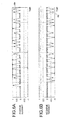
- the amplitude extraction unit 42 acquires the amplitude of the positive differential waveform 5a based on the timing signal extracted by the timing signal extraction unit 41. Moreover, the ternarization unit 43 assigns to the amplitude acquired by the amplitude extraction unit any one of values 1, 0, and -1. The result of the ternarization is illustrated in Fig. 6A.
- the value 1 in the ternarization denotes the boundary from a black bar to a white bar and the value 0 denotes continuation of a black bar or a white bar. Moreover, the value -1 in the ternarization denotes the boundary from a white bar to a black bar. However, since the positive differential waveform 5a does not include amplitudes less than zero, the value of -1 does not appear and only the value 1 or 0 appears in the positive ternary signal 6a.
- the negative amplitude extractor 25 uses the basic width calculated by the band-limiting differential processor 22, to ternarize (select a ternary value for) the negative differential waveform 5b. Concretely, the negative amplitude extractor 25 extracts a timing signal with a timing-signal extraction unit 44, performs an amplitude extraction, using an amplitude extraction unit 45, of the negative differential waveform 5b based on the timing signal, and then performs a ternarization of the amplitude extraction result using a ternarization unit 46.
- the timing signal extracted is a signal that specifies the timing of acquiring the amplitude from the negative differential waveform 5b.
- the negative differential waveform 5b includes only a peak indicating a boundary from a white bar to a black bar. As the boundary from a white bar to a black bar is shifted in the same direction, all peaks can be acquired accurately by acquiring the amplitude of the negative differential waveform 5b based on the timing signal of the basic width interval.
- the timing-signal extraction unit 44 detects a first peak of the negative differential waveform 5b and with the first peak as a base point, extracts the timing signal of the basic width interval.
- the basic width calculated by the band-limiting differential processor 22 is used as the basic width.
- the amplitude extraction unit 45 acquires the amplitude of the negative differential waveform 5b based on the timing signal extracted by the timing signal extraction unit 44. Moreover, the ternarization unit 46 assigns to the amplitude acquired by the amplitude extraction unit any one of values 1, 0, and -1. The result of the ternarization is illustrated in Fig. 6B.
- the negative differential waveform 5b does not include amplitudes greater than zero, the value 1 does not appear and only the value 0 or -1 appears in the negative ternary signal 6b.
- the sign synthesizer 26 forms a synthesized ternary signal by synthesizing the positive ternary signal 6a and the negative ternary signal 6b and outputs it to the width-number counter 27.
- the signals 6a and 6b are synthesized such that the distance between a peak of the positive ternary signal 6a and a peak of the negative ternary signal 6b is an integral multiple of the basic width. This helps to achieve a synthesized ternary signal for a corrected thick black bar in the bar code 1.
- the positive ternary signal 6a and the negative ternary signal 6b both undergo sampling in the basic width. Therefore, synthesizing is performed by synchronized sampling timings. This enables the distance between the peak of the positive ternary signal 6a and the peak of the negative ternary signal 6b, to be made an integral multiple of the basic width.
- the first sampling timing of the positive ternary signal 6a and the first sampling timing of the negative ternary signal 6b may be synchronized. However, there may be a sampling dropout in the positive ternary signal 6a and the negative ternary signal 6b.
- the synthesis is carried out by shifting the sampling timing that is a base point of the positive ternary signal 6a and the sampling timing that is a base point of the negative ternary signal 6b.
- a plurality of synthesized ternary signals having different base points is formed.
- the sampling timing of the synthesized ternary signal is k (1 ⁇ k ⁇ n)
- the value in the sampling timing of the synthesized ternary signal k is S(k)
- the Energy E of the synthesized ternary signal is calculated as:
- the energy E may be calculated for a plurality of synthesized ternary signals and compared.
- Fig. 7A illustrates a synthesized ternary signal 7a that is synthesized by synchronizing the first sampling timing of the positive ternary signal 6a and the first sampling timing of the negative ternary signal 6b.
- Fig. 7B illustrates a synthesized ternary signal 7b that is synthesized by synchronizing a first sampling timing of the positive ternary signal 6a and a second sampling timing of the negative ternary signal 6b.
- Fig. 7C illustrates a synthesized ternary signat 7c that is synthesized by synchronizing the second sampling timing of the positive ternary signal 6a and the first sampling timing of the negative ternary signal 6b.
- a peak suppression 8a in the synthesized ternary signal 7a and a peak suppression 8b in the synthesized ternary signal 7c Due to this, when the energies of the synthesized ternary signal 7a, 7b, and 7c are compared, the energy of the synthesized ternary signal 7b is maximum. Therefore, the sign synthesizer 26 outputs the synthesized ternary signal 7b to the width-number counter 27.
- the synchronized control of the sampling timing need not be necessarily performed by this method. Any method that can carry out the synchronized control such that the energy of the synthesized ternary signal becomes maximum can be used. For example, an ideal value of energy of a synthesized ternary signal can be obtained by calculating the energy of the positive ternary signal 6a and the negative ternary signal 6b and then adding them.
- the synchronized control of the sampling timings may be carried out either to match the value of the synthesized ternary signal with the ideal value of energy of the synthesized ternary signal or to bring the value of the synthesized ternary signal closest to the ideal value of energy of the synthesized ternary signal.
- the width-number counter 27 reproduces the bar code from the synthesized ternary signal output by the sign synthesizer 26. Concretely, the area (value) from the value -1 to 1 of the synthesized ternary signal is detected as a black bar and the area (value) from the value 1 to -1 is detected as a white bar. The width number is calculated in terms of multiples of the basic width of the black bar and white bar that are detected and an array of the bar code 1 is reproduced. The thick black bar in the bar code 1 that is reproduced is corrected. The corrected bar-code data is transmitted to the character composer 28.
- the character composer 28 converts the corrected bar-code data to character data that is an array of numerals and letters and transmits it to an external unit like a POS (point of sales) terminal.
- the optical power of the reflected light is differentiated and then divided into a positive differential waveform and a negative differential waveform.
- the amplitudes of the positive differential waveform and the negative differential waveform are acquired based on the respective timing signals, and then synthesized. This enables to read the bar code accurately by correcting the thickening and thinning of the bar code.
- the timing signal to acquire the amplitude from the positive differential signal and the timing signal to acquire the amplitude from the negative differential signal are extracted separately.
- the amplitude from the negative differential signal is acquired by using the timing signal obtained by delaying the timing signal corresponding to the positive differential signal by a predetermined amount of time.
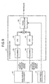
- Fig. 8 is a bar-code reader according to the second embodiment of the present invention.
- the bar-code reader illustrated in Fig. 8 includes a thickness extractor 51 that extracts the thickness of a black bar in the bar code from the positive differential signal and the negative differential signal output by the sign-dividing processor 23.
- the negative amplitude extractor 25a causes a delay in the timing signal extracted by the positive amplitude extractor 24, based on the thickness and acquires the amplitude of the negative differential signal.
- the thickness extractor 51 concretely, extracts thickness from the correlation between the positive differential wavelength and the negative differential wavelength.
- Fig. 9 is an illustration of a process executed by the thickness extractor 51. As shown in Fig. 9, the thickness extractor 51 performs squaring, in a squaring unit 52, of the positive differential signal output by the sign-dividing processor 23 and then the squared signal is transformed in an FFT 53. Similarly, the thickness extractor 51 performs squaring, in a squaring unit 54, of the negative differential signal output by the sign-dividing processor 23 and then the squared signal is transformed in an FFT 55.
- the squaring of the signals is not essential and the positive differential waveform and the negative differential waveform may be transformed directly in the FFT 53 and in the FFT 55 respectively.
- phase calculation unit 56 uses the basic width calculated by the basic-width calculation unit 31.
- the phase difference obtained by the phase calculation unit 56 is a phase difference between the positive differential waveform and the negative differential waveform, i.e. an excessive thickness of the black bar.
- the timing signal corresponding to the positive differential waveform is delayed by an amount of the phase difference calculated by the phase calculator 56. This enables a timing signal corresponding to the negative differential signal to be obtained.
- the thickness extraction need not be necessarily done by calculating the phase difference. Any method that is able to accurately calculate the excessive thickness of the black bar can be employed. For example, widths of black bars B1 to B4 and widths of white bars W1 to W4 can be compared with the basic width and the excessive thickness may be calculated from the comparison results.
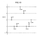
- Fig. 10 is an illustration of a concept of thickness extraction by comparison with the basic width. Due to the thickness of a black bar in the bar code 1, (see Fig. 1) the width of the black bars B1 to B4 becomes greater than the original width and the width of the white bars W1 to W4 becomes smaller than the original width. As illustrated in Fig. 10, the original width of the black bar B1 is twice the basic width (width number 2), however the width number of the black bar B1 in the bar code 1 becomes greater by the amount of excessive thickness.
- the original width of black bars B2, B3, and B4 are respectively equal to (width number 1), three times (width number 3), and equal to (width number 1) the basic width, however the width numbers of the black bars B2, B3, and B4 in the bar code 1 become greater by the respective amount of excessive thickness.
- the original width of the white bar is equal to the basic width (width number 1), but the width number of the white bar W1 in the bar code 1 becomes smaller by the amount of excessive thickness of the black bar.
- the original widths of the white bars W2, W3, and W4 are respectively four times (width number 4), equal to (width number 1), and twice (width number 2) the basic width, however the width numbers of the white bars W2, W3, and W4 in the bar code 1 become smaller by the respective amount of the excessive thickness of the black bar.
- the amount of increase in the width numbers of the bars B1 to B4 is equal to the amount of decrease in the width numbers of the bars W1 to W4. Therefore, the excessive thickness can be calculated by dividing each width number by the basic width.
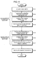
- the thickness extractor 51 acquires a basic width f0 calculated by the basic-width calculation unit 31 (step S101).
- the thickness extractor 51 calculates an average thickness Mav from MBav and MWav (step S108). Concretely, the thickness extractor 51 compares the deviation of each element of ⁇ MB' and the deviation of each element of ⁇ MW' and selects the lesser of the two as average thickness Mav.
- ⁇ MB' and ⁇ MW' are formed by elements having values in the range of 0 to 2.0, it is classified into either 'a group of those thickened from 1 mod' or 'a group of those thinned from 1 mod and those thinned from 2 mod'.
- the deviation of elements in the 'group of those thickened from 1 mod' is less than the deviation of elements in the 'group of those thinned from 1 mod and those thinned from 2 mod'. Therefore, an average value of elements in the group for which the deviation is smaller is taken. This enables to obtain an average value of the group of those thickened from 1 mod' and to calculate the thickening of 1 mod.
- the thickness extractor 51 transmits Mav as a thickness, to the negative amplitude extractor 25a.
- the negative amplitude extractor 25a acquires the amplitude of the negative differential signal by a timing signal obtained by delaying by Mav, the timing signal corresponding to the positive differential signal.
- the thickness of the bar code is calculated from the positive differential signal and the negative differential signal.
- the amplitude of the positive differential signal is acquired by extracting the timing signal corresponding to the positive differential signal and the amplitude of the negative differential signal is acquired by using the timing signal that is obtained by delaying the timing signal corresponding to the positive differential signal according to the thickness.
- the amplitudes of the positive differential signal and the negative differential signal are synthesized. This enables to perform correction of thickening and thinning of the bar code and to read the bar code accurately.
- the timing signal used in amplitude extraction of the negative differential signal is generated from the timing signal corresponding to the positive differential signal.
- the timing signal corresponding to the negative differential side may be generated beforehand and the timing signal that is used in the amplitude extraction of the positive differential signal may be generated by delaying the timing signal that is generated beforehand.
- the synthesis is performed after acquiring the amplitudes, based on the respective timings from the positive differential signal and the negative differential signal.
- the thickness is extracted from the positive differential signal and the negative differential signal, and after performing the synthesis of the positive differential signal and the negative differential signal based on the thickness, the amplitude is acquired from the synthesized differential signal.
- Fig. 12 is a bar-code reader according to the third embodiment of the present invention.
- the bar-code reader illustrated in Fig. 12 includes a delay unit 61, a sign synthesizer 62, and an amplitude extractor 63. Since the rest of the configuration and operation are similar to the bar-code reader in the second embodiment, the same reference numerals are used for the identical components and the description is omitted.
- the delay unit 61 causes a delay in the negative differential waveform based on the thickness extracted by the thickness extractor 51.
- the sign synthesizer 62 synthesizes the positive differential waveform output by the sign-dividing processor 23 and the negative differential waveform output by the delay unit 61.
- the synthesized differential waveform that is formed by the sign synthesizer 62 is a differential waveform that is subjected to thickness correction of the bar code 1 and the distance between a peak on the positive side of the differential waveform and a peak on the negative side of the differential waveform is an integral multiple of the basic width.
- the amplitude extractor 63 performs the extraction of the amplitude of the synthesized differential waveform using a single timing signal. This permits acquisition of both the peak of the positive amplitude and the peak of the negative amplitude, accurately.
- the amplitude extractor 63 using the basic width calculated by the basic-width calculation 31, ternarizes (selects a ternary value for) the synthesized differential waveform generated by the sign synthesizer 62. More concretely, the amplitude extractor 63 extracts the timing signal by a timing-signal extraction, using a timing-signal extraction unit 66, executes an amplitude extraction, using as an amplitude extraction unit 64, of the synthesized differential waveform based on the timing signal extracted, and performs a ternarization of the result of the amplitude extraction using a ternarization unit 65.
- the timing-signal extraction unit 66 detects the first peak of the synthesized differential waveform and extracts a timing signal that has a basic width interval with the first peak as a base point.
- the basic width calculated by the band-limiting differential processor 22 is used as the basic width in this case.
- the amplitude extraction unit 64 acquires the amplitude of the synthesized differential waveform based on the timing signal extracted by the timing extraction unit 66. Moreover, the ternarization unit 65 assigns to the amplitude acquired by the amplitude extraction 64 any one of the values '1, 0, and -1' and outputs a synthesized ternary signal.
- the thickness is calculated based on the positive differential waveform and the negative differential waveform.
- the negative differential waveform is delayed based on the thickness.
- the synthesized differential waveform is formed by synthesizing the positive differential waveform and the negative differential waveform. This enables to achieve a synthesized differential waveform that is subjected to the correction of the thickening and thinning of the bar code and to read the bar code accurately.
- the negative differential waveform is delayed and synthesized with the positive differential waveform.
- the positive differential waveform may be delayed and synthesized with the negative differential waveform.
- first, the second, and the third embodiments are described with reference to an example of the thick black bar that has an increased width as compared to the original width of the black bar. It is needless to mention that a correction can be carried out by an identical process in a case of a thin black bar that has a decreased width as compared to the original width of the black bar.
- the FFT 34 calculates the basic width from the positive differential waveform and the negative differential waveform.
- the method for calculating the basic width need not be necessarily restricted to that employing the FFT.
- the basic width may be calculated by employing any method that does not depend on the thickening and the thinning of the bar code.
- a computer program may realize the method of reading the bar code.
- the computer program may be stored in a computer-readable medium such as a ROM and a CPU may execute the program.
- a differential waveform of an optical power of reflected light is formed by a differentiating unit, and is divided into a positive waveform and a negative waveform.
- Corrected bar-code data in which correct width of black bars of the bar code is computed using the positive waveform and the negative waveform, is generated.
- the corrected bar-code data is converted into character data that is an array of numerals and letters.
- amplitude information of the positive waveform is acquired using a timing signal that is generated corresponding to the positive waveform.
- Amplitude information of the negative waveform is acquired using a timing signal that is generated corresponding to the negative waveform.
- Corrected bar-code data generated by synthesizing the amplitude information of the positive waveform and the amplitude information of the negative waveform.
- amplitude information of the positive waveform is acquired by generating a timing signal corresponding to the positive waveform.
- Amplitude information of the negative waveform is acquired using a timing signal in which the timing signal corresponding to the positive waveform is delayed by a predetermined amount.
- the corrected bar-code data is generated by synthesizing the amplitude information of the positive waveform and the amplitude information of the negative waveform.
- a synthesized waveform is generated by synthesizing the positive waveform with the negative waveform that is delayed by a predetermined amount. Amplitude information acquired from the synthesized waveform using a predetermined timing signal is used as corrected bar-code data.
- a differential waveform of an optical power of reflected light that is formed at a differentiating step is divided into a positive waveform and a negative waveform.
- Corrected bar-code data in which correct width of bar code is computed from the positive waveform and the negative waveform, is created.
- the corrected bar-code data is converted into an alphanumeric data string (array).
- the present invention provides a bar-code reader and a method of reading a bar code that enables an accurate reading of a bar code by correcting a thickening and a thinning of the bar code.
- Black bars” and “white bars” of a bar code referred to herein are not limited solely to being black and white.
- Black bars may include any less reflective areas such as dark bars, coloured bars or printed bars.
- White bars may include any more reflective areas such as light bars or coloured bars.
Landscapes
- Physics & Mathematics (AREA)
- Engineering & Computer Science (AREA)
- Electromagnetism (AREA)
- Artificial Intelligence (AREA)
- Toxicology (AREA)
- General Health & Medical Sciences (AREA)
- Health & Medical Sciences (AREA)
- Computer Vision & Pattern Recognition (AREA)
- General Physics & Mathematics (AREA)
- Theoretical Computer Science (AREA)
- Character Discrimination (AREA)
- Character Input (AREA)
- Length Measuring Devices By Optical Means (AREA)
Applications Claiming Priority (2)
| Application Number | Priority Date | Filing Date | Title |
|---|---|---|---|
| JP2003045082 | 2003-02-21 | ||
| JP2003045082A JP4257132B2 (ja) | 2003-02-21 | 2003-02-21 | バーコード読取装置およびバーコード読取方法 |
Publications (3)
| Publication Number | Publication Date |
|---|---|
| EP1450293A2 true EP1450293A2 (de) | 2004-08-25 |
| EP1450293A3 EP1450293A3 (de) | 2004-11-10 |
| EP1450293B1 EP1450293B1 (de) | 2009-04-01 |
Family
ID=32733012
Family Applications (1)
| Application Number | Title | Priority Date | Filing Date |
|---|---|---|---|
| EP04250497A Expired - Lifetime EP1450293B1 (de) | 2003-02-21 | 2004-01-29 | Strichcode-Leser, Methode zum Lesen eines Strichcodes und Computerprodukt |
Country Status (4)
| Country | Link |
|---|---|
| US (1) | US7021545B2 (de) |
| EP (1) | EP1450293B1 (de) |
| JP (1) | JP4257132B2 (de) |
| DE (1) | DE602004020288D1 (de) |
Families Citing this family (10)
| Publication number | Priority date | Publication date | Assignee | Title |
|---|---|---|---|---|
| KR100715754B1 (ko) * | 2001-01-26 | 2007-05-08 | 후지쯔 가부시끼가이샤 | 정보 판독 방법 및 장치 |
| ATE469071T1 (de) * | 2004-09-28 | 2010-06-15 | Laitram Llc | Vorrichtung und verfahren zum hochgeschwindigkeitsschalten von fördereinrichtungen |
| US8196836B2 (en) * | 2007-06-28 | 2012-06-12 | Fuji Xerox Co., Ltd. | Image processing apparatus, image processing method and computer-readable medium |
| JP4539701B2 (ja) | 2007-09-26 | 2010-09-08 | 富士ゼロックス株式会社 | コード読取装置、及びコード読取プログラム |
| JP5398653B2 (ja) * | 2010-06-30 | 2014-01-29 | 株式会社オプトエレクトロニクス | デコード方法及びデコード処理装置 |
| US8333326B2 (en) * | 2010-10-07 | 2012-12-18 | Nidec Sankyo Corporation | Stacked barcode reader and stacked barcode reading method |
| JP5293853B1 (ja) * | 2012-03-28 | 2013-09-18 | 株式会社デンソーウェーブ | バーコード読取装置 |
| US10146978B2 (en) * | 2015-07-14 | 2018-12-04 | Afero, Inc. | Apparatus and method for accurate barcode scanning using dynamic timing feedback |
| US9626543B1 (en) * | 2015-12-14 | 2017-04-18 | Afero, Inc. | Apparatus and method for accurate barcode scanning using dynamic timing feedback |
| JP2021103499A (ja) * | 2019-12-26 | 2021-07-15 | セイコーエプソン株式会社 | 画像処理装置、印刷装置および画像処理方法 |
Family Cites Families (7)
| Publication number | Priority date | Publication date | Assignee | Title |
|---|---|---|---|---|
| JPS55143682A (en) | 1979-04-24 | 1980-11-10 | Fujitsu Ltd | Read system for bar code information |
| JPH07225806A (ja) | 1994-02-10 | 1995-08-22 | Tec Corp | 2次元コードリーダ |
| JPH10162095A (ja) | 1996-11-29 | 1998-06-19 | Fujitsu Ltd | スライスレシオ制御回路 |
| JP3510496B2 (ja) * | 1998-09-28 | 2004-03-29 | 富士通株式会社 | バー幅補正装置,バー幅補正方法,バーコード読取装置及びそのバーコード復調方法 |
| JP4117368B2 (ja) | 1999-06-14 | 2008-07-16 | 富士通株式会社 | バーコード読取装置及びバーコード読取方法 |
| JP2001019271A (ja) | 1999-07-01 | 2001-01-23 | Ricoh Co Ltd | 画像形成複合装置 |
| DE60118051T2 (de) * | 2000-04-06 | 2006-08-31 | Seiko Epson Corp. | Verfahren und Vorrichtung zum Lesen von einem zwei-dimensionalen Strichkode und Datenspeichermedium |
-
2003
- 2003-02-21 JP JP2003045082A patent/JP4257132B2/ja not_active Expired - Fee Related
-
2004
- 2004-01-26 US US10/763,338 patent/US7021545B2/en not_active Expired - Lifetime
- 2004-01-29 EP EP04250497A patent/EP1450293B1/de not_active Expired - Lifetime
- 2004-01-29 DE DE602004020288T patent/DE602004020288D1/de not_active Expired - Lifetime
Also Published As
| Publication number | Publication date |
|---|---|
| EP1450293B1 (de) | 2009-04-01 |
| JP2004252905A (ja) | 2004-09-09 |
| US7021545B2 (en) | 2006-04-04 |
| JP4257132B2 (ja) | 2009-04-22 |
| EP1450293A3 (de) | 2004-11-10 |
| DE602004020288D1 (de) | 2009-05-14 |
| US20040164161A1 (en) | 2004-08-26 |
Similar Documents
| Publication | Publication Date | Title |
|---|---|---|
| EP1450293B1 (de) | Strichcode-Leser, Methode zum Lesen eines Strichcodes und Computerprodukt | |
| US20220113422A1 (en) | Lidar system and method of operation | |
| CN114096880A (zh) | Lidar系统中的波长选择 | |
| JP2001522103A (ja) | 電子エッジ検出装置 | |
| US11402476B2 (en) | Method and apparatus for LIDAR channel encoding | |
| US5012089A (en) | Scanning beam control system and optical scale structure useful thereto | |
| EP1174721A2 (de) | Jitterdetektionsvorrichtung und Phasenregelschleife unter Verwendung des erfassten Jitters | |
| JPH1091714A (ja) | 信号からキャラクタ情報を決定するための方法およびバーコードラベルを読み取るためのシステム | |
| US7007847B2 (en) | Bar-code reader and method of reading bar-code | |
| US6193157B1 (en) | Frequency division multiplexed bar code scanner | |
| WO2022124066A1 (ja) | 測距装置、および測距方法、並びにプログラム | |
| US5777311A (en) | Optoelectronic a device employing a digital filter which operates in different coefficient sets | |
| JPH10173604A (ja) | 周波数変調装置 | |
| EP0921492B1 (de) | Verfahren zur Kompensation der Flankenposition durch Abtastung eines Strichcodes generierten Signals | |
| KR20050057473A (ko) | 스캐닝하는 동안의 자동 이득 제어를 위한 장치 및 방법 | |
| JP4136796B2 (ja) | 周波数変調装置 | |
| JP7211212B2 (ja) | 測距モジュール | |
| US20070212077A1 (en) | Ultra Wideband Communication System, Transmission Device Reception Device, and Replay Device Used for the Same | |
| CA2219873C (en) | A bar code reader | |
| JP3500263B2 (ja) | マルチビーム画像形成装置 | |
| JP2790736B2 (ja) | 半導体レーザ光源装置およびバーコード読取装置 | |
| JPH04292068A (ja) | 画像記録装置 | |
| US7055748B2 (en) | Barcode reader, method and program for reading barcode, and module-point extracting apparatus | |
| KR100300643B1 (ko) | 광메모리카드의트랙킹제어방법및장치 | |
| JP2749889B2 (ja) | 多点同期光書込み装置 |
Legal Events
| Date | Code | Title | Description |
|---|---|---|---|
| PUAI | Public reference made under article 153(3) epc to a published international application that has entered the european phase |
Free format text: ORIGINAL CODE: 0009012 |
|
| AK | Designated contracting states |
Kind code of ref document: A2 Designated state(s): AT BE BG CH CY CZ DE DK EE ES FI FR GB GR HU IE IT LI LU MC NL PT RO SE SI SK TR |
|
| AX | Request for extension of the european patent |
Extension state: AL LT LV MK |
|
| PUAL | Search report despatched |
Free format text: ORIGINAL CODE: 0009013 |
|
| AK | Designated contracting states |
Kind code of ref document: A3 Designated state(s): AT BE BG CH CY CZ DE DK EE ES FI FR GB GR HU IE IT LI LU MC NL PT RO SE SI SK TR |
|
| AX | Request for extension of the european patent |
Extension state: AL LT LV MK |
|
| 17P | Request for examination filed |
Effective date: 20050504 |
|
| AKX | Designation fees paid |
Designated state(s): DE FR GB |
|
| 17Q | First examination report despatched |
Effective date: 20070713 |
|
| GRAP | Despatch of communication of intention to grant a patent |
Free format text: ORIGINAL CODE: EPIDOSNIGR1 |
|
| GRAS | Grant fee paid |
Free format text: ORIGINAL CODE: EPIDOSNIGR3 |
|
| GRAA | (expected) grant |
Free format text: ORIGINAL CODE: 0009210 |
|
| AK | Designated contracting states |
Kind code of ref document: B1 Designated state(s): DE FR GB |
|
| REG | Reference to a national code |
Ref country code: GB Ref legal event code: FG4D |
|
| REF | Corresponds to: |
Ref document number: 602004020288 Country of ref document: DE Date of ref document: 20090514 Kind code of ref document: P |
|
| PLBE | No opposition filed within time limit |
Free format text: ORIGINAL CODE: 0009261 |
|
| STAA | Information on the status of an ep patent application or granted ep patent |
Free format text: STATUS: NO OPPOSITION FILED WITHIN TIME LIMIT |
|
| 26N | No opposition filed |
Effective date: 20100105 |
|
| PGFP | Annual fee paid to national office [announced via postgrant information from national office to epo] |
Ref country code: FR Payment date: 20091221 Year of fee payment: 7 |
|
| PGFP | Annual fee paid to national office [announced via postgrant information from national office to epo] |
Ref country code: GB Payment date: 20100128 Year of fee payment: 7 Ref country code: DE Payment date: 20100212 Year of fee payment: 7 |
|
| GBPC | Gb: european patent ceased through non-payment of renewal fee |
Effective date: 20110129 |
|
| REG | Reference to a national code |
Ref country code: FR Ref legal event code: ST Effective date: 20110930 |
|
| PG25 | Lapsed in a contracting state [announced via postgrant information from national office to epo] |
Ref country code: FR Free format text: LAPSE BECAUSE OF NON-PAYMENT OF DUE FEES Effective date: 20110131 |
|
| PG25 | Lapsed in a contracting state [announced via postgrant information from national office to epo] |
Ref country code: GB Free format text: LAPSE BECAUSE OF NON-PAYMENT OF DUE FEES Effective date: 20110129 |
|
| REG | Reference to a national code |
Ref country code: DE Ref legal event code: R119 Ref document number: 602004020288 Country of ref document: DE Effective date: 20110802 |
|
| PG25 | Lapsed in a contracting state [announced via postgrant information from national office to epo] |
Ref country code: DE Free format text: LAPSE BECAUSE OF NON-PAYMENT OF DUE FEES Effective date: 20110802 |