EP1450010A2 - Actionneur électromécanique de soupape pour moteur à combustion interne et moteur à combustion interne muni d'un tel actionneur - Google Patents
Actionneur électromécanique de soupape pour moteur à combustion interne et moteur à combustion interne muni d'un tel actionneur Download PDFInfo
- Publication number
- EP1450010A2 EP1450010A2 EP04300048A EP04300048A EP1450010A2 EP 1450010 A2 EP1450010 A2 EP 1450010A2 EP 04300048 A EP04300048 A EP 04300048A EP 04300048 A EP04300048 A EP 04300048A EP 1450010 A2 EP1450010 A2 EP 1450010A2
- Authority
- EP
- European Patent Office
- Prior art keywords
- electromagnet
- plate
- actuator
- stop
- internal combustion
- Prior art date
- Legal status (The legal status is an assumption and is not a legal conclusion. Google has not performed a legal analysis and makes no representation as to the accuracy of the status listed.)
- Granted
Links
- 238000002485 combustion reaction Methods 0.000 title claims abstract description 9
- 239000011668 ascorbic acid Substances 0.000 description 3
- 239000000463 material Substances 0.000 description 3
- 238000010586 diagram Methods 0.000 description 2
- 229920001971 elastomer Polymers 0.000 description 2
- 239000000806 elastomer Substances 0.000 description 2
- 238000006073 displacement reaction Methods 0.000 description 1
- 230000005611 electricity Effects 0.000 description 1
- 238000002347 injection Methods 0.000 description 1
- 239000007924 injection Substances 0.000 description 1
- 239000000696 magnetic material Substances 0.000 description 1
- 210000000056 organ Anatomy 0.000 description 1
- 230000002093 peripheral effect Effects 0.000 description 1
- 230000035939 shock Effects 0.000 description 1
Images


Classifications
-
- F—MECHANICAL ENGINEERING; LIGHTING; HEATING; WEAPONS; BLASTING
- F01—MACHINES OR ENGINES IN GENERAL; ENGINE PLANTS IN GENERAL; STEAM ENGINES
- F01L—CYCLICALLY OPERATING VALVES FOR MACHINES OR ENGINES
- F01L9/00—Valve-gear or valve arrangements actuated non-mechanically
- F01L9/20—Valve-gear or valve arrangements actuated non-mechanically by electric means
-
- F—MECHANICAL ENGINEERING; LIGHTING; HEATING; WEAPONS; BLASTING
- F01—MACHINES OR ENGINES IN GENERAL; ENGINE PLANTS IN GENERAL; STEAM ENGINES
- F01L—CYCLICALLY OPERATING VALVES FOR MACHINES OR ENGINES
- F01L9/00—Valve-gear or valve arrangements actuated non-mechanically
- F01L9/20—Valve-gear or valve arrangements actuated non-mechanically by electric means
- F01L9/21—Valve-gear or valve arrangements actuated non-mechanically by electric means actuated by solenoids
- F01L2009/2132—Biasing means
- F01L2009/2134—Helical springs
- F01L2009/2136—Two opposed springs for intermediate resting position of the armature
-
- F—MECHANICAL ENGINEERING; LIGHTING; HEATING; WEAPONS; BLASTING
- F01—MACHINES OR ENGINES IN GENERAL; ENGINE PLANTS IN GENERAL; STEAM ENGINES
- F01L—CYCLICALLY OPERATING VALVES FOR MACHINES OR ENGINES
- F01L9/00—Valve-gear or valve arrangements actuated non-mechanically
- F01L9/20—Valve-gear or valve arrangements actuated non-mechanically by electric means
- F01L9/21—Valve-gear or valve arrangements actuated non-mechanically by electric means actuated by solenoids
- F01L2009/2146—Latching means
- F01L2009/2148—Latching means using permanent magnet
-
- F—MECHANICAL ENGINEERING; LIGHTING; HEATING; WEAPONS; BLASTING
- F01—MACHINES OR ENGINES IN GENERAL; ENGINE PLANTS IN GENERAL; STEAM ENGINES
- F01L—CYCLICALLY OPERATING VALVES FOR MACHINES OR ENGINES
- F01L9/00—Valve-gear or valve arrangements actuated non-mechanically
- F01L9/20—Valve-gear or valve arrangements actuated non-mechanically by electric means
- F01L9/21—Valve-gear or valve arrangements actuated non-mechanically by electric means actuated by solenoids
- F01L2009/2151—Damping means
Definitions
- the present invention relates to an actuator electromechanical valve for internal combustion engine and to an internal combustion engine provided with such an actuator.
- An electromechanical actuator 100 (FIG. valve 110 comprises mechanical means, such as springs 102 and 104, and electromagnetic means, such as electromagnets 106 and 108, for controlling the position of the valve 110 by means of electrical signals.
- the tail of the valve 110 is applied against the rod 112 of a magnetic plate 114 located between the two electromagnets 106 and 108.
- valve 110 When the electromechanical actuator 100 operates correctly, the valve 110 alternates open or closed fixed, so-called switched, with displacements transients between these two positions. Subsequently, we denominate "switched state" the state of an open valve or closed.
- an actuator 150 (FIG. 1b) can be equipped with magnets 168 (electromagnet 158) and 166 (electromagnet 156) intended to reduce the energy required to maintain tray 164 in a switched position, that is to say in contact against one of the electromagnets.
- each magnet e.g., magnet 166 is located between two sub-elements 156 a and 156 b of the electromagnet 156 so that its magnetic field combines with the field created by the electromagnet.
- An electromagnet provided with a magnet is hereinafter referred to as polarized electromagnet.
- the present invention results from the observation that the contacts between a magnetic plate and an electromagnet, each time the valve is switched on, generates a noise the intensity generally increases when the contact surface between the plate and the electromagnet increases, this noise of contact representing a significant part of the noise of operation of an engine.
- the invention also results from the finding that the use of a polarized electromagnet increases the range of the action exercised by the latter on the associated plateau of such so that the control of the plate by the electromagnet can be realized with a limited power supply of the actuator despite the presence of the air gap generated by a stop.
- an actuator electromechanical valve for internal combustion engine comprising an electromagnet and a movable magnetic plate intended to come into contact with an organ of this electromagnet, at least one stop being located on the electromagnet or on the tray to limit the contact area between the tray and the electromagnet, characterized in that the electromagnet comprises a magnet in its magnetic circuit.
- the invention thus makes it possible to reduce the surface of contact between the plate and the electromagnet, and consequently the sound of engine operation, while the use of a magnet makes it possible to compensate for the air gap generated by the abutment.
- this noise gain has advantages, particularly related to passenger comfort, while the increase in electricity consumption of the electromagnet, caused by the presence of an extra air gap generated by the stop, is compensated by the presence of a magnet increasing the range of the electromagnet.
- the stop is substantially located in the center of the surface of the electromagnet.
- the stop is located on an axis collinear with the axis of translation of the plate.
- a plurality of abutments being located on the electromagnet and / or on the plate, the latter are arranged symmetrically with respect to the axis of translation of the plateau.
- the electromagnet being formed by E support with three branches, the stop is located at the end of one of the branches of the support.
- the stop when the electromagnet and the plate are in contact, the stop maintains a gap between each extreme branch of the electromagnet support and the tray.
- the magnet is located on the surface of one of the branches of the support, vis-à-vis the plateau magnetic.
- the stop is fixed between these two magnets.
- the stop is made of material magnetic.
- the stop is made of material elastic, for example of the elastomer type.
- the invention also relates to a combustion engine internal with an electromechanical valve actuator comprising an electromagnet and a movable magnetic plate coming into contact with the electromagnet.
- the actuator of such an engine is in accordance with one of embodiments of actuators described below.
- Polarized electromagnets have the advantage of exercising a action less sensitive to the variation of the gap between the magnetic platter and the electromagnet that non electromagnets polarized, as shown in FIG.
- This figure 2 is a diagram representing the strength of attraction (y-axis 200, in N / m) exerted by a active polarized electromagnet (curve 202), that is to say generating a magnetic field by means of its coil, or inactive (curve 204), and an unpolarized electromagnet (curve 206) on a magnetic plate according to the gap separating the considered electromagnet of the plateau.
- the scope of the action exercised by the polarized electromagnet (curve 202) is greater than the range of the unpolarized electromagnet. More precisely, the action exerted by the polarized electromagnet on the board Magnetic with a gap of 3 mm is equivalent to the action exerted by the unpolarized electromagnet with a gap of 1.7 mm.
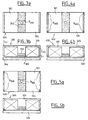
- Figures 3a and 3b show a first embodiment of an electromechanical actuator 300, according to according to a top view (FIG. 3a) or a view of side ( Figure 3b).
- a single abutment B 300 intended to maintain a gap between the support 304 of the electromagnet 301 and the plate 306, is disposed on the support 304 between two magnets 302 disposed on the same surface.
- the end branches E 300 of the support 304 are limited so as to maintain an air gap e between the surface of the plate 306 and the surface of these branches E 300 of the support.
- the stop serving as a point of contact is made of magnetic material, so as not to generate a additional air gap.
- the stop is made of material elastomer to absorb energy during contact between the plateau and the stop, thus limiting the noise generated.
- FIGS. 4a (top view) and 4b (front view) is shown a second variant of the invention such that four abutments B 400 are located on the surface of the support 404 of the electromagnet 401 of an actuator 400.
- these stops are distributed symmetrically by ratio to the central C-axis of the 404 support surface which is collinear with the axis of translation of the magnetic plate 406 controlled by this electromagnet.
- five stops B 500 are used in the actuator 500 to improve again the contact between the plate 506 and the support 504 of the electromagnet 501 by combining a central stop, as shown in FIGS. Figures 3a and 3b, with four peripheral stops, as shown in Figures 4a and 4b.
- actuators represented in FIGS. 3a, 3b, 4a, 4b, 5a and 5b are polarized by means of a magnet located on the support of an electromagnet in E, vis-à-vis the magnetic plate what facilitates the attachment and / or replacement of these magnets.
Landscapes
- Engineering & Computer Science (AREA)
- Mechanical Engineering (AREA)
- General Engineering & Computer Science (AREA)
- Valve Device For Special Equipments (AREA)
- Electromagnets (AREA)
Abstract
Description
- les figures 1a et 1b, déjà décrites, représentent des actionneurs électromécaniques connus,
- la figure 2 est un diagramme de différentes actions exercées par un électroaimant polarisé et par un électroaimant non polarisé sur un plateau magnétique,
- les figures 3a, 3b, 4a, 4b, 5a et 5b représentent différentes variantes de l'invention.
Claims (9)
- Actionneur (300 ; 400 ; 500) électromécanique de soupape pour moteur à combustion interne, comprenant un électroaimant (301 ; 401 ; 501) et un plateau (306 ; 406 ; 506) magnétique mobile destiné à entrer en contact avec un organe de cet électroaimant, au moins une butée (B300 ; B400 ; B500) étant située sur l'électroaimant (301 ; 401 ; 501) ou sur le plateau (306 ; 406 ; 506) pour limiter la surface de contact entre le plateau (306 ; 406 ; 506) et l'électroaimant (301 ; 401 ; 501), caractérisé en ce que l'électroaimant (301 ; 401 ; 501) comporte un aimant dans son circuit magnétique.
- Actionneur selon la revendication 1 caractérisé en ce que la butée (B300) est sensiblement située au centre de la surface de contact entre l'électroaimant (300) et le plateau.
- Actionneur selon la revendication 1 ou 2 caractérisé en ce que la butée (B300) est située sur un axe colinéaire avec l'axe de translation du plateau (306).
- Actionneur selon l'une des revendications 1, 2 ou 3 caractérisé en ce que, une pluralité de butées (B400 ; B500) étant situées sur l'électroaimant (401 ; 501) et/ou sur le plateau, ces dernières sont disposées de façon symétrique par rapport à l'axe de translation du plateau (406 ; 506).
- Actionneur selon l'une des revendications précédentes, caractérisé en ce que, l'électroaimant (301 ; 401 ; 501) comportant un circuit magnétique en forme de E, la butée (B300 ; B400 ; B500) est située à l'extrémité d'une des trois branches sensiblement parallèles du E.
- Actionneur selon la revendication 5 caractérisé en ce que, lorsque l'électroaimant (301 ; 401 ; 501) et le plateau (306 ; 406 ; 506) sont en contact, la butée maintient un entrefer entre chaque branche extrême du circuit magnétique de l'électroaimant et le plateau.
- Actionneur selon la revendication 5 ou 6 caractérisé en ce que l'aimant est situé sur la surface d'une des trois branches sensiblement parallèles du circuit en E, en vis-à-vis du plateau magnétique.
- Actionneur selon la revendication 5, 6, ou 7 caractérisé en ce que, deux aimants étant situés sur la surface du circuit en E, la butée se trouve entre ces deux aimants.
- Moteur à combustion interne muni d'un actionneur (300 ; 400 ; 500) électromécanique de soupape pour moteur à combustion interne, comprenant un électroaimant (301 ; 401 ; 501) et un plateau (306 ; 406 ; 506) magnétique mobile venant au contact de cet électroaimant, caractérisé en ce que l'actionneur est conforme à l'une des revendications précédentes.
Applications Claiming Priority (2)
| Application Number | Priority Date | Filing Date | Title |
|---|---|---|---|
| FR0301945A FR2851289B1 (fr) | 2003-02-18 | 2003-02-18 | Actionneur electromecanique de soupape pour moteur a combustion interne et moteur a combustion interne muni d'un tel actionneur |
| FR0301945 | 2003-02-18 |
Publications (3)
| Publication Number | Publication Date |
|---|---|
| EP1450010A2 true EP1450010A2 (fr) | 2004-08-25 |
| EP1450010A3 EP1450010A3 (fr) | 2008-12-31 |
| EP1450010B1 EP1450010B1 (fr) | 2016-07-13 |
Family
ID=32732013
Family Applications (1)
| Application Number | Title | Priority Date | Filing Date |
|---|---|---|---|
| EP04300048.8A Expired - Lifetime EP1450010B1 (fr) | 2003-02-18 | 2004-01-27 | Actionneur électromécanique de soupape pour moteur à combustion interne et moteur à combustion interne muni d'un tel actionneur |
Country Status (4)
| Country | Link |
|---|---|
| US (1) | US7487749B2 (fr) |
| EP (1) | EP1450010B1 (fr) |
| JP (1) | JP4622260B2 (fr) |
| FR (1) | FR2851289B1 (fr) |
Families Citing this family (2)
| Publication number | Priority date | Publication date | Assignee | Title |
|---|---|---|---|---|
| RU2025973C1 (ru) * | 1992-02-10 | 1995-01-09 | Научно-производственное предприятие "Биофарм" | Раствор для консервации живых органов |
| US8066474B1 (en) * | 2006-06-16 | 2011-11-29 | Jansen's Aircraft Systems Controls, Inc. | Variable guide vane actuator |
Citations (1)
| Publication number | Priority date | Publication date | Assignee | Title |
|---|---|---|---|---|
| DE19646937A1 (de) | 1996-11-13 | 1998-05-14 | Bayerische Motoren Werke Ag | Elektromagnetische Betätigungsvorrichtung für ein Brennkraftmaschinen-Hubventil |
Family Cites Families (33)
| Publication number | Priority date | Publication date | Assignee | Title |
|---|---|---|---|---|
| US3858135A (en) | 1973-08-14 | 1974-12-31 | S Gray | Push-pull linear motor |
| US4515343A (en) * | 1983-03-28 | 1985-05-07 | Fev Forschungsgesellschaft fur Energietechnik und ver Brennungsmotoren mbH | Arrangement for electromagnetically operated actuators |
| US4533890A (en) | 1984-12-24 | 1985-08-06 | General Motors Corporation | Permanent magnet bistable solenoid actuator |
| DE3500530A1 (de) | 1985-01-09 | 1986-07-10 | Binder Magnete GmbH, 7730 Villingen-Schwenningen | Vorrichtung zur elektromagnetischen steuerung von hubventilen |
| DE3513103A1 (de) * | 1985-04-12 | 1986-10-16 | Fleck, Andreas, 2000 Hamburg | Elektromagnetisch arbeitende stellvorrichtung |
| JP2707127B2 (ja) | 1988-12-28 | 1998-01-28 | 株式会社いすゞセラミックス研究所 | 電磁力バルブ駆動装置 |
| JPH0466706A (ja) * | 1990-07-09 | 1992-03-03 | Isuzu Ceramics Kenkyusho:Kk | 電磁力バルブ駆動装置 |
| DE4108758C2 (de) * | 1991-03-18 | 2000-05-31 | Deutz Ag | Magnetventil für eine Kraftstoff-Einspritzvorrichtung |
| JPH05340223A (ja) * | 1992-06-12 | 1993-12-21 | Isuzu Motors Ltd | 電磁バルブの緩衝装置 |
| JP3134724B2 (ja) | 1995-02-15 | 2001-02-13 | トヨタ自動車株式会社 | 内燃機関の弁駆動装置 |
| JP3424426B2 (ja) * | 1996-02-15 | 2003-07-07 | トヨタ自動車株式会社 | 内燃機関の電磁弁駆動装置 |
| JPH1047028A (ja) | 1996-07-31 | 1998-02-17 | Suzuki Motor Corp | 電磁弁型エンジンの制御装置 |
| DE19651846B4 (de) | 1996-12-13 | 2005-02-17 | Fev Motorentechnik Gmbh | Verfahren zur elektromagnetischen Betätigung eines Gaswechselventils ohne Polflächenberührung |
| JPH10205314A (ja) * | 1996-12-13 | 1998-08-04 | Fev Motorentechnik Gmbh & Co Kg | ガス交換弁の電磁弁駆動部を制御する方法 |
| FR2784497B1 (fr) * | 1998-10-07 | 2000-12-15 | Sagem | Actionneur electromagnetique a palette aimantee |
| JP4126787B2 (ja) * | 1998-12-07 | 2008-07-30 | トヨタ自動車株式会社 | 電磁駆動装置 |
| JP3715460B2 (ja) * | 1999-03-31 | 2005-11-09 | 株式会社日立製作所 | 機関弁の電磁駆動装置 |
| DE19922427A1 (de) * | 1999-05-14 | 2000-11-30 | Siemens Ag | Elektromagnetischer Mehrfachstellantrieb |
| US6422533B1 (en) * | 1999-07-09 | 2002-07-23 | Parker-Hannifin Corporation | High force solenoid valve and method of improved solenoid valve performance |
| JP3573263B2 (ja) * | 1999-07-21 | 2004-10-06 | 愛三工業株式会社 | 電磁アクチュエータ |
| JP2003509853A (ja) * | 1999-09-16 | 2003-03-11 | シーメンス アクチエンゲゼルシヤフト | 電気機械式アクチュエータ駆動装置の制御方法 |
| JP2001126919A (ja) * | 1999-10-28 | 2001-05-11 | Honda Motor Co Ltd | 電磁アクチュエータ |
| DE10003928A1 (de) | 1999-11-25 | 2001-06-07 | Daimler Chrysler Ag | Elektromagnetischer Aktuator |
| JP2002038912A (ja) * | 1999-12-09 | 2002-02-06 | Sumitomo Electric Ind Ltd | 内燃機関用弁開閉機構 |
| FR2804540B1 (fr) * | 2000-02-02 | 2002-09-20 | Peugeot Citroen Automobiles Sa | Dispositif pour controler et reduire la vitesse d'impact d'un actionneur electromecanique |
| US6308667B1 (en) | 2000-04-27 | 2001-10-30 | Visteon Global Technologies, Inc. | Actuator for engine valve with tooth and socket armature and core for providing position output and/or improved force profile |
| FR2812024B1 (fr) * | 2000-07-18 | 2003-04-04 | Peugeot Citroen Automobiles Sa | Actionneur de soupapes de moteurs a combustion interne |
| FR2812025B1 (fr) | 2000-07-20 | 2003-01-24 | Peugeot Citroen Automobiles Sa | Actionneur electromagnetique de soupape de moteur a combustion interne |
| JP2004518841A (ja) * | 2000-07-24 | 2004-06-24 | コンパクト ダイナミックス ゲゼルシャフト ミット ベシュレンクテル ハフツング | バルブ制御燃焼機関用のガス交換バルブ駆動装置 |
| JP2002130510A (ja) | 2000-10-18 | 2002-05-09 | Toyota Motor Corp | 電磁駆動弁 |
| FR2822585B1 (fr) * | 2001-03-20 | 2003-08-15 | Peugeot Citroen Automobiles Sa | Actionneur electromagnetique de soupape de moteur a combustion interne |
| JP2002364391A (ja) | 2001-06-08 | 2002-12-18 | Toyota Motor Corp | 電磁駆動弁の中立位置変化検出装置 |
| JP3780886B2 (ja) * | 2001-09-07 | 2006-05-31 | トヨタ自動車株式会社 | 内燃機関のバルブ駆動装置 |
-
2003
- 2003-02-18 FR FR0301945A patent/FR2851289B1/fr not_active Expired - Fee Related
-
2004
- 2004-01-27 EP EP04300048.8A patent/EP1450010B1/fr not_active Expired - Lifetime
- 2004-02-17 JP JP2004040036A patent/JP4622260B2/ja not_active Expired - Fee Related
- 2004-02-18 US US10/780,947 patent/US7487749B2/en not_active Expired - Fee Related
Patent Citations (1)
| Publication number | Priority date | Publication date | Assignee | Title |
|---|---|---|---|---|
| DE19646937A1 (de) | 1996-11-13 | 1998-05-14 | Bayerische Motoren Werke Ag | Elektromagnetische Betätigungsvorrichtung für ein Brennkraftmaschinen-Hubventil |
Also Published As
| Publication number | Publication date |
|---|---|
| EP1450010A3 (fr) | 2008-12-31 |
| JP2004257382A (ja) | 2004-09-16 |
| FR2851289B1 (fr) | 2007-04-06 |
| US7487749B2 (en) | 2009-02-10 |
| FR2851289A1 (fr) | 2004-08-20 |
| JP4622260B2 (ja) | 2011-02-02 |
| EP1450010B1 (fr) | 2016-07-13 |
| US20040206320A1 (en) | 2004-10-21 |
Similar Documents
| Publication | Publication Date | Title |
|---|---|---|
| KR19990029373A (ko) | 내연기관의 전자 구동밸브 | |
| WO2008107273A1 (fr) | Actionneur electromagnetique hybride | |
| EP1174595A1 (fr) | Actionneur de soupapes de moteurs à combustion interne | |
| EP1450011B1 (fr) | Actionneur électromécanique de commande de soupape pour moteur interne et moteur à combustion interne muni d'un tel actionneur | |
| EP1450010B1 (fr) | Actionneur électromécanique de soupape pour moteur à combustion interne et moteur à combustion interne muni d'un tel actionneur | |
| EP1450013B1 (fr) | Actionneur électromécanique de soupape pour moteur à combustion interne et moteur à combustion interne muni d'un tel actionneur | |
| FR2944166A1 (fr) | Circuit d'alimentation d'un moteur et organe de commande de vol equipe d'un tel circuit | |
| FR2851292A1 (fr) | Actionneur electromecanique de soupape pour moteur a combustion interne et moteur a combustion interne muni d'un tel ationneur | |
| WO2009106700A2 (fr) | Ensemble d'un electroaimant et d'une palette d'electroaimant et actionneur de soupape com renant un tel ensemble | |
| WO2010018030A1 (fr) | Actionneur electromagnetique hybride a bobine fixe | |
| EP2212527B1 (fr) | Actionneur électromagnétique à butée élastique de fin de course | |
| WO2008040865A1 (fr) | Dispositif et procédé de commande d'une soupape avec contrôle de l ' énergie consommable | |
| FR2804717A1 (fr) | Dispositif d'actionnement d'une soupape de changement des gaz d'un moteur a combustion interne | |
| FR2995935A1 (fr) | Ensemble de transmission du mouvement d'au moins une came | |
| FR3040457A1 (fr) | Dispositif de verrouillage debrayable pour un ensemble selecteur de vitesse | |
| FR2793597A1 (fr) | Dispositif de commande de position de type electromagnetique | |
| FR2851290A1 (fr) | Actionneur electromecanique de commande de soupape pour moteur a combustion interne | |
| FR2783631A1 (fr) | Actionneur electromagnetique, notamment pour soupape | |
| WO2008012406A1 (fr) | Actionneur electromagnetique a bride de maintien du noyau | |
| FR2812684A1 (fr) | Procede et dispositif de commande d'ouverture de soupape a actionneur electromagnetique | |
| CH652181A5 (en) | Solenoid valve | |
| FR2865763A1 (fr) | Actionneur electromecanique de soupape de moteur a combustion interne | |
| FR2810153A1 (fr) | Actionneur electromagnetique notamment de soupape de moteur a combustion interne | |
| FR2827007A1 (fr) | Dispositif de commande a electroaimant, notamment pour une soupape de moteur a combustion interne | |
| FR2610990A1 (fr) | Dispositif de regulation d'un moteur a combustion interne |
Legal Events
| Date | Code | Title | Description |
|---|---|---|---|
| PUAI | Public reference made under article 153(3) epc to a published international application that has entered the european phase |
Free format text: ORIGINAL CODE: 0009012 |
|
| AK | Designated contracting states |
Kind code of ref document: A2 Designated state(s): AT BE BG CH CY CZ DE DK EE ES FI FR GB GR HU IE IT LI LU MC NL PT RO SE SI SK TR |
|
| AX | Request for extension of the european patent |
Extension state: AL LT LV MK |
|
| PUAL | Search report despatched |
Free format text: ORIGINAL CODE: 0009013 |
|
| AK | Designated contracting states |
Kind code of ref document: A3 Designated state(s): AT BE BG CH CY CZ DE DK EE ES FI FR GB GR HU IE IT LI LU MC NL PT RO SE SI SK TR |
|
| AX | Request for extension of the european patent |
Extension state: AL LT LV MK |
|
| 17P | Request for examination filed |
Effective date: 20090421 |
|
| 17Q | First examination report despatched |
Effective date: 20090702 |
|
| AKX | Designation fees paid |
Designated state(s): AT BE BG CH CY CZ DE DK EE ES FI FR GB GR HU IE IT LI LU MC NL PT RO SE SI SK TR |
|
| GRAP | Despatch of communication of intention to grant a patent |
Free format text: ORIGINAL CODE: EPIDOSNIGR1 |
|
| INTG | Intention to grant announced |
Effective date: 20160210 |
|
| GRAS | Grant fee paid |
Free format text: ORIGINAL CODE: EPIDOSNIGR3 |
|
| GRAA | (expected) grant |
Free format text: ORIGINAL CODE: 0009210 |
|
| AK | Designated contracting states |
Kind code of ref document: B1 Designated state(s): AT BE BG CH CY CZ DE DK EE ES FI FR GB GR HU IE IT LI LU MC NL PT RO SE SI SK TR |
|
| REG | Reference to a national code |
Ref country code: GB Ref legal event code: FG4D Free format text: NOT ENGLISH |
|
| REG | Reference to a national code |
Ref country code: AT Ref legal event code: REF Ref document number: 812515 Country of ref document: AT Kind code of ref document: T Effective date: 20160715 Ref country code: CH Ref legal event code: EP |
|
| REG | Reference to a national code |
Ref country code: IE Ref legal event code: FG4D Free format text: LANGUAGE OF EP DOCUMENT: FRENCH |
|
| REG | Reference to a national code |
Ref country code: DE Ref legal event code: R096 Ref document number: 602004049574 Country of ref document: DE |
|
| REG | Reference to a national code |
Ref country code: DE Ref legal event code: R084 Ref document number: 602004049574 Country of ref document: DE |
|
| REG | Reference to a national code |
Ref country code: GB Ref legal event code: 746 Effective date: 20161011 |
|
| REG | Reference to a national code |
Ref country code: NL Ref legal event code: MP Effective date: 20160713 |
|
| REG | Reference to a national code |
Ref country code: AT Ref legal event code: MK05 Ref document number: 812515 Country of ref document: AT Kind code of ref document: T Effective date: 20160713 |
|
| REG | Reference to a national code |
Ref country code: FR Ref legal event code: PLFP Year of fee payment: 14 |
|
| PG25 | Lapsed in a contracting state [announced via postgrant information from national office to epo] |
Ref country code: NL Free format text: LAPSE BECAUSE OF FAILURE TO SUBMIT A TRANSLATION OF THE DESCRIPTION OR TO PAY THE FEE WITHIN THE PRESCRIBED TIME-LIMIT Effective date: 20160713 Ref country code: FI Free format text: LAPSE BECAUSE OF FAILURE TO SUBMIT A TRANSLATION OF THE DESCRIPTION OR TO PAY THE FEE WITHIN THE PRESCRIBED TIME-LIMIT Effective date: 20160713 Ref country code: IT Free format text: LAPSE BECAUSE OF FAILURE TO SUBMIT A TRANSLATION OF THE DESCRIPTION OR TO PAY THE FEE WITHIN THE PRESCRIBED TIME-LIMIT Effective date: 20160713 |
|
| PG25 | Lapsed in a contracting state [announced via postgrant information from national office to epo] |
Ref country code: PT Free format text: LAPSE BECAUSE OF FAILURE TO SUBMIT A TRANSLATION OF THE DESCRIPTION OR TO PAY THE FEE WITHIN THE PRESCRIBED TIME-LIMIT Effective date: 20161114 Ref country code: SE Free format text: LAPSE BECAUSE OF FAILURE TO SUBMIT A TRANSLATION OF THE DESCRIPTION OR TO PAY THE FEE WITHIN THE PRESCRIBED TIME-LIMIT Effective date: 20160713 Ref country code: AT Free format text: LAPSE BECAUSE OF FAILURE TO SUBMIT A TRANSLATION OF THE DESCRIPTION OR TO PAY THE FEE WITHIN THE PRESCRIBED TIME-LIMIT Effective date: 20160713 Ref country code: ES Free format text: LAPSE BECAUSE OF FAILURE TO SUBMIT A TRANSLATION OF THE DESCRIPTION OR TO PAY THE FEE WITHIN THE PRESCRIBED TIME-LIMIT Effective date: 20160713 Ref country code: GR Free format text: LAPSE BECAUSE OF FAILURE TO SUBMIT A TRANSLATION OF THE DESCRIPTION OR TO PAY THE FEE WITHIN THE PRESCRIBED TIME-LIMIT Effective date: 20161014 |
|
| REG | Reference to a national code |
Ref country code: DE Ref legal event code: R097 Ref document number: 602004049574 Country of ref document: DE |
|
| PG25 | Lapsed in a contracting state [announced via postgrant information from national office to epo] |
Ref country code: RO Free format text: LAPSE BECAUSE OF FAILURE TO SUBMIT A TRANSLATION OF THE DESCRIPTION OR TO PAY THE FEE WITHIN THE PRESCRIBED TIME-LIMIT Effective date: 20160713 Ref country code: EE Free format text: LAPSE BECAUSE OF FAILURE TO SUBMIT A TRANSLATION OF THE DESCRIPTION OR TO PAY THE FEE WITHIN THE PRESCRIBED TIME-LIMIT Effective date: 20160713 |
|
| PLBE | No opposition filed within time limit |
Free format text: ORIGINAL CODE: 0009261 |
|
| STAA | Information on the status of an ep patent application or granted ep patent |
Free format text: STATUS: NO OPPOSITION FILED WITHIN TIME LIMIT |
|
| PG25 | Lapsed in a contracting state [announced via postgrant information from national office to epo] |
Ref country code: SK Free format text: LAPSE BECAUSE OF FAILURE TO SUBMIT A TRANSLATION OF THE DESCRIPTION OR TO PAY THE FEE WITHIN THE PRESCRIBED TIME-LIMIT Effective date: 20160713 Ref country code: DK Free format text: LAPSE BECAUSE OF FAILURE TO SUBMIT A TRANSLATION OF THE DESCRIPTION OR TO PAY THE FEE WITHIN THE PRESCRIBED TIME-LIMIT Effective date: 20160713 Ref country code: BG Free format text: LAPSE BECAUSE OF FAILURE TO SUBMIT A TRANSLATION OF THE DESCRIPTION OR TO PAY THE FEE WITHIN THE PRESCRIBED TIME-LIMIT Effective date: 20161013 Ref country code: BE Free format text: LAPSE BECAUSE OF NON-PAYMENT OF DUE FEES Effective date: 20170131 Ref country code: CZ Free format text: LAPSE BECAUSE OF FAILURE TO SUBMIT A TRANSLATION OF THE DESCRIPTION OR TO PAY THE FEE WITHIN THE PRESCRIBED TIME-LIMIT Effective date: 20160713 |
|
| 26N | No opposition filed |
Effective date: 20170418 |
|
| PG25 | Lapsed in a contracting state [announced via postgrant information from national office to epo] |
Ref country code: SI Free format text: LAPSE BECAUSE OF FAILURE TO SUBMIT A TRANSLATION OF THE DESCRIPTION OR TO PAY THE FEE WITHIN THE PRESCRIBED TIME-LIMIT Effective date: 20160713 |
|
| REG | Reference to a national code |
Ref country code: CH Ref legal event code: PL |
|
| PG25 | Lapsed in a contracting state [announced via postgrant information from national office to epo] |
Ref country code: MC Free format text: LAPSE BECAUSE OF FAILURE TO SUBMIT A TRANSLATION OF THE DESCRIPTION OR TO PAY THE FEE WITHIN THE PRESCRIBED TIME-LIMIT Effective date: 20160713 |
|
| PG25 | Lapsed in a contracting state [announced via postgrant information from national office to epo] |
Ref country code: CH Free format text: LAPSE BECAUSE OF NON-PAYMENT OF DUE FEES Effective date: 20170131 Ref country code: LI Free format text: LAPSE BECAUSE OF NON-PAYMENT OF DUE FEES Effective date: 20170131 |
|
| REG | Reference to a national code |
Ref country code: IE Ref legal event code: MM4A |
|
| PG25 | Lapsed in a contracting state [announced via postgrant information from national office to epo] |
Ref country code: LU Free format text: LAPSE BECAUSE OF NON-PAYMENT OF DUE FEES Effective date: 20170127 |
|
| REG | Reference to a national code |
Ref country code: FR Ref legal event code: PLFP Year of fee payment: 15 |
|
| REG | Reference to a national code |
Ref country code: BE Ref legal event code: MM Effective date: 20170131 |
|
| PG25 | Lapsed in a contracting state [announced via postgrant information from national office to epo] |
Ref country code: IE Free format text: LAPSE BECAUSE OF NON-PAYMENT OF DUE FEES Effective date: 20170127 |
|
| REG | Reference to a national code |
Ref country code: FR Ref legal event code: CA Effective date: 20180312 Ref country code: FR Ref legal event code: CD Owner name: PEUGEOT CITROEN AUTOMOBILES SA, FR Effective date: 20180312 |
|
| PG25 | Lapsed in a contracting state [announced via postgrant information from national office to epo] |
Ref country code: HU Free format text: LAPSE BECAUSE OF FAILURE TO SUBMIT A TRANSLATION OF THE DESCRIPTION OR TO PAY THE FEE WITHIN THE PRESCRIBED TIME-LIMIT; INVALID AB INITIO Effective date: 20040127 |
|
| PG25 | Lapsed in a contracting state [announced via postgrant information from national office to epo] |
Ref country code: CY Free format text: LAPSE BECAUSE OF NON-PAYMENT OF DUE FEES Effective date: 20160713 |
|
| PG25 | Lapsed in a contracting state [announced via postgrant information from national office to epo] |
Ref country code: TR Free format text: LAPSE BECAUSE OF FAILURE TO SUBMIT A TRANSLATION OF THE DESCRIPTION OR TO PAY THE FEE WITHIN THE PRESCRIBED TIME-LIMIT Effective date: 20160713 |
|
| REG | Reference to a national code |
Ref country code: DE Ref legal event code: R079 Ref document number: 602004049574 Country of ref document: DE Free format text: PREVIOUS MAIN CLASS: F01L0009040000 Ipc: F01L0009200000 |
|
| PGFP | Annual fee paid to national office [announced via postgrant information from national office to epo] |
Ref country code: GB Payment date: 20201218 Year of fee payment: 18 |
|
| PGFP | Annual fee paid to national office [announced via postgrant information from national office to epo] |
Ref country code: FR Payment date: 20211215 Year of fee payment: 19 |
|
| PGFP | Annual fee paid to national office [announced via postgrant information from national office to epo] |
Ref country code: DE Payment date: 20211215 Year of fee payment: 19 |
|
| GBPC | Gb: european patent ceased through non-payment of renewal fee |
Effective date: 20220127 |
|
| PG25 | Lapsed in a contracting state [announced via postgrant information from national office to epo] |
Ref country code: GB Free format text: LAPSE BECAUSE OF NON-PAYMENT OF DUE FEES Effective date: 20220127 |
|
| REG | Reference to a national code |
Ref country code: DE Ref legal event code: R119 Ref document number: 602004049574 Country of ref document: DE |
|
| PG25 | Lapsed in a contracting state [announced via postgrant information from national office to epo] |
Ref country code: DE Free format text: LAPSE BECAUSE OF NON-PAYMENT OF DUE FEES Effective date: 20230801 |
|
| PG25 | Lapsed in a contracting state [announced via postgrant information from national office to epo] |
Ref country code: FR Free format text: LAPSE BECAUSE OF NON-PAYMENT OF DUE FEES Effective date: 20230131 |