EP1449774A1 - Appareil pour amener des produits à une ligne de transfert, en particulier pour alimenter une machine de remplissage de contenants - Google Patents
Appareil pour amener des produits à une ligne de transfert, en particulier pour alimenter une machine de remplissage de contenants Download PDFInfo
- Publication number
- EP1449774A1 EP1449774A1 EP04003601A EP04003601A EP1449774A1 EP 1449774 A1 EP1449774 A1 EP 1449774A1 EP 04003601 A EP04003601 A EP 04003601A EP 04003601 A EP04003601 A EP 04003601A EP 1449774 A1 EP1449774 A1 EP 1449774A1
- Authority
- EP
- European Patent Office
- Prior art keywords
- articles
- piles
- inlet
- situated
- collecting
- Prior art date
- Legal status (The legal status is an assumption and is not a legal conclusion. Google has not performed a legal analysis and makes no representation as to the accuracy of the status listed.)
- Granted
Links
Images

Classifications
-
- B—PERFORMING OPERATIONS; TRANSPORTING
- B65—CONVEYING; PACKING; STORING; HANDLING THIN OR FILAMENTARY MATERIAL
- B65G—TRANSPORT OR STORAGE DEVICES, e.g. CONVEYORS FOR LOADING OR TIPPING, SHOP CONVEYOR SYSTEMS OR PNEUMATIC TUBE CONVEYORS
- B65G57/00—Stacking of articles
- B65G57/30—Stacking of articles by adding to the bottom of the stack
- B65G57/301—Stacking of articles by adding to the bottom of the stack by means of reciprocatory or oscillatory lifting and holding or gripping devices
- B65G57/302—Stacking of articles by adding to the bottom of the stack by means of reciprocatory or oscillatory lifting and holding or gripping devices added articles being lifted to substantially stationary grippers or holders
-
- B—PERFORMING OPERATIONS; TRANSPORTING
- B65—CONVEYING; PACKING; STORING; HANDLING THIN OR FILAMENTARY MATERIAL
- B65B—MACHINES, APPARATUS OR DEVICES FOR, OR METHODS OF, PACKAGING ARTICLES OR MATERIALS; UNPACKING
- B65B35/00—Supplying, feeding, arranging or orientating articles to be packaged
- B65B35/30—Arranging and feeding articles in groups
- B65B35/50—Stacking one article, or group of articles, upon another before packaging
- B65B35/52—Stacking one article, or group of articles, upon another before packaging building-up the stack from the bottom
-
- B—PERFORMING OPERATIONS; TRANSPORTING
- B65—CONVEYING; PACKING; STORING; HANDLING THIN OR FILAMENTARY MATERIAL
- B65G—TRANSPORT OR STORAGE DEVICES, e.g. CONVEYORS FOR LOADING OR TIPPING, SHOP CONVEYOR SYSTEMS OR PNEUMATIC TUBE CONVEYORS
- B65G2201/00—Indexing codes relating to handling devices, e.g. conveyors, characterised by the type of product or load being conveyed or handled
- B65G2201/02—Articles
Definitions
- the present invention relates to automatic packaging of products, in particular tablets, pills, capsules and the like.
- the present invention relates to an apparatus for supplying articles to a transferring line, in particular for feeding a container filling machine.
- Known packaging machines are aimed at packing articles. such as tablets, pills, capsules and the like, in the so-called strip packages, or also in the well known blister packages.
- the strip packages and the blister pack are then inserted into the boxes of a box-conveyor leading to a machine for placing the blister packs of the strip packages into containers.
- the outlet section of the machine for producing the blister packs or the strip packages releases the products onto a belt conveyors, situated nearby.
- the packages, coming out of a shearing station, are placed on the conveyor arranged in side by side rows.
- piles of them must be formed.
- the piles, including two or more strip packages, are then passed to a box-conveyor leading to the container filling machine, which introduces the piles into the containers.
- the main disadvantage of the known packaging machines results from the fact that complicated and expensive additional devices or machines must be placed in cascade with the strip packages producing machine, for feeding the transferring line of a container filling machine.
- the object of the present invention is to propose an unique apparatus, which is capable of feeding the transferring line to the container filling machine with piles of articles, in particular by piling and setting them at a mutual distances matching the mutual distances between the boxes of the transferring line.
- Another object of the present invention is to propose an apparatus, which is extremely functional and reliable.
- a further object of the present invention is to propose an apparatus, which is particularly cheap and which ensures high reliability and production performances in any operation condition, and which can be connected in extremely quick- way to the outlet sections of any kind of packaging machine.
- a still further object of the present invention is to propose a particularly compact apparatus, which ensures particularly simple and easy installation and maintenance thereof.
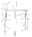
- the general reference 200 indicates an apparatus for feeding articles 17 (for example, tablets, pills, capsules, or strip packages, etc.) in a controlled configuration to a transferring line 130, in particular for feeding a container filling machine.
- articles 17 for example, tablets, pills, capsules, or strip packages, etc.
- the apparatus 200 includes means 90 for conveying the articles 17 to an inlet section 100, where working means 110 receive the articles carried by the conveying means 90, which will be better described in the following.
- the working means 110 are normally located in an initial configuration at an inlet position A, at the same level of the conveying means. After receiving the articles 17, they move vertically so as to reach an outlet position B, corresponding to an outlet section 101, in which they are coplanar with a transferring line 130 ( Figure 1) and where they are to leave the articles, as better described in the following.
- the inlet section 100 is located at a lower lever with respect to the outlet section 101.
- the apparatus 200 would operate in the same way, if the inlet section 100 were located at a level higher than the outlet section 101.
- the apparatus 200 includes a plurality of collecting magazines 102, situated in the outlet section 101 and aimed at receiving articles 17 carried by the working means 110, so as to form define corresponding piles 17a of articles 17 inside the magazines.
- the working means 110 include, for example, a transversal plate 111, operated when they have received the articles from the conveying means 90 by vertical driving means (not shown as they are of a type well known to those skilled in the art), so as to movie between the inlet configuration A and the outlet configuration B, and vice-versa when the articles have been removed therefrom.
- a transversal plate 111 operated when they have received the articles from the conveying means 90 by vertical driving means (not shown as they are of a type well known to those skilled in the art), so as to movie between the inlet configuration A and the outlet configuration B, and vice-versa when the articles have been removed therefrom.
- a plurality of longitudinal plates 112 are supported by the transversal plate 111, for receiving thereon the articles 17 carried by the conveying means 90.
- the longitudinal plates are mounted onto the transversal plate in a way such that they can slide therealong, so as to get nearer or farther from one another.
- the longitudinal plates are guided along the transversal plate by means of dove-tail guides, or similar ones.
- Guide means 113 are linked to each one of the longitudinal plates 112 so as to move them horizontally during the vertical displacement of the transversal plate 111.
- the guide means extend, for instance, in diverging directions, so that the longitudinal plates are spaced apart while the transversal plate is raised. This widening motion has the task of setting the longitudinal plates, and therefore also the articles placed thereon, at mutual distances, which match the distances between the collecting magazines 102 at the outlet section 101 (see. Figure 2).
- the guiding means 113 may include, for example, a plurality of linear cam grooves 113a, inside which a corresponding number of barrels slide, which are connected to the longitudinal plates by means of stems.
- Gripping means 112a are connected to each longitudinal plate 112 and are operated during movement of the transversal plate 111 to keep firmly the articles 17 carried by the relative longitudinal plates 112. For instance, holes connected to a source of vacuum are made in each plate 112.
- the distances between the collecting magazines 102 can be advantageously changed and its value is substantially equal to the corresponding distance between the calibrated boxes 131 made in the transferring line 130.
- Pushing means 120 for instance reciprocating pushing means, are situated in the outlet section 101 and are operated when the piles 17a of articles are completed to convey the piles 17a of articles 17, situated in each collecting magazine 102, to the calibrated boxes 131 made in the transferring line 130 for feeding the container filling machine. Endless pushing means may be used as well.
- each collecting magazine 102 includes, for example, lateral walls 102a, 102b, whose lower parts have the respective edges 12a, 12b folded so as to extend toward each other.
- the lateral walls 102a, 102b are hinged at top so that they can swing to widen and then restrict the inlet opening delimited by the folded edges, operated by power means, which are not shown as they are known to those skilled in the art.
- the transverse plate 111 with the longitudinal plates 112 and the articles 17 is about to arrive at the outlet section 101, the lateral walls are swung to open, so that the articles 17 can be positioned between the walls from the bottom.
- the lateral walls 102a, 102b are closed, thus making the relative horizontal folded edges 12a, 12b hold the piles 17a of articles 17 present inside the collecting magazines 102. Then the transverse plate 111 and the longitudinal plates 112 are moved back to inlet position A
- each collecting magazine 102 includes stationary lateral walls 102a, 102b, and elastic yielding members, which are situated at the open bottom 103.
- the elastic members when forced, allow passage of the articles 17 carried by the longitudinal plates 112, so as to define the piles 17a of articles 17and holding the piles 17a between the lateral walls 102a, 102b.
- the conveying means 90 include at least one conveying belt 91, which moves a plurality of articles 17 to the inlet section 100, to feed the longitudinal plates 112 dwelling at the inlet position A.
- the conveying belt 91 is an endless belt mounted on a driving pulley and a driven pulley.
- the conveying means 90 include a plurality of belt conveyors 91, arranged side by side, each of which is aimed at feeding a corresponding longitudinal plate 112.
- the proposed apparatus 200 feeds articles 17 in a controlled configuration to a transferring line 130, which is arranged angularly with respect to the conveying means 90.
- the transferring line 130 can be oriented longitudinally (in alignment configuration) or transversally (90° configuration) with respect to the conveying means 90.
- the proposed apparatus 200 allows the articles 17 (for example tablets, capsules, pills, strip packages) to be placed with a controlled configuration, in particular, into relative calibrated boxes 131 made in the transferring line 130, independently from the arrangement of the latter (in line or at 90°), thus allowing direct feeding of a container filling machine, without necessity of interposing any expensive apparatus.
- articles 17 for example tablets, capsules, pills, strip packages
- the apparatus 200 is set to match different levels of the outlet section 101, where the calibrated boxes 131 are made to pass as being connected to the transferring line 130, which is used each time.
- the possibility to change the distances between the collecting magazines 102 allows rapid and simple adjustment in accordance with the different distances between the boxes 131 made in the transferring line 130.
- the proposed apparatus 200 ensures high reliability and production rate in any operation conditions, and can be connected in an extremely rapid and intuitive way to the outlet section of any packaging machine.
Landscapes
- Engineering & Computer Science (AREA)
- Mechanical Engineering (AREA)
- Architecture (AREA)
- Structural Engineering (AREA)
- Basic Packing Technique (AREA)
- Auxiliary Devices For And Details Of Packaging Control (AREA)
Applications Claiming Priority (2)
| Application Number | Priority Date | Filing Date | Title |
|---|---|---|---|
| IT000075A ITBO20030075A1 (it) | 2003-02-20 | 2003-02-20 | Stazione per la fornitura di articoli in configurazione |
| ITBO20030075 | 2003-02-20 |
Publications (2)
| Publication Number | Publication Date |
|---|---|
| EP1449774A1 true EP1449774A1 (fr) | 2004-08-25 |
| EP1449774B1 EP1449774B1 (fr) | 2006-04-26 |
Family
ID=32732593
Family Applications (1)
| Application Number | Title | Priority Date | Filing Date |
|---|---|---|---|
| EP04003601A Expired - Fee Related EP1449774B1 (fr) | 2003-02-20 | 2004-02-18 | Appareil pour amener des produits à une ligne de transfert, en particulier pour alimenter une machine de remplissage de contenants |
Country Status (5)
| Country | Link |
|---|---|
| US (1) | US6964150B2 (fr) |
| EP (1) | EP1449774B1 (fr) |
| DE (1) | DE602004000709T2 (fr) |
| ES (1) | ES2264050T3 (fr) |
| IT (1) | ITBO20030075A1 (fr) |
Families Citing this family (5)
| Publication number | Priority date | Publication date | Assignee | Title |
|---|---|---|---|---|
| ITBO20030753A1 (it) * | 2003-12-16 | 2005-06-17 | Packservice S R L | Dispositivo per il trasferimento di articoli in configurazione |
| WO2005118400A1 (fr) * | 2004-06-02 | 2005-12-15 | Ferag Ag | Procede et dispositif pour emballer des objets plats |
| US20070101686A1 (en) * | 2005-11-02 | 2007-05-10 | Simone Rossi | System of package filling and sealing |
| US7698879B1 (en) * | 2008-10-06 | 2010-04-20 | Patheon Inc. | Inserter and method |
| US8046978B2 (en) * | 2009-10-02 | 2011-11-01 | R.J. Reynolds Tobacco Company | Equipment and method for packaging multiple packets of cigarettes |
Citations (1)
| Publication number | Priority date | Publication date | Assignee | Title |
|---|---|---|---|---|
| DE2523242A1 (de) * | 1974-05-27 | 1975-12-11 | Gram Brdr As | Zuliefervorrichtung fuer eine verpackungsmaschine |
Family Cites Families (14)
| Publication number | Priority date | Publication date | Assignee | Title |
|---|---|---|---|---|
| FR2039236B1 (fr) * | 1969-04-17 | 1975-06-06 | Bosch Gmbh Robert | |
| US3908539A (en) * | 1974-09-13 | 1975-09-30 | Patco Packing Ltd | Apparatus for automatically stacking and compressing batts of compressible material |
| US4034846A (en) * | 1975-04-25 | 1977-07-12 | Bunting Magnetics Company | Method and apparatus for providing automatic stacking of manufactured parts |
| JPS58171305A (ja) * | 1982-03-09 | 1983-10-08 | エー・ツエー・ハー・ウイル・ゲゼルシヤフト・ミト・ベシユレンクテル・ハフツング | 上面が開いているボール箱に堆積紙を充填するための装置 |
| JPS6347264A (ja) * | 1986-08-11 | 1988-02-29 | Yoshida Kogyo Kk <Ykk> | 長尺テ−プ状物の積重ね方法と装置 |
| DE8709053U1 (fr) * | 1987-07-01 | 1987-09-10 | Kvm Kontroll- Und Verpackungsmaschinen Gmbh & Co Kg, 7131 Wurmberg, De | |
| US4939891A (en) * | 1988-12-01 | 1990-07-10 | Piergiorgio Podini | Automatic baler for bundling together individual food bags previously filled in automatic packers |
| IT1238439B (it) * | 1990-01-26 | 1993-07-26 | Prb Packaging Systems Srl | Dispositivo per la formazione di pile verticali di articoli ordinati. |
| US5279096A (en) * | 1992-01-21 | 1994-01-18 | Machine Builders And Design Inc. | Automatic article placer and packer |
| EP0561069B2 (fr) * | 1992-03-18 | 2000-04-05 | Matsushita Electric Industrial Co., Ltd. | Méthode pour l'empilement et le transfert des plaques pour accumulateurs au plomb et dispositif |
| DE59402964D1 (de) * | 1993-04-01 | 1997-07-10 | Ferag Ag | Vorrichtung zum Verarbeiten von Druckereiprodukten |
| JP2992200B2 (ja) * | 1994-06-21 | 1999-12-20 | 花王株式会社 | 箱物品積層方法及び装置 |
| SM200100008A (it) * | 2001-03-29 | 2002-10-02 | Alkam S R L | Dispositivo per il trattamento di preforme per l'ottenimento di contenitori in plastica |
| US6574943B2 (en) * | 2001-08-17 | 2003-06-10 | Blue Print Holding B.V. | Conveyor assembly for packagings, and method for delivery of a pack |
-
2003
- 2003-02-20 IT IT000075A patent/ITBO20030075A1/it unknown
-
2004
- 2004-02-18 EP EP04003601A patent/EP1449774B1/fr not_active Expired - Fee Related
- 2004-02-18 ES ES04003601T patent/ES2264050T3/es not_active Expired - Lifetime
- 2004-02-18 DE DE602004000709T patent/DE602004000709T2/de not_active Expired - Lifetime
- 2004-02-20 US US10/783,468 patent/US6964150B2/en not_active Expired - Fee Related
Patent Citations (1)
| Publication number | Priority date | Publication date | Assignee | Title |
|---|---|---|---|---|
| DE2523242A1 (de) * | 1974-05-27 | 1975-12-11 | Gram Brdr As | Zuliefervorrichtung fuer eine verpackungsmaschine |
Also Published As
| Publication number | Publication date |
|---|---|
| US6964150B2 (en) | 2005-11-15 |
| DE602004000709T2 (de) | 2006-12-14 |
| US20040163363A1 (en) | 2004-08-26 |
| EP1449774B1 (fr) | 2006-04-26 |
| DE602004000709D1 (de) | 2006-06-01 |
| ES2264050T3 (es) | 2006-12-16 |
| ITBO20030075A1 (it) | 2004-08-21 |
Similar Documents
| Publication | Publication Date | Title |
|---|---|---|
| JP4823356B2 (ja) | 装荷回転式コンベヤを有する包装システム | |
| US4018325A (en) | Automatic package accumulator | |
| EP1553021B1 (fr) | Dispositif et procédé de remplissage d'une boîte | |
| US4443995A (en) | Metering device and method | |
| US6092979A (en) | Method and apparatus for taking over and piling articles supplied in a plurality of rows and for conveying obtained piles of articles to a packaging line | |
| US5567104A (en) | Apparatus for the transport and stocking of cigarettes | |
| US4524566A (en) | Packaging machine | |
| US11214390B2 (en) | Pouch containment and carton loading | |
| US7367172B2 (en) | Packaging machine for making and packaging articles containing a product for infusion | |
| US3760557A (en) | Carton partition forming and article handling machine | |
| US5761882A (en) | Method and apparatus for inserting flat partition elements between flanked articles | |
| US3523400A (en) | Leaflet feeder and inserter for cartoners | |
| EP1162142B1 (fr) | Dispositif pour la récupération des produits en excès d'une bande de blisters dans une machine de fabrication de blisters | |
| JPH0834413A (ja) | フォイルチューブ包装体の切断兼積重ね装置 | |
| US20100014953A1 (en) | Method and Apparatus for the Formation and Discharge of Ordered Groups of Products, in Particular Rolls of Paper | |
| US5311724A (en) | Collating apparatus | |
| EP1449774B1 (fr) | Appareil pour amener des produits à une ligne de transfert, en particulier pour alimenter une machine de remplissage de contenants | |
| AU769047B2 (en) | Device for producing and withdrawing stacks of plastic bags, especially bags for automatic machines | |
| US4395177A (en) | Apparatus for feeding folded and flattened cartons to a packaging machine | |
| RU2236997C2 (ru) | Конвейер для блистерных упаковок или стопок блистерных упаковок, имеющий приемные гнезда изменяемой высоты | |
| EP1717146B1 (fr) | Procédé et appareil pour emballer des produits | |
| US2496438A (en) | Stacking device | |
| US4009553A (en) | Machine for filling pockets | |
| US5133170A (en) | Apparatus for packing cigarettes and other smoking materials into preformed hinged lid packs | |
| GB1186778A (en) | Packaging Machine |
Legal Events
| Date | Code | Title | Description |
|---|---|---|---|
| PUAI | Public reference made under article 153(3) epc to a published international application that has entered the european phase |
Free format text: ORIGINAL CODE: 0009012 |
|
| AK | Designated contracting states |
Kind code of ref document: A1 Designated state(s): AT BE BG CH CY CZ DE DK EE ES FI FR GB GR HU IE IT LI LU MC NL PT RO SE SI SK TR |
|
| AX | Request for extension of the european patent |
Extension state: AL LT LV MK |
|
| GRAP | Despatch of communication of intention to grant a patent |
Free format text: ORIGINAL CODE: EPIDOSNIGR1 |
|
| 17P | Request for examination filed |
Effective date: 20050216 |
|
| AKX | Designation fees paid |
Designated state(s): DE ES FR IT |
|
| GRAS | Grant fee paid |
Free format text: ORIGINAL CODE: EPIDOSNIGR3 |
|
| GRAA | (expected) grant |
Free format text: ORIGINAL CODE: 0009210 |
|
| AK | Designated contracting states |
Kind code of ref document: B1 Designated state(s): DE ES FR IT |
|
| PG25 | Lapsed in a contracting state [announced via postgrant information from national office to epo] |
Ref country code: IT Free format text: LAPSE BECAUSE OF FAILURE TO SUBMIT A TRANSLATION OF THE DESCRIPTION OR TO PAY THE FEE WITHIN THE PRESCRIBED TIME-LIMIT;WARNING: LAPSES OF ITALIAN PATENTS WITH EFFECTIVE DATE BEFORE 2007 MAY HAVE OCCURRED AT ANY TIME BEFORE 2007. THE CORRECT EFFECTIVE DATE MAY BE DIFFERENT FROM THE ONE RECORDED. Effective date: 20060426 |
|
| REF | Corresponds to: |
Ref document number: 602004000709 Country of ref document: DE Date of ref document: 20060601 Kind code of ref document: P |
|
| ET | Fr: translation filed | ||
| REG | Reference to a national code |
Ref country code: ES Ref legal event code: FG2A Ref document number: 2264050 Country of ref document: ES Kind code of ref document: T3 |
|
| PLBE | No opposition filed within time limit |
Free format text: ORIGINAL CODE: 0009261 |
|
| STAA | Information on the status of an ep patent application or granted ep patent |
Free format text: STATUS: NO OPPOSITION FILED WITHIN TIME LIMIT |
|
| 26N | No opposition filed |
Effective date: 20070129 |
|
| PGFP | Annual fee paid to national office [announced via postgrant information from national office to epo] |
Ref country code: IT Payment date: 20120224 Year of fee payment: 9 |
|
| PGFP | Annual fee paid to national office [announced via postgrant information from national office to epo] |
Ref country code: DE Payment date: 20130220 Year of fee payment: 10 Ref country code: ES Payment date: 20130220 Year of fee payment: 10 |
|
| PGFP | Annual fee paid to national office [announced via postgrant information from national office to epo] |
Ref country code: FR Payment date: 20130425 Year of fee payment: 10 |
|
| REG | Reference to a national code |
Ref country code: DE Ref legal event code: R119 Ref document number: 602004000709 Country of ref document: DE |
|
| REG | Reference to a national code |
Ref country code: FR Ref legal event code: ST Effective date: 20141031 |
|
| REG | Reference to a national code |
Ref country code: DE Ref legal event code: R119 Ref document number: 602004000709 Country of ref document: DE Effective date: 20140902 |
|
| PG25 | Lapsed in a contracting state [announced via postgrant information from national office to epo] |
Ref country code: FR Free format text: LAPSE BECAUSE OF NON-PAYMENT OF DUE FEES Effective date: 20140228 Ref country code: DE Free format text: LAPSE BECAUSE OF NON-PAYMENT OF DUE FEES Effective date: 20140902 |
|
| REG | Reference to a national code |
Ref country code: ES Ref legal event code: FD2A Effective date: 20150327 |
|
| PG25 | Lapsed in a contracting state [announced via postgrant information from national office to epo] |
Ref country code: ES Free format text: LAPSE BECAUSE OF NON-PAYMENT OF DUE FEES Effective date: 20140219 |
|
| PG25 | Lapsed in a contracting state [announced via postgrant information from national office to epo] |
Ref country code: IT Free format text: LAPSE BECAUSE OF NON-PAYMENT OF DUE FEES Effective date: 20140218 |