EP1449763A1 - Method and installation of subsea effluent pollution recovery from a sunken tanker by using multiple shuttle tanks - Google Patents
Method and installation of subsea effluent pollution recovery from a sunken tanker by using multiple shuttle tanks Download PDFInfo
- Publication number
- EP1449763A1 EP1449763A1 EP03358019A EP03358019A EP1449763A1 EP 1449763 A1 EP1449763 A1 EP 1449763A1 EP 03358019 A EP03358019 A EP 03358019A EP 03358019 A EP03358019 A EP 03358019A EP 1449763 A1 EP1449763 A1 EP 1449763A1
- Authority
- EP
- European Patent Office
- Prior art keywords
- tank
- cable
- shuttle
- effluents
- closing
- Prior art date
- Legal status (The legal status is an assumption and is not a legal conclusion. Google has not performed a legal analysis and makes no representation as to the accuracy of the status listed.)
- Granted
Links
Images


Classifications
-
- B—PERFORMING OPERATIONS; TRANSPORTING
- B63—SHIPS OR OTHER WATERBORNE VESSELS; RELATED EQUIPMENT
- B63B—SHIPS OR OTHER WATERBORNE VESSELS; EQUIPMENT FOR SHIPPING
- B63B27/00—Arrangement of ship-based loading or unloading equipment for cargo or passengers
- B63B27/08—Arrangement of ship-based loading or unloading equipment for cargo or passengers of winches
-
- B—PERFORMING OPERATIONS; TRANSPORTING
- B63—SHIPS OR OTHER WATERBORNE VESSELS; RELATED EQUIPMENT
- B63C—LAUNCHING, HAULING-OUT, OR DRY-DOCKING OF VESSELS; LIFE-SAVING IN WATER; EQUIPMENT FOR DWELLING OR WORKING UNDER WATER; MEANS FOR SALVAGING OR SEARCHING FOR UNDERWATER OBJECTS
- B63C7/00—Salvaging of disabled, stranded, or sunken vessels; Salvaging of vessel parts or furnishings, e.g. of safes; Salvaging of other underwater objects
- B63C7/006—Emptying the contents of sunken, stranded, or disabled vessels, e.g. by engaging the vessel; Underwater collecting of buoyant contents, such as liquid, particulate or gaseous contents, escaping from sunken vessels, e.g. using funnels, or tents for recovery of escaping hydrocarbons
-
- E—FIXED CONSTRUCTIONS
- E02—HYDRAULIC ENGINEERING; FOUNDATIONS; SOIL SHIFTING
- E02B—HYDRAULIC ENGINEERING
- E02B15/00—Cleaning or keeping clear the surface of open water; Apparatus therefor
- E02B15/04—Devices for cleaning or keeping clear the surface of open water from oil or like floating materials by separating or removing these materials
- E02B15/08—Devices for reducing the polluted area with or without additional devices for removing the material
-
- E—FIXED CONSTRUCTIONS
- E21—EARTH DRILLING; MINING
- E21B—EARTH DRILLING, e.g. DEEP DRILLING; OBTAINING OIL, GAS, WATER, SOLUBLE OR MELTABLE MATERIALS OR A SLURRY OF MINERALS FROM WELLS
- E21B43/00—Methods or apparatus for obtaining oil, gas, water, soluble or meltable materials or a slurry of minerals from wells
- E21B43/01—Methods or apparatus for obtaining oil, gas, water, soluble or meltable materials or a slurry of minerals from wells specially adapted for obtaining from underwater installations
- E21B43/0122—Collecting oil or the like from a submerged leakage
-
- E—FIXED CONSTRUCTIONS
- E02—HYDRAULIC ENGINEERING; FOUNDATIONS; SOIL SHIFTING
- E02B—HYDRAULIC ENGINEERING
- E02B15/00—Cleaning or keeping clear the surface of open water; Apparatus therefor
- E02B2015/005—Tent-like structures for dealing with pollutant emissions below the water surface
Definitions
- the present invention relates to a recovery method and installation effluents at sea and more particularly polluting effluents contained in a ship sunk and damaged resting on the bottom of the sea.
- the ship During the sinking of tankers, the ship generally sinks after being deeply damaged and after losing part of its cargo.
- the water depth is important, for example 100 or 200 meters, the recovery of the wreck or its bailout is generally not considered, but the hull must be completely emptied and rinsed, so that corrosion of the structure in the time, creating localized or generalized holes, does not lead to the release of the contents of the ship, creating pollution that can last for years or even decades.
- the implementation of said means of positioning, during the successive descents and ascents of said receptacle represents a very long and relatively difficult operation to perform at great depth.
- pumping, through a said discharge pipe is not possible at such a depth, especially when the effluent has a high viscosity and tends to freeze under form of paraffin.
- a heating system is installed in the area of collection or in the upper part of the bell during the ascent, the viscous effluent has tendency to freeze, making pumping very difficult.
- the aim of the present invention is to provide a method and an installation allowing to recover the contents of the holds of a ship, for example an oil tanker, resting on the seabed, in significant water depths, in particular greater than 3000 meters, or even up to 4000 to 5000 meters, and which do not have the disadvantages of prior methods and devices and, in particular, which are more reliable technically, easier and simple to implement.
- said reservoir is filled with sea water before lowering it to the bottom of the sea in the deployed configuration filled with sea water.
- said effluents will be replaced by said effluents when filling said tank with effluents.
- Said rigid bottom of the tank may consist of a solid bottom comprising preferably a second orifice equipped with a second valve, where said rigid bottom can be consisting of an open frame, preferably annular, delimiting a said lower orifice main tank.
- the lower orifice can correspond to said second valve installed in the bottom full of the tank or at the openings of the peripheral envelope and if necessary said additional flexible internal pocket delimited by said open frame to which they are connected.
- Said dome with its profile in particular in the form of a shell in vertical section, associated with said buoyancy elements facilitates the ascent to the surface of the tank shuttle once full, using only clean oil buoyancy and where applicable additional buoyancy elements.
- shell profile an ellipsoid or paraboloid profile well known to those skilled in the art.
- said buoyancy elements of said shuttle tank are integrated inside said dome, said buoyancy elements preferably consisting of into syntactic foam.
- said buoyancy elements are integrated into the interior of said dome in its upper part, so that the center of buoyancy of said shuttle tank filled with effluents is shifted upwards relative to its center of apparent gravity in water.
- buoyancy center thus offset upwards, associated with the profiled shape of the dome, allows the shuttle tank to maintain, throughout its natural ascent, a substantially straight and vertical trajectory, then, on the surface, to maintain itself easily in a horizontal position to be towed and then directed towards a storage, preferably a ship with a submersible bridge, allowing the introduction of said shuttle tank of said vessel without having to remove said shuttle tank from the water.
- said shuttle tank is kept at proximity of said effluent discharge device using anchoring means, comprising at least one anchoring cable connecting at least a first fixed attachment point in the lower part of the tank, near said bottom of the tank, preferably on the periphery of said bottom of the shuttle tank and at least one second attachment point on the sunken ship, or the bottom of the sea, making it possible to anchor said shuttle tank to said sunken ship or on the bottom of the sea.
- anchoring means comprising at least one anchoring cable connecting at least a first fixed attachment point in the lower part of the tank, near said bottom of the tank, preferably on the periphery of said bottom of the shuttle tank and at least one second attachment point on the sunken ship, or the bottom of the sea, making it possible to anchor said shuttle tank to said sunken ship or on the bottom of the sea.
- Said buoyancy elements associated with said shuttle tank ensure the tensioning said cables, thereby maintaining said shuttle tank in suspension near and vertically of said opening of the hull and / or tank and, the if necessary, in cooperation with said evacuation device.
- These anchoring means can be easily implemented using an underwater vehicle controlled by distance (ROV).
- a automatic disconnection step of said anchoring means which is carried out automatically when the shuttle tank has reached a filling rate predetermined, especially when the tank is full or almost full.
- At least one said anchoring cable cooperates with a first automatic disconnection device on which traction is exerted corresponding to the Archimedes thrust exerted on said shuttle tank and its cargo, traction transmitted by said anchor cable, said disconnection device having the effect of cause a disconnection of said anchor cable by detachment of said cable anchoring with said tank or with said vessel at the bottom of the sea or by breaking the said anchor cable, and to authorize the at least partial ascent of said shuttle tank, when this traction reaches a first determined threshold value, preferably when said shuttle tank is filled with effluents.
- Cable disconnection can be done also at its end anchored on said shell or said tank, allowing release only partial allowing a rise of a limited distance from the shuttle tank , especially of a height sufficient to warn that the filling of the tank has reached the desired filling rate corresponding to the said traction threshold value.
- said first determined threshold value therefore corresponds to the Archimedes push which is exerted on the tank when the tank is filled with a predetermined quantity of effluents and, especially preferably when it is completely filled with effluents.
- said first device of automatic disconnection comprises a connection device preferably comprising a shear pin, and said connecting device provides the connection between two portions of said anchor cable, and breaks when a pull corresponding to said predetermined threshold value, is exerted on one of the two portions of said anchoring cable.
- said first device for automatic disconnection includes a link device, preferably comprising a shear pin, and said connecting device provides the connection between said cable anchor and a first point of attachment to the ship, said disconnection consisting of a break in the connection between said anchor cable and said first anchor point, then a partial release of said cable, and finally a new connection between said anchor cable and a second said point of attachment to the ship located higher than said first point fastening allowing a rise of a distance limited to the distance between the two said attachment points on the ship when a traction corresponding to said threshold value is exerted on said anchor cable at said first point of attachment to the ship.
- the rate of descent is controlled or raising of said shuttle tank with a stabilization device comprising at least a second cable or link chain, extending from the surface, preferably from a ship on the surface, to a lower part of the tank to which its end is connected, said second cable or said connecting chain comprising a portion lower weighted, preferably by blocks arranged in a chain along said second cable or by heavier large links of said chain, so that the weight of the length of said lower portion of said cable or hanging chain below said shuttle tank, can be adjusted from the surface, preferably using a winch located on board a surface vessel and on which the upper end of said cable or said chain is unwound or wound, so as to control the speed of lowering or respectively raising of said shuttle tank.
- a stabilization device comprising at least a second cable or link chain, extending from the surface, preferably from a ship on the surface, to a lower part of the tank to which its end is connected, said second cable or said connecting chain comprising a portion lower weighted, preferably by blocks arranged
- This embodiment is very advantageous because it makes it possible to control mainly the shuttle ascent rate by simply controlling the speed winding cable or chain on the surface winch. This especially allows to interrupt the recovery of the shuttle tank if the sea is too bad and, in particular, if the swell is too strong on the surface, making it impossible to transfer the tank on board the surface vessel.
- said blocks of said second cable or large heavy links of said connecting chain, in said lower portion of said second cable or chain have a shape such that when bending said cable or said chain, two blocks adjacent or two adjacent heavy links abut against each other limiting thus the local radius of curvature (Ro) of said cable or of said chain.
- This embodiment is advantageous because it makes it possible to avoid that the side wall of the tank does not strike the chain or connecting cable during operations.
- said shuttle tank comprises an additional internal pocket flexible, in which said effluents are recovered, preferably consisting of a net fine mesh, capable of confining said viscous effluents, said pocket comprising a opening capable of cooperating, by reversible connection, with said main orifice at the bottom allowing the filling of the shuttle tank.
- This embodiment with an internal pocket makes it easier to empty the shuttle tank when this has arrived at its destination on the emptying site and allows recover the flexible envelope constituting the peripheral wall of the envelope for a new round trip.
- a first closing device allows the automatic closing of said tank first valve installed in an opening of the hull or tank when said first automatic disconnection device allows at least partial ascent of said tank.
- this closing of said first valve occurs before the closing of the tank, which can be operated by an operator, especially with an ROV or trigger automatically.
- the closure of said first valve by said first closing device automatically triggers the closing of said lower orifice of the shuttle tank, preferably by said raising of said tank by a distance if necessary corresponding to the height between the two said attachment points on the ship, allowing said partial ascent.
- the closing of said lower orifice said tank is made using a second closure device comprising a cable closure forming a loop surrounding the lower end of said flexible envelope and where appropriate of the said internal pocket and allowing the tightening of the loop when a traction is exerted on said closure cable, preferably through a slip knot.
- said first device for closing said first valve includes a control cable connected at one end to a said second device for closing the tank and at its other end to a control means closing said first valve, and said control cable corresponds to in preference to the said tank closing cable forming a said loop at one end, and said control cable cooperates with a second disconnection device automatic, the latter making it possible to separate said control cable from said tank, said shell or said tank or to cause the rupture of said control cable after closing of said first valve and closing of the lower main orifice of tank.
- said disconnection of said control cable occurs when the traction exerted on said control cable at said second device disconnection reaches a second determined threshold value greater than the value necessary for actuating said means for controlling the closing of said first valve added to that required to close the tank.
- a so-called first automatic disconnection device cooperates with a said anchor cable and a said second disconnection device automatic cooperates with a said tank closing cable in a coordinated manner so that the said closing cable controls the closing of the said first valve and automatic closing of said tank by raising said full tank after said first automatic disconnection of said anchor cable, and said second disconnection of said closure cable allows complete release and ascent shuttle tank surface.
- said device for evacuating effluent is installed through an opening in the hull and / or the tank.
- the shuttle tank is manipulated by the ROV and is installed directly on the wreck making the lower orifice of said tank cooperate shuttle and the opening created in the hull, in a leaktight manner, the various elements, as well that the locking means of said elements being capable of withstanding the forces created by the overall buoyancy of the full shuttle tank of oil, as well as all stresses due to sea currents.
- said rigid bottom of the tank is advantageously made up of an open, preferably annular, block, delimiting a said lower main orifice.
- said open frame is part of a lower rigid structure frustoconical, a said cable for closing said reservoir surrounding said flexible envelope and where appropriate said internal pocket by cooperating with said structure below a level where it has a reduced diameter compared to the diameter of the current part of the cylindrical peripheral wall of a said shuttle tank.
- said shuttle tank comprises at the level from its solid bottom at least a second orifice equipped with a second valve.
- This complementary orifice makes it possible to fill said shuttle tank with sea water, once it is stowed so as to cooperate with said evacuation device and thus allowing said shuttle tank to pass from its said configuration picked up to its said deployed configuration and subsequently allowing the evacuation of sea water during filling said shuttle tank with said effluents flowing from said device discharge.
- said evacuation device cooperates with an upper port of a receptacle, said receptacle comprising a lower port positioned close and vertically to at least one second installed pipe in a said opening in the shell and / or tank so as to be able to recover said polluting effluents flowing from said opening by rising thereof in said orifice lower of said receptacle.
- This second alternative embodiment makes it possible to recover flowing effluents, in particular of several openings in said shell.
- said tank shuttle includes a solid rigid bottom and includes at the level of its said bottom, a second orifice fitted with a second valve.
- a receptacle such as described in FR 2 804 935.
- the evacuation device can be installed on an existing opening or a pre-drilled opening specially to introduce the evacuation device.
- the evacuation device is placed in the upper part of the tank. to facilitate installation of the receptacle above the end of the pipe.
- the use of a pipe allows in case of need to install the device evacuation on the side walls of the tank insofar as said pipe can be released from the side wall according to the shape that it is made to adopt.
- the skirt peripheral around the lower orifice makes it possible to cover, that is to say to cover completely said end of the pipe from above and on the sides, from so that the effluents rise well towards the open interior orifice and do not can escape.
- Said receptacle is kept in suspension close to the vertical of the opening through which the effluents flow so as to overcome the geometry of the ship and not be dependent on possible ship instability.
- All the devices described in the present invention allow the recovery of fluids immiscible or little miscible with seawater and whose density is less than 1 with respect to said seawater.
- the technology is particularly applicable to hydrocarbons whose density varies from 0.75 for the lightest, to values close to 1 for the heaviest.
- the present invention also relates to the installation useful in a method of recovery of polluting effluents contained in the tanks of a sunken ship and / or damaged lying at the bottom of the sea according to the invention, characterized in that it comprises a said shuttle tank as defined above and, preferably, said anchoring means, as defined above.
- said installation comprises Installation, a said device for stabilization comprising at least one said second cable or link chain.
- said installation comprises a said first device for closing and a said first disconnection device, and where appropriate a said second tank closing device.
- said installation comprises a said receptacle and where appropriate, said anchoring means and said means of positioning and so-called tensioning means.
- FIG. 1 the hull of a wreck or a wall of tank 6 resting on the bottom of the sea 7 filled with hydrocarbon 1 whose density is lower than sea water. Said hydrocarbon is confined in the part upper part of the tank or wreck 6, the lower part being filled with water sea.
- the ship generally having multiple closed openings tightly at the deck, leaks may occur as soon as this seal would be degraded by deformation or rupture of the hull during the sinking.
- an evacuation device 6 1 -6 4 of the effluents comprising a pipe 6 4 fitted with a first valve 6 1 and a pipe 6 2 fitted at its end of a connection flange 6 3 to which is connected a corresponding flange 5 3 secured to a shuttle tank 2, at its lower part.
- an evacuation device 6 1 -6 4 of the effluents is done for example according to the so-called "hot tap” technique, that is to say hot or charged tapping.
- This technique consists in fixing directly on the outside of the tank, for example by welding, a short length of pipe 6 2 equipped with a full-flow valve 6 1 .
- a special machine, not shown, is then installed in the axis of said pipe is y and connected in a sealed manner.
- the machine is equipped with a drilling machine which, using a tool, will reach the wall of the tank and drill a hole in it, generally with a diameter corresponding to that of the pipe.
- the drill bit is released, the valve closed and the machine can then be dismantled to be replaced by a pipe 6 2 , rigid or flexible which will allow the product to be evacuated, without any leakage. has been generated.
- the evacuation device described above can be lowered onto the wreck and temporarily stabilized by a dead body, a suction bell device, or a magnetic device, then when the hole has been drilled, said evacuation device.
- 6 1 -6 4 is locked permanently by fingers actuated by the ROV, in particular by resting, from inside the duct, on the internal face of the hole in the shell and firmly and sealingly pressing said device on the wall of the wreck.
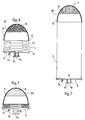
- Said shuttle tank 2 is shown in FIGS. 1 to 4 and is made up of a flexible and watertight side wall 4, for example made of high strength reinforced plasticized fabric, secured in the upper part of a dome 3 with circular horizontal section and with profile in vertical section in the form of a shell made of a resistant and rigid material, preferably of composite material, and integral in the lower part of a bottom 5, flat, solid, resistant and rigid, preferably circular, too preferably in composite material, so as to represent a minimum apparent weight in water, while guaranteeing extreme rigidity and resistance.
- a flexible and watertight side wall 4 for example made of high strength reinforced plasticized fabric, secured in the upper part of a dome 3 with circular horizontal section and with profile in vertical section in the form of a shell made of a resistant and rigid material, preferably of composite material, and integral in the lower part of a bottom 5, flat, solid, resistant and rigid, preferably circular, too preferably in composite material, so as to represent a minimum apparent weight in water, while guaranteeing extreme rigidity and resistance.
- Said bottom 5 is pierced in its center with a main orifice 5 1 and is equipped with a valve 5 2 , preferably with full passage, for example of the ball valve type, the latter being equipped with a flange 5 3 .
- a complementary lateral orifice of smaller diameter is provided with a valve 5 4 , thus allowing the exchange of sea water between the interior of the shuttle tank and the marine environment, and in particular when filling the tank with oil, to the sea water to escape.
- the dome 3 and the bottom 5 can have a diameter of 5 to 10 m, the dome 3 a height of 2 to 5 m and the side wall 4, when unfolded, a height of 10 at 50 m.
- main orifice 5 1 and its associated valve 5 2 for example 10 to 24 ", or even more, and one or more complementary orifices of 1 to 4 "fitted with 5 4 valves of corresponding diameter.
- the shuttle tank 2 is shown in the deployed position (2B) in Figure 2, the main valve 5 2 with full passage being in the open position.
- FIG. 3 there is shown in sectional side view the shuttle tank 2 in the final phase of preparation before use, that is to say before it is put in the water and its descent to the wreck or tank 6.
- a multiplicity of folds 4 1 is created distributed over the periphery, which makes it possible to reduce the length of the shuttle tank by bringing the bottom 5 closer to the dome 3.
- the bottom 5 and the dome 3 are brought as close as possible to obtain a shuttle tank 2 in the picked up position (2A), therefore occupying a minimum of volume, which presents a considerable advantage for its handling, for its descent to the wreck or tank 6 and for its installation on the evacuation devices 6 1 -6 4 which have been prepared on the hull of said wreck or wall of said tank 6.
- the shuttle tank 2 is firmly held by straps 7 connecting the bottom 5 and the dome 3 each equipped with hooks 7 1 at their periphery.
- the apparent weight in the water of the shuttle tank 2 is advantageously adjusted by incorporating buoyancy, for example syntactic foam 3 1 , made up of glass microspheres coated in epoxy resins, into the highest part of the dome 3, polyurethane or others.
- buoyancy for example syntactic foam 3 1 , made up of glass microspheres coated in epoxy resins, into the highest part of the dome 3, polyurethane or others.
- the shuttle tank 2 is lowered towards the wreck or tank 6 in the picked up position (2A), and has a very low apparent weight in the water and which can be adjusted in positive as in negative, which facilitates its installation directly.
- a ROV 30 automated submarine piloted from the surface and equipped with manipulator arms.
- the ROV manipulates the shuttle tank so as to make the flange 5 3 integral with the lower orifice 5 1 of the bottom 5 of said shuttle tank 2 coincide, and the corresponding flange 6 3 of said evacuation device installed on the hull of the 'wreck or tank wall 6, then the two flanges 5 3 and 6 3 are locked together to seal the connection.
- the shuttle tank 2 is positioned by the ROV near the wreck and above the evacuation device 6 1 -6 4 using cables 12 1 coming from winches 14 1 installed on the shell or wall of the tank 6 or close to it, and connected to attachment ears 13 1 secured to the bottom 5 of said shuttle tank 2.
- winches 14 1 By acting on the winches 14 1 , the shuttle tank 2 of its connection point constituted by the fixed flange 6 3 installed on the hull of the wreck or tank wall 6, then the two flanges 5 3 , 6 3 are locked using the ROV.
- the main valve 5 1 with integral passage integral with the bottom 5 of the shuttle tank 2 is then open, likewise the valve 6 1 of the evacuation device located on the hull of the wreck or tank wall 6, which, by simple density difference effect between petroleum 1 and sea water, transfers said petroleum 1 upwards, that is to say completes the filling of said shuttle tank. During filling, the corresponding volume of seawater escapes through the additional lateral opening 5 4 .
- the shuttle tank 2 is allowed to rise naturally towards the surface because, the shell shape of the dome 3, associated with the buoyancy created by the syntactic foam 3 1 integrated into the dome 3 and the weight of the bottom 5, including in particular the flange 5 3 connection and the main valve 5 2 with ball valve, shifts up the center of buoyancy and downwards the apparent center of gravity in the water, which allows the shuttle tank 2 to keep during all the ascent substantially straight and vertical trajectory, as shown in FIG. 5.
- the shuttle tank 2 arriving at the surface 11 then floats naturally and can be taken in tow, then directed towards a storage ship 10, preferably a ship with a submersible bridge.
- a storage ship 10 preferably a ship with a submersible bridge.
- Such a ship with a submersible bridge allows ballasting to maintain the main deck under several meters of water, thus allowing the packages to be transported by flotation, then by deballasting remove the bridge from the water and carry out the transport. "dry" packages.
- Such ships are available from many owners; for example Mamoeth (Holland).
- the shuttle tank 2 is completely free and uncontrollable, it can surface anywhere in the area of operations, and, to avoid any incident, the dome of the shuttle tank is advantageously fitted with a acoustic transponder, so as to be able to locate, during the entire phase of lift, said shuttle tank and thus avoid any collision, by moving the if necessary, the various vessels operating on the surface.
- the shuttle tanks 2 are advantageously stored side by side on simple supports and thus secured with the deck of the carrier ship 10.
- Ship 10 once loaded, is deballasted, then directed to a port where it is reballasted to effect the transfer shuttle tanks to recovery units. Once released, the ship returns to site for a new load.
- the shuttle tanks 2 are maintained in buoyancy and preferably led into an isolated retention basin, with a view to being emptied of their contents, to avoid any pollution of the environment.
- the emptying is advantageously carried out horizontally, the shuttle tank 2 still being in flotation, by connecting, on the flange 5 3 secured to the bottom 5 of the shuttle tank 2, a pipe, preferably flexible, connected to the pumping system.
- the recovered oil is generally extremely viscous
- emptying is facilitated by creating a heating of the area close to the outlet orifice 5 1 of the shuttle tank 2, for example by injecting a hot fluid through the complementary lateral orifice 5 4 , said hot fluid preferably being crude oil brought to high temperature, that is to say 80 to 100 ° C., which makes it possible to fluidize the viscous oil located near the outlet orifice.
- a hot fluid preferably being crude oil brought to high temperature, that is to say 80 to 100 ° C., which makes it possible to fluidize the viscous oil located near the outlet orifice.
- the shuttle tank 2 is in the intermediate position (2C) as shown in Figure 3, then it is picked up (2A) as shown in Figure 4 and the assembly is firmly held by straps 7 connecting the bottom 5 and the dome 3. The shuttle tank 2 is again ready to be sent back to the site for a new filling cycle.
- Said receptacle 20 is in the form of an inverted umbrella or a funnel of circular or trapezoidal section which covers an entire area comprising several openings emitting polluting effluents.
- the size of the funnel of the receptacle 20 can correspond to a diameter of about 25 to 50 m, or even more, and a height of about 25 to 50 m also. It consists of a rigid frame associated with a flexible membrane or a rigid funnel-shaped structure, the upper part 17 of which is equipped with an evacuation device 6 1 -6 3 comprising a valve 6 1 with a pipe 6 2 fitted at its upper part with a flange 6 3 cooperating with a corresponding flange 5 3 at the bottom 5 of the shuttle tank 2.
- the bell 20 is held in position by a set of cables 12 2 connected, on the one hand, to a fastener 13 2 secured to the bell and, on the other hand, to a winch 14 2 on the tank or the wreck 6
- These cables preferably 3 cables, are installed to form a pyramid, preferably with an equilateral triangular base.
- the position of said bell can be adjusted and kept as close as possible to the wreck, for example at 50 cm or 1 m, so that the lower end of the large open base of the funnel which constitutes the peripheral skirt defining the lower opening 19 of said receptacle 20 can cover an additional evacuation device comprising a pipe 6 4 with valve 6 5 installed in the wall of the tank or wreck 6 as shown in FIG.
- Said receptacle 20 is made floating by means such as buoys 15, 16 in syntactic material resistant to bottom pressure or by buoys hollow in various materials, such as plastics, steel or materials composites.
- the receptacle is held in position using a peripheral float 16 surrounding the tubular upper part of the funnel and a series of floats 15 connected to the circumference of the large base of the funnel in its lower part.
- Said receptacle 20 comprises heating means 21 for said effluents pollutants 1 to make them less viscous and thermal insulation means of its outer wall 22.
- an additional heating system 6 6 is advantageously installed in the collection zone 6 4 , thus than in the upper part of the bell 20, the outside of said bell preferably being protected by thermal insulation 22.
- An assistance vessel 31 provides the power necessary for reheating and the operation of ROV 30 via an umbilical 32, as explained in Figure 7.
- the attachment points on the wreck or tank 6 and in particular the winches 14 1 and 14 2 are advantageously fixed to the wreck using a suction box comprising an open face at the interface with the wreck and which cooperates therewith by a peripheral seal and a suction pipe making it possible to create a vacuum in the interior of the box.
- a suction box comprising an open face at the interface with the wreck and which cooperates therewith by a peripheral seal and a suction pipe making it possible to create a vacuum in the interior of the box.
- a suction box comprising an open face at the interface with the wreck and which cooperates therewith by a peripheral seal and a suction pipe making it possible to create a vacuum in the interior of the box.
- the pipe can either be in communication with a pump installed on ROV, either replaced by a pump secured to the suction box and supplied by said ROV or directly from the service vessel installed on the surface.
- the shuttle tank 2 has a removable bottom 5 connected, for example by means of bolts not shown, to a peripheral flange 5 5 secured to the lower end of the flexible side wall 4
- an internal pocket 2 1 is advantageously installed constituting, by itself, a second flexible envelope, of dimensions similar or even slightly smaller than those of the external envelope constituted by the whole of the dome 3 of the flexible side wall 4 and of the bottom 5 of the shuttle tank 2.
- Said pocket 2 1 consists of a fine mesh net, having a single opening downwards, the latter coming to cooperate with a portion of pipe 5 6 in continuity from the main port 5 1 from the bottom 5 of the shuttle tank 2 inwards.
- Said second inner envelope or pocket 2 1 is made integral with said pipe portion 5 6 by a strap 5 7 .
- each of the shuttle tanks 2 When the shuttle tanks 2 have been unloaded in the recovery port site, each of the shuttle tanks is towed horizontally into the retention basin, then, still in a horizontal position, a ring 3 2 secured to the dome 3 is connected to a mooring point 9 secured to the edge of the basin; the fixing bolts, or the latches of the flange 5 5 , connecting the flexible side wall 4 and the bottom 5 of the shuttle tank 2, are then released, then the whole of the bottom 5, secured to the internal pocket 2 1 , and the dome 3, integral with the side wall 4, constituting an external envelope, are separated over a few meters.
- a link made with a simple cord is tightened around the lower orifice of the pocket 2 1 at the level of the plane AA, passing through eyelets 5 8 , then tightened firmly so as to close, tightly, the pocket.
- the pocket 2 1 is then separated from the bottom 5 of the shuttle tank 2 by loosening the strap 5 7 , and said bottom 5 is removed.
- the pocket 2 1 is then completely removed from the shuttle tank 2.
- the shuttle tank is then released and, after reinstallation of a new internal pocket 2 1 , strapped 5 7 on the bottom 5 of said shuttle tank 2, the latter is re-assembled using bolts on an external envelope, consisting in the dome 3 secured to the flexible side wall 4, and the assembly is then ready to be placed in the picked up position (2A) as explained in FIGS. 3 and 4.
- the pocket 2 1 once extracted, floats within the retention basin. It is then directed, still in flotation, towards a cradle, which will then be extracted from the basin using a high capacity crane, to be transferred, after draining the residual water, to a second retention basin where the bag will be unloaded in order to be prepared, either to be eliminated, or to be treated for the reuse of some of its constituents.
- FIG. 10 illustrates a preferred version of the invention, in which the ascent of the shuttle tank is controlled by a connecting cable 30, a portion of its part lower is weighed down, for example, by metal blocks 31 secured to said cable 30 by a crimp at 31, in a chain like beads on a cable.
- These pearls 31 have a cylindrical prismatic or revolutionary central body and, frustoconical ends such that when the cable is bent, said frustoconical ends of the two adjacent pearls then come into abutment against one another at 31 2 , limiting thus the local radius of curvature to a value greater than R 0 .
- the connecting cable 30 being hooked to the shuttle tank 2 on said first attachment point 32 in the lower part of the tank, descends downwards then deviates in an arc of a circle of radius R 0 , to finally ascend vertically or in chain configuration at a distance of at least about 2R 0 from the side wall 4 of said shuttle tank, thus avoiding any mechanical contact during the ascent, which avoids damaging it by friction.
- the buoyancy of the shuttle tank filled with hydrocarbons F v which corresponds to the buoyancy exerted on the tank and its cargo, is compensated by the weight of the cable up to the corresponding horizontal point of tangency to the pearl 31 i , added to the weight of the pearls 31 g between the reservoir and the lowest pearl 31 i, that is to say 8.5 pearls in FIG. 10, the weight of the assembly P e then corresponding to a balance of the system.
- Each of the beads of the balancing device 30-31 then has a weight in water about 1 ton.
- FIG. 11 the upper end of the connecting cable 30, connected to a winch installed on board a surface vessel (not shown) is raised, which has the effect of bringing the pearl 31 g of the figure 10 in the low horizontal position, thereby reducing the number of beads weighing under the tank to 6.5 beads, the overall weight opposing the thrust Fv then being reduced to P inf .
- the resultant F v + P inf is then positive upwards and the shuttle reservoir can rise until the balance of forces in FIG. 10 is reached.
- the upper end of the connecting cable 30 is deflected, which has the effect of bringing the pearl 31 k into the low horizontal position, thereby increasing the number of pearls weighing under the reservoir at 10.5 pearls, the overall weight then being equal to P sup .
- the resultant F v + P sup is then positive downwards and the shuttle tank can descend again until the balance of forces in FIG. 10 is reached.
- the stabilization device has a stabilizing effect for raising the shuttle tank.
- the surface vessel moves excessively under the effect of the swell or deviates from the vertical of the position of the shuttle tank, the movements have an instantaneous effect only on the zone of the pearls surrounding the pearls 31 9 at 31 k , the pearl 31 i corresponding to the average value of the oscillations.
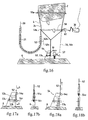
- FIG. 13 represents the section in side view of a shuttle tank 2 installed vertically of a said pipe 6 4 equipped with a first valve 6 1 secured to the wreck, said first valve being in the open position and passing the crude oil which is collected in the shuttle tank.
- the bottom of the tank comprises an open annular frame delimiting a said lower main orifice 5 1 .
- the lower part of the envelope of the shuttle tank is held in shape by a rigid lower structure 51d forming a double cone 50a - 50b kept in shape arranged under the bottom of the tank, constituted by circular stiffeners 51 a - 51 b -51 c connected by a lattice structure 51d, not shown in Figure 13, but shown in Figure 15.
- the shuttle tank is held above the wreck by means of an anchor cable 52-52 1 secured to the wreckage at a said second anchor point 54 and at its upper part, of a said first automatic load limiter disconnection device 53 itself connected to the shuttle tank via a crow's feet 52-52 2
- the load limiting device 53 is illustrated in 13a and comprises a lower yoke 53 1 connected to an upper bar 53 2 to which is connected, by means of a shear pin 53 3 of known limiting load.
- the buoyancy of the assembly will increase until reaching the maximum value F v , value corresponding to the resistance limit of the pin 53 3 , which breaking, will release the shuttle tank which then will begin its ascent.
- a control cable 56, 56.1 was advantageously connected to a lever arm 57 controlling the closing operation of said first valve 6 1 , the upper part of the cable is integral with the structure of the shuttle tank.
- the cable 56.56 1 actuates the lever 57 and thus closes the valve 6 1 , as illustrated in FIG. 14.
- the upper portion 56 2 of the cable 56 is advantageously connected to the external envelope by a loop 58 surrounding the said envelope and passing through a loose slip knot situated in the plane AA of FIG. 15, thus acting as a cable for closing the lower main port of the tank.
- FIG. 15 is a section for below according to plan AA.
- the shearing of the pin of said first automatic disconnection device 53 will then be adjusted for a value of approximately 8.5 tonnes.
- the second device disconnection 60 will advantageously be adjusted to a so-called second traction threshold value 1.5 tonnes, i.e. more than 1 ton but less than 8.5 tonnes, so that that the previously described sequences take place automatically in order indicated.
- said rigid lower structure 51 d forms a double truncated cone 50a, 50b formed by two upper cone 50b and lower 50a cones, with flaring up and down respectively, joined by their small base common at an intermediate circular frame 51b of said rigid lower structure, so that said closure loop 58 which surrounds the lower end of the flexible envelope 4 or so-called pocket 2 1 , must travel a reduced stroke to close the main lower port of the tank.
- the lower end of the reservoir comprises an open annular frame 51.b delimiting the lower main orifice 5 1 of the reservoir and to which the lower end of the envelope is connected flexible constituting the lateral peripheral wall of the reservoir as well as the lower end of the internal pocket 2 1 .
- the installation comprises a said first automatic disconnection device consisting of a frame 54 secured to the wreck 6 acting as said second attachment point, comprising at its lower part a first hook constituting a first point of attachment 54 1 and in its upper part a second hook constituting a second attachment point 54 2 located at a height of 0.5 to 1 m above the first hook.
- Said first hook 54 1 is located at the end of a second lever 53 5 , articulated at 53 6 , said lever 53 5 being held in a substantially horizontal position by a shear pin 53 4 making it integral with the frame 54.
- L the lower end of the anchoring cable 52 forms a loop engaged in the said first hook 54 1 located on the underside, at the end of the lever 53 5 , and envelops the upper part of the frame 54 in the area of the second hook 54 2 , as explained in Figures 17a and 17b.
- valve 6 1 is in the open position, but as soon as the shuttle tank is released by breaking the shear pin 53 4 , the upward movement of the shuttle closes said first valve by means of the control and closing cable 56 integral with the lever 57 for controlling said first valve.
- the shuttle tank is then on standby in the safety position of FIG. 18 retained by the first hook 54 1 .
- the pocket 2 1 is closed by tightening the loop 58 in the slip knot as explained previously in FIG. 15, by means of a small winch 62 secured to the shuttle tank 2, said winch being actuated by the ROV 30.
- the ROV manipulator arm fitted with a shear, cuts the control and closing cable 56, as well as the anchoring cable 52, which has the effect of completely freeing the shuttle tank which can then be raised to the surface thanks to the weighted chain 30-31.
- the pin 53 4 shears and the shuttle tank finds itself on standby, still open, in the position indicated in FIGS. 18a and 18b.
- the surface operator is thus warned (via a camera on board the ROV) of the end of filling and under the control of said video camera of the remotely controlled underwater vehicle (ROV), it is then simple to let it fill as much as possible before the valve is closed by said ROV.
- the automatic disconnection system then only plays a role of control system for filling the shuttle tank, most of the final control, closing and release operations of the shuttle tank being carried out directly by said ROV 30.
- Automatic disconnection devices 53 have been described comprising a shear pin, but we remain in the spirit of the invention by considering systems, load sensor systems, either based on the compression of a spring, either on an electronic or hydraulic component giving a proportional response to the load applied and causing the release of the retaining cable 52 by triggering.
- valve 6 1 installed on the orifice integral with the hull of the wreck is a ball valve, but we remain in the spirit of the invention by considering any other type of valve, such as knife gate valves, diaphragm valves or any other device to prevent crude oil from leaving the hull in an uncontrolled manner.
- the operating means of said valve have been described as being a lever arm 57, but it remains in the spirit of the invention by using cable, pulley or screw systems, or also rack systems, for close said valve 6 1 .
Abstract
Description
La présente invention concerne un procédé et une installation de récupération d'effluents en mer et plus particulièrement d'effluents polluants contenus dans un navire coulé et endommagé reposant au fond de la mer.The present invention relates to a recovery method and installation effluents at sea and more particularly polluting effluents contained in a ship sunk and damaged resting on the bottom of the sea.
Lors du naufrage des pétroliers, le navire coule en général après avoir été profondément endommagé et après avoir perdu une partie de sa cargaison. Lorsque la profondeur d'eau est importante, par exemple 100 ou 200 mètres, la récupération de l'épave ou son renflouement, n'est en général pas envisagée, mais la coque doit être intégralement vidée et rincée, de manière à ce que la corrosion de la structure dans le temps, créant des trous localisés ou généralisés, ne conduise à la libération du contenu du navire, créant ainsi une pollution pouvant se prolonger sur des années, voire des décennies.During the sinking of tankers, the ship generally sinks after being deeply damaged and after losing part of its cargo. When the water depth is important, for example 100 or 200 meters, the recovery of the wreck or its bailout is generally not considered, but the hull must be completely emptied and rinsed, so that corrosion of the structure in the time, creating localized or generalized holes, does not lead to the release of the contents of the ship, creating pollution that can last for years or even decades.
De nombreux procédés et dispositifs ont été étudiés et utilisés dans le passé pour essayer de récupérer des cargaisons hautement polluantes, mais tous sont, soit non fiables techniquement, soit très délicats à mettre en oeuvre et les opérations prennent beaucoup de temps et engendrent en général des pollutions secondaires, car le taux de récupération est loin d'être satisfaisant, et ce d'autant plus que le procédé doit être mis en oeuvre à grande profondeur.Many methods and devices have been studied and used in the past for try to recover highly polluting cargoes, but all are either not technically reliable, very delicate to implement and operations take a lot of time and generally cause secondary pollution, because the rate of recovery is far from satisfactory, especially since the process must be implemented works at great depth.
En particulier, on a décrit, dans FR 2 804 935 au nom de la demanderesse, un
procédé de récupération d'effluents polluants, plus légers que l'eau et peu ou non
miscibles à l'eau, contenus dans une cuve d'un navire coulé et/ou endommagé reposant
au fond de la mer, qui comprend les étapes suivantes dans lesquelles:
Dans une première variante de réalisation décrite dans FR 2 804 935 :
- des moyens d'ancrage dudit réceptacle sur le navire comprenant des câbles reliant des points d'attache fixés sur la circonférence de ladite grande base de l'entonnoir et des points d'attache sur le navire, et
- des moyens de tensionnement comprenant :
- des flotteurs reliés à la circonférence de ladite grande base ouverte dudit réceptacle et autour de la section tubulaire en partie supérieure de la petite base dudit entonnoir, et
- des treuils correspondants aux dits points d'attache sur le navire, et
- means for anchoring said receptacle to the ship comprising cables connecting attachment points fixed on the circumference of said large base of the funnel and attachment points on the ship, and
- tensioning means comprising:
- floats connected to the circumference of said large open base of said receptacle and around the tubular section in the upper part of the small base of said funnel, and
- winches corresponding to the said attachment points on the ship, and
Dans cette première variante de réalisation, la mise en oeuvre desdits moyens de positionnement, lors des descentes et remontées successives dudit réceptacle, représente une opération très longue et relativement malaisée à réaliser à grande profondeur. En outre, le pompage, à travers une dite conduite d'évacuation, n'est pas possible à une telle profondeur, en particulier dès que l'effluent a une forte viscosité et a tendance à figer sous forme de paraffine. Même si on installe un système de réchauffage dans la zone de captage ou dans la partie haute de la cloche lors de la remontée, l'effluent visqueux a tendance se figer, rendant le pompage très difficile.In this first alternative embodiment, the implementation of said means of positioning, during the successive descents and ascents of said receptacle, represents a very long and relatively difficult operation to perform at great depth. In in addition, pumping, through a said discharge pipe, is not possible at such a depth, especially when the effluent has a high viscosity and tends to freeze under form of paraffin. Even if a heating system is installed in the area of collection or in the upper part of the bell during the ascent, the viscous effluent has tendency to freeze, making pumping very difficult.
Dans une deuxième variante de réalisation décrite dans FR 2 804 935, ledit réceptacle consiste en :
- un conteneur rigide de forme sensiblement tubulaire, qui est maintenu en position verticale à l'aide de flotteurs installés au moins à l'extrémité supérieure ou à chaque extrémité supérieure et inférieure dudit conteneur, et
- lesdits orifices supérieur et inférieur dudit conteneur étant obturables de sorte que ledit réceptacle peut être remonté en surface et installé en position horizontale flottante lorsque lesdits orifices sont obturés, ledit réceptacle pouvant alors être remorqué vers une installation ou un navire de stockage desdits effluents.
- a rigid container of substantially tubular shape, which is held in vertical position by means of floats installed at least at the upper end or at each upper and lower end of said container, and
- said upper and lower orifices of said container being closable so that said receptacle can be raised to the surface and installed in a floating horizontal position when said orifices are closed, said receptacle can then be towed to an installation or a vessel for storing said effluents.
Ces conteneurs rigides en forme dénommée cigare, de par leur encombrement important, sont difficiles à descendre au fond de la mer et, pour éviter les opérations successives, on a décrit un mode préférentiel dans lequel ledit conteneur occupe toute la tranche d'eau entre l'épave et la surface. Mais, il est évident que cette deuxième variante de réalisation ne peut être envisagée pour des profondeurs de 1000 mètres ou plus, car elle implique un réceptacle beaucoup trop volumineux, impossible à installer ou à descendre fréquemment.These rigid containers in the form of a cigar, due to their size important, are difficult to descend to the bottom of the sea and, to avoid operations successive, a preferred mode has been described in which said container occupies all of the slice of water between the wreck and the surface. But, it is obvious that this second variant cannot be considered for depths of 1000 meters or more, because it involves a receptacle that is far too large, impossible to install or go down frequently.
En pratique, les différents modes de réalisation décrits dans FR 2 804 935, ne
conviennent pas pour des interventions à des profondeurs supérieures à 1000 mètres.In practice, the different embodiments described in
Le but de la présente invention est de fournir un procédé et une installation permettant de récupérer le contenu des soutes d'un navire, par exemple un pétrolier, reposant sur le fond marin, dans des profondeurs d'eau importantes, notamment supérieures à 3000 mètres, voire jusqu'à 4000 à 5000 mètres, et qui ne présentent pas les inconvénients des procédés et dispositifs antérieurs et, en particulier qui soient plus fiables techniquement, plus aisés et simples à mettre en oeuvre.The aim of the present invention is to provide a method and an installation allowing to recover the contents of the holds of a ship, for example an oil tanker, resting on the seabed, in significant water depths, in particular greater than 3000 meters, or even up to 4000 to 5000 meters, and which do not have the disadvantages of prior methods and devices and, in particular, which are more reliable technically, easier and simple to implement.
Pour ce faire, la présente invention fournit un procédé de récupération d'effluents
polluants plus légers que l'eau, contenus dans une cuve d'un navire coulé et/ou
endommagé reposant au fond de la mer dans lequel :
Selon la présente invention, à l'étape b) on récupère lesdits effluents à l'aide d'un
réservoir navette, pouvant adopter une configuration ramassée et une configuration
déployée, ledit réservoir navette comprenant au moins un orifice principal inférieur apte à
coopérer avec ledit dispositif d'évacuation, de sorte que l'on réalise les étapes dans
lesquelles :
L'utilisation d'une navette réservoir pouvant adopter une configuration ramassée, c'est-à-dire de faible encombrement, rend aisée sa descente au fond de la mer, et le cas échéant la solidarisation avec l'épave, notamment en connectant ledit orifice inférieur de la navette réservoir avec ledit dispositif d'évacuation, notamment à l'aide d'un ROV. D'autre part, ce dit réservoir navette, de par la flottabilité propre du pétrole et de ses éléments de flottabilité complémentaires éventuels, permet la remontée des effluents sans l'utilisation d'une conduite de liaison fond-surface et/ou sans pompage, depuis la surface, des effluents à récupérer.The use of a tank shuttle that can adopt a picked up configuration, that is to say compact, makes it easy to descend to the bottom of the sea, and the case where appropriate, the connection with the wreck, in particular by connecting said lower orifice of the tank shuttle with said evacuation device, in particular using an ROV. Else share, this so-called shuttle tank, due to the clean buoyancy of oil and its elements possible additional buoyancy, allows the effluent to rise without the use a bottom-surface connection pipe and / or without pumping, from the surface, effluents to be recovered.
Dans un mode de réalisation particulier, on remplit ledit réservoir d'eau de mer avant de le descendre au fond de la mer en configuration déployée remplie d'eau de mer. Ainsi, ultérieurement, au fond de la mer, on remplacera l'eau de mer par desdits effluents lors du remplissage dudit réservoir en effluents.In a particular embodiment, said reservoir is filled with sea water before lowering it to the bottom of the sea in the deployed configuration filled with sea water. Thus, later, at the bottom of the sea, the sea water will be replaced by said effluents when filling said tank with effluents.
Dans un mode particulier de réalisation, ledit réservoir navette comprend:
- ladite paroi périphérique latérale peut être repliée sur elle-même, pour permettre le rapprochement dudit dôme et dudit fond, de préférence à l'aide de sangles amovibles, ledit réservoir navette étant alors en dite position ramassée et
- lesdits effluents pouvant être confinés à l'intérieur dudit réservoir navette lorsque ladite paroi latérale est dépliée, ledit réservoir navette étant alors en dite position déployée.
- said lateral peripheral wall can be folded back on itself, to allow said dome and said bottom to be brought together, preferably by means of removable straps, said shuttle tank then being in said picked up position and
- said effluents being able to be confined inside said shuttle tank when said side wall is unfolded, said shuttle tank then being in said deployed position.
Ledit fond rigide du réservoir peut être constitué par un fond plein comportant de préférence un second orifice équipé d'une seconde vanne, où ledit fond rigide peut être constitué d'un cadre ouvert, de préférence annulaire, délimitant un dit orifice inférieur principal du réservoir.Said rigid bottom of the tank may consist of a solid bottom comprising preferably a second orifice equipped with a second valve, where said rigid bottom can be consisting of an open frame, preferably annular, delimiting a said lower orifice main tank.
L'orifice inférieur peut correspondre à ladite deuxième vanne installée dans le fond plein du réservoir ou aux ouvertures de l'enveloppe périphérique et le cas échéant de ladite poche interne additionnelle souple délimitées par ledit cadre ouvert auquel elles sont reliées.The lower orifice can correspond to said second valve installed in the bottom full of the tank or at the openings of the peripheral envelope and if necessary said additional flexible internal pocket delimited by said open frame to which they are connected.
Ledit dôme, avec son profil notamment en forme d'obus en section verticale, associé aux dits éléments de flottabilité facilite la remontée vers la surface du réservoir navette une fois plein, à l'aide de la seule flottabilité propre du pétrole et le cas échéant des éléments de flottabilité complémentaires.Said dome, with its profile in particular in the form of a shell in vertical section, associated with said buoyancy elements facilitates the ascent to the surface of the tank shuttle once full, using only clean oil buoyancy and where applicable additional buoyancy elements.
On entend, ici, par profil en obus : un profil en forme d'ellipsoïde ou de paraboloïde bien connu de l'homme de l'art.Here, we mean by shell profile: an ellipsoid or paraboloid profile well known to those skilled in the art.
Avantageusement, lesdits éléments de flottabilité dudit réservoir navette sont intégrés à l'intérieur dudit dôme, lesdits éléments de flottabilité consistant, de préférence, en de la mousse syntactique.Advantageously, said buoyancy elements of said shuttle tank are integrated inside said dome, said buoyancy elements preferably consisting of into syntactic foam.
Plus avantageusement encore, lesdits éléments de flottabilité sont intégrés à l'intérieur dudit dôme dans sa partie supérieure, de sorte que le centre de flottabilité dudit réservoir navette rempli d'effluents est décalé vers le haut par rapport à son centre de gravité apparent dans l'eau. Even more advantageously, said buoyancy elements are integrated into the interior of said dome in its upper part, so that the center of buoyancy of said shuttle tank filled with effluents is shifted upwards relative to its center of apparent gravity in water.
On installe suffisamment de flottabilité et en position suffisamment haute pour que le centre de flottabilité, ainsi décalé vers le haut, associé à la forme profilé du dôme, permette au réservoir navette de conserver, pendant toute sa remontée naturelle, une trajectoire sensiblement rectiligne et verticale, puis, arrivé en surface, de se maintenir facilement en position horizontale pour être pris en remorque puis dirigé vers un navire de stockage, de préférence un navire à pont submersible, permettant d'introduire ledit réservoir navette dudit navire sans avoir à sortir ledit réservoir navette de l'eau.We install enough buoyancy and in a position high enough that the buoyancy center, thus offset upwards, associated with the profiled shape of the dome, allows the shuttle tank to maintain, throughout its natural ascent, a substantially straight and vertical trajectory, then, on the surface, to maintain itself easily in a horizontal position to be towed and then directed towards a storage, preferably a ship with a submersible bridge, allowing the introduction of said shuttle tank of said vessel without having to remove said shuttle tank from the water.
Dans un mode de réalisation particulier, ledit réservoir navette est maintenu à proximité dudit dispositif d'évacuation des effluents à l'aide de moyens d'ancrage, comprenant au moins un câble d'ancrage reliant au moins un premier point d'attache fixé en partie basse du réservoir, à proximité dudit fond du réservoir, de préférence sur la périphérie dudit fond du réservoir navette et au moins un second point d'attache sur le navire coulé, ou le fond de la mer, permettant d'ancrer ledit réservoir navette sur ledit navire coulé ou sur le fond de la mer.In a particular embodiment, said shuttle tank is kept at proximity of said effluent discharge device using anchoring means, comprising at least one anchoring cable connecting at least a first fixed attachment point in the lower part of the tank, near said bottom of the tank, preferably on the periphery of said bottom of the shuttle tank and at least one second attachment point on the sunken ship, or the bottom of the sea, making it possible to anchor said shuttle tank to said sunken ship or on the bottom of the sea.
Lesdits éléments de flottabilité associés audit réservoir navette assurent le tensionnement desdits câbles, permettant de maintenir ainsi ledit réservoir navette en suspension à proximité et à la verticale de ladite ouverture de la coque et/ou cuve et, le cas échéant, en coopération avec ledit dispositif d'évacuation. Ces moyens d'ancrage peuvent être mis en oeuvre facilement à l'aide d'un véhicule sous-marin commandé à distance (ROV).Said buoyancy elements associated with said shuttle tank ensure the tensioning said cables, thereby maintaining said shuttle tank in suspension near and vertically of said opening of the hull and / or tank and, the if necessary, in cooperation with said evacuation device. These anchoring means can be easily implemented using an underwater vehicle controlled by distance (ROV).
Avantageusement, avant l'étape 3 de remontée du réservoir navette, on réalise une
étape de déconnexion automatique desdits moyens d'ancrage qui se réalise
automatiquement lorsque le réservoir navette a atteint un taux de remplissage
prédéterminé, notamment lorsque le réservoir est plein ou quasiment plein.Advantageously, before
Plus particulièrement, au moins un dit câble d'ancrage coopère avec un premier dispositif de déconnexion automatique sur lequel s'exerce une traction correspondant à la poussée d'Archimède qui s'exerce sur ledit réservoir navette et sa cargaison, traction transmise par ledit câble d'ancrage, ledit dispositif de déconnexion ayant pour effet de provoquer une déconnexion dudit câble d'ancrage par désolidarisation dudit câble d'ancrage d'avec le dit réservoir ou d'avec ledit navire au fond de la mer ou par rupture du dit câble d'ancrage, et d'autoriser la remontée au moins partielle dudit réservoir navette, lorsque cette traction atteint une première valeur seuil déterminée, de préférence lorsque ledit réservoir navette est rempli d'effluents. More particularly, at least one said anchoring cable cooperates with a first automatic disconnection device on which traction is exerted corresponding to the Archimedes thrust exerted on said shuttle tank and its cargo, traction transmitted by said anchor cable, said disconnection device having the effect of cause a disconnection of said anchor cable by detachment of said cable anchoring with said tank or with said vessel at the bottom of the sea or by breaking the said anchor cable, and to authorize the at least partial ascent of said shuttle tank, when this traction reaches a first determined threshold value, preferably when said shuttle tank is filled with effluents.
Lorsque le réservoir se remplit d'effluents, la poussée d'Archimède qui s'exerce sur l'ensemble réservoir navette/cargaison d'effluents augmente au fur et à mesure que l'effluent, plus léger que l'eau, remplace l'eau à l'intérieur dudit réservoir navette jusqu'à atteindre une valeur maximale lorsqu'il est plein. Cette poussée d'Archimède qui s'exerce sur le réservoir et sa cargaison, est transmise au dispositif de déconnexion automatique par ledit câble d'ancrage. La déconnexion du câble d'ancrage peut entraíner une rupture de la continuité du câble entre ledit réservoir navette et le navire au fond de la mer, et autoriser une libération du réservoir navette. La déconnexion du câble peut se faire également à son extrémité ancrée sur la dite coque ou dite cuve, autorisant une libération seulement partielle permettant une remontée d'une distance limitée du réservoir navette ,notamment d'une hauteur suffisante pour avertir que le remplissage du réservoir a atteint le taux de remplissage voulu correspondant à la dite valeur seuil de traction. Ladite première valeur seuil déterminée correspond donc à la poussée d'Archimède qui s'exerce sur le réservoir lorsque celui-ci est rempli d'une quantité prédéterminée d'effluents et, notamment de préférence lorsque celui-ci est entièrement rempli d'effluents.When the reservoir fills with effluents, the buoyancy which exerts on the shuttle / cargo tank assembly increases as the effluent, lighter than water, replaces the water inside said shuttle tank up to reach a maximum value when full. This Archimedes push which is exerted on the tank and its cargo, is transmitted to the automatic disconnection device by said anchor cable. Disconnecting the anchor cable may cause a break the continuity of the cable between said shuttle tank and the ship at the bottom of the sea, and authorize a release of the shuttle tank. Cable disconnection can be done also at its end anchored on said shell or said tank, allowing release only partial allowing a rise of a limited distance from the shuttle tank , especially of a height sufficient to warn that the filling of the tank has reached the desired filling rate corresponding to the said traction threshold value. said first determined threshold value therefore corresponds to the Archimedes push which is exerted on the tank when the tank is filled with a predetermined quantity of effluents and, especially preferably when it is completely filled with effluents.
Plus précisément, dans un mode de réalisation particulier, ledit premier dispositif de déconnexion automatique comprend un dispositif de liaison comprenant de préférence une goupille de cisaillement, et le dit dispositif de liaison assure la liaison entre deux portions dudit câble d'ancrage, et se rompt lorsqu'une traction correspondant à ladite valeur seuil prédéterminée, s'exerce sur une des deux portions dudit câble d'ancrage.More specifically, in a particular embodiment, said first device of automatic disconnection comprises a connection device preferably comprising a shear pin, and said connecting device provides the connection between two portions of said anchor cable, and breaks when a pull corresponding to said predetermined threshold value, is exerted on one of the two portions of said anchoring cable.
Dans un autre mode de réalisation particulier, le dit premier dispositif de déconnexion automatique comprend un dispositif de liaison, comprenant de préférence une goupille de cisaillement, et le dit dispositif de liaison assure la liaison entre le dit câble d'ancrage et un premier point d'attache sur le navire, ladite déconnexion consistant en une rupture de la liaison entre le dit câble d'ancrage et le dit premier point d'ancrage, puis une libération partielle du dit câble, et enfin une nouvelle liaison entre le dit câble d'ancrage et un deuxième dit point d'attache sur le navire situé plus haut que le dit premier point d'attache permettant ainsi une remontée d'une distance limitée à la distance entre les deux dits points d'attache sur le navire lorsqu'une traction correspondant à la dite valeur seuil s'exerce sur le dit câble d'ancrage au niveau du dit premier point d'attache sur le navire.In another particular embodiment, said first device for automatic disconnection includes a link device, preferably comprising a shear pin, and said connecting device provides the connection between said cable anchor and a first point of attachment to the ship, said disconnection consisting of a break in the connection between said anchor cable and said first anchor point, then a partial release of said cable, and finally a new connection between said anchor cable and a second said point of attachment to the ship located higher than said first point fastening allowing a rise of a distance limited to the distance between the two said attachment points on the ship when a traction corresponding to said threshold value is exerted on said anchor cable at said first point of attachment to the ship.
Les avantages de ce mode de réalisation sont explicités ci-après. Il s'agit principalement d'avertir le responsable des opérations en surface que le remplissage du réservoir est atteint. The advantages of this embodiment are explained below. It's about mainly to notify the person in charge of surface operations that the filling of the tank is reached.
Dans un mode préféré de réalisation, on contrôle la vitesse de descente ou remontée du dit réservoir navette avec un dispositif de stabilisation comprenant au moins un deuxième câble ou chaíne de liaison, s'étendant depuis la surface, de préférence depuis un navire en surface, jusqu'à une partie basse du réservoir à laquelle son extrémité est reliée, ledit deuxième câble ou dite chaíne de liaison comportant une portion inférieure alourdie, de préférence par des blocs disposés en chapelet le long dudit deuxième câble ou par des gros maillons plus lourds de ladite chaíne, de telle sorte que le poids de la longueur de ladite portion inférieure de dit(e) câble ou chaíne pendante dessous ledit réservoir navette, peut être réglée depuis la surface, de préférence à l'aide d'un treuil situé à bord d'un navire en surface et sur lequel l'extrémité supérieure dudit câble ou de ladite chaíne est déroulée ou enroulée, de façon à contrôler la vitesse de descente ou respectivement de remontée dudit réservoir navette.In a preferred embodiment, the rate of descent is controlled or raising of said shuttle tank with a stabilization device comprising at least a second cable or link chain, extending from the surface, preferably from a ship on the surface, to a lower part of the tank to which its end is connected, said second cable or said connecting chain comprising a portion lower weighted, preferably by blocks arranged in a chain along said second cable or by heavier large links of said chain, so that the weight of the length of said lower portion of said cable or hanging chain below said shuttle tank, can be adjusted from the surface, preferably using a winch located on board a surface vessel and on which the upper end of said cable or said chain is unwound or wound, so as to control the speed of lowering or respectively raising of said shuttle tank.
Ce mode de réalisation est très avantageux car il permet de contrôler principalement la vitesse de remontée de la navette en contrôlant simplement la vitesse d'enroulement du câble ou de la chaíne sur le treuil en surface. Ceci permet surtout d'interrompre la récupération du réservoir navette si la mer est trop mauvaise et, notamment, si la houle est trop forte en surface, rendant impossible le transfert du réservoir à bord du navire en surface.This embodiment is very advantageous because it makes it possible to control mainly the shuttle ascent rate by simply controlling the speed winding cable or chain on the surface winch. This especially allows to interrupt the recovery of the shuttle tank if the sea is too bad and, in particular, if the swell is too strong on the surface, making it impossible to transfer the tank on board the surface vessel.
De préférence encore, lesdits blocs de dit deuxième câble ou gros maillons lourds de dite chaíne de liaison, dans ladite portion inférieure de dit(e) deuxième câble ou chaíne présentent une forme telle que lorsque l'on courbe ledit câble ou ladite chaíne, deux blocs adjacents ou deux maillons lourds adjacents viennent en butée l'un contre l'autre limitant ainsi le rayon de courbure locale (Ro) dudit câble ou de ladite chaíne.More preferably, said blocks of said second cable or large heavy links of said connecting chain, in said lower portion of said second cable or chain have a shape such that when bending said cable or said chain, two blocks adjacent or two adjacent heavy links abut against each other limiting thus the local radius of curvature (Ro) of said cable or of said chain.
Ce mode de réalisation est avantageux car il permet déviter que la paroi latérale du réservoir ne heurte la chaíne ou câble de liaison pendant les opérations.This embodiment is advantageous because it makes it possible to avoid that the side wall of the tank does not strike the chain or connecting cable during operations.
De préférence, ledit réservoir navette comprend une poche interne additionnelle souple, dans laquelle on récupère lesdits effluents, de préférence constituée d'un filet à mailles fines, apte à confiner lesdits effluents visqueux, ladite poche comportant une ouverture apte à coopérer, par liaison réversible, avec ledit orifice principal du fond permettant le remplissage du réservoir navette.Preferably, said shuttle tank comprises an additional internal pocket flexible, in which said effluents are recovered, preferably consisting of a net fine mesh, capable of confining said viscous effluents, said pocket comprising a opening capable of cooperating, by reversible connection, with said main orifice at the bottom allowing the filling of the shuttle tank.
Ce mode de réalisation avec une poche interne permet de faciliter la vidange du réservoir navette lorsque celui-ci est arrivé à destination sur le site de vidange et permet de récupérer l'enveloppe souple constitutive de la paroi périphérique de l'enveloppe pour un nouvel aller et retour.This embodiment with an internal pocket makes it easier to empty the shuttle tank when this has arrived at its destination on the emptying site and allows recover the flexible envelope constituting the peripheral wall of the envelope for a new round trip.
Dans un mode de réalisation avantageux, au démarrage de l'étape 3 de remontée
du réservoir, un premier dispositif de fermeture permet la fermeture automatique de ladite
première vanne installée dans une ouverture de la coque ou cuve lorsqu'un dit premier
dispositif de déconnexion automatique autorise la remontée au moins partielle du dit
réservoir.In an advantageous embodiment, at the start of
De préférence cette fermeture de la dite première vanne intervient avant la fermeture du réservoir, laquelle peut être opérée par une intervention d'un opérateur, notamment avec un ROV ou se déclencher automatiquement.Preferably this closing of said first valve occurs before the closing of the tank, which can be operated by an operator, especially with an ROV or trigger automatically.
Avantageusement en effet, la fermeture de ladite première vanne par ledit premier dispositif de fermeture déclenche automatiquement la fermeture dudit orifice inférieur du réservoir navette, de préférence de par ladite remontée du dit réservoir d'une distance correspondant le cas échéant à la hauteur entre les deux dits points d'attache sur le navire, permettant ladite remontée partielle.Advantageously, in fact, the closure of said first valve by said first closing device automatically triggers the closing of said lower orifice of the shuttle tank, preferably by said raising of said tank by a distance if necessary corresponding to the height between the two said attachment points on the ship, allowing said partial ascent.
Dans un autre mode de réalisation avantageux, la fermeture dudit orifice inférieur dudit réservoir se fait à l'aide d'un deuxième dispositif de fermeture comprenant un câble de fermeture formant une boucle entourant l'extrémité inférieur de la dite enveloppe souple et le cas échéant de la dite poche interne et permettant le serrage de la boucle lorsqu'une traction est exercée sur ledit câble de fermeture, de préférence à travers un noeud coulant.In another advantageous embodiment, the closing of said lower orifice said tank is made using a second closure device comprising a cable closure forming a loop surrounding the lower end of said flexible envelope and where appropriate of the said internal pocket and allowing the tightening of the loop when a traction is exerted on said closure cable, preferably through a slip knot.
De préférence encore, ledit premier dispositif de fermeture de ladite première vanne comprend un câble de commande relié par une extrémité à un dit deuxième dispositif de fermeture du réservoir et par son autre extrémité à un moyen de commande de la fermeture de la dite première vanne, et ledit câble de commande correspond de préférence au dit câble de fermeture du réservoir formant une dite boucle à une extrémité, et ledit câble de commande coopère avec un deuxième dispositif de déconnexion automatique, ce dernier permettant de désolidariser ledit câble de commande d'avec le dit réservoir, ladite coque ou ladite cuve ou de provoquer la rupture dudit câble de commande après fermeture de la dite première vanne et fermeture de l'orifice principal inférieur du réservoir.More preferably, said first device for closing said first valve includes a control cable connected at one end to a said second device for closing the tank and at its other end to a control means closing said first valve, and said control cable corresponds to in preference to the said tank closing cable forming a said loop at one end, and said control cable cooperates with a second disconnection device automatic, the latter making it possible to separate said control cable from said tank, said shell or said tank or to cause the rupture of said control cable after closing of said first valve and closing of the lower main orifice of tank.
On comprend que la dite déconnexion dudit câble de commande intervient lorsque la traction qui s'exerce sur ledit câble de commande au niveau dudit deuxième dispositif de déconnexion atteint une seconde valeur seuil déterminée supérieure à la valeur nécessaire à l'actionnement du dit moyen de commande de la fermeture de la dite première vanne additionnée de celle nécessaire à la fermeture du réservoir.It is understood that said disconnection of said control cable occurs when the traction exerted on said control cable at said second device disconnection reaches a second determined threshold value greater than the value necessary for actuating said means for controlling the closing of said first valve added to that required to close the tank.
Plus particulièrement encore, un dit premier dispositif de déconnexion automatique coopère avec un dit câble d'ancrage et un dit deuxième dispositif de déconnexion automatique coopère avec un dit câble de fermeture du réservoir de manière coordonnée de telle sorte que le dit câble de fermeture commande la fermeture de la dite première vanne et la fermeture automatique du dit réservoir par remontée dudit réservoir plein après ladite première déconnexion automatique dudit câble d'ancrage, et ladite deuxième déconnexion dudit câble de fermeture permet la libération complète et la remontée en surface du réservoir navette.More particularly still, a so-called first automatic disconnection device cooperates with a said anchor cable and a said second disconnection device automatic cooperates with a said tank closing cable in a coordinated manner so that the said closing cable controls the closing of the said first valve and automatic closing of said tank by raising said full tank after said first automatic disconnection of said anchor cable, and said second disconnection of said closure cable allows complete release and ascent shuttle tank surface.
Selon une première variante de réalisation, ledit dispositif d'évacuation des effluents est installé à travers une ouverture de la coque et/ou de la cuve.According to a first alternative embodiment, said device for evacuating effluent is installed through an opening in the hull and / or the tank.
Dans ce mode de réalisation préféré, le réservoir navette est manipulé par le ROV et est installé directement sur l'épave en faisant coopérer l'orifice inférieur dudit réservoir navette et l'ouverture créée dans la coque, de manière étanche, les divers éléments, ainsi que les moyens de verrouillage desdits éléments étant capable de supporter les efforts créés par la flottabilité globale du réservoir navette plein de pétrole, ainsi que tous les efforts dus au courants marins. Dans ce mode de réalisation préféré, ledit fond rigide du réservoir est avantageusement constitué d'un cade ouvert, de préférence annulaire, délimitant un dit orifice principal inférieur.In this preferred embodiment, the shuttle tank is manipulated by the ROV and is installed directly on the wreck making the lower orifice of said tank cooperate shuttle and the opening created in the hull, in a leaktight manner, the various elements, as well that the locking means of said elements being capable of withstanding the forces created by the overall buoyancy of the full shuttle tank of oil, as well as all stresses due to sea currents. In this preferred embodiment, said rigid bottom of the tank is advantageously made up of an open, preferably annular, block, delimiting a said lower main orifice.
Plus particulièrement, ledit cadre ouvert fait partie dune structure rigide inférieure tronconique, un dit câble de fermeture dudit réservoir entourant ladite enveloppe souple et le cas échéant ladite poche interne en coopérant avec la dite structure inférieure à un niveau où elle présente un diamètre réduit par rapport au diamètre de la partie courante de la paroi périphérique cylindrique d'un dit réservoir navette.More particularly, said open frame is part of a lower rigid structure frustoconical, a said cable for closing said reservoir surrounding said flexible envelope and where appropriate said internal pocket by cooperating with said structure below a level where it has a reduced diameter compared to the diameter of the current part of the cylindrical peripheral wall of a said shuttle tank.
Dans un mode de réalisation particulier, ledit réservoir navette comprend au niveau de son fond plein au moins un second orifice équipé d'une seconde vanne.In a particular embodiment, said shuttle tank comprises at the level from its solid bottom at least a second orifice equipped with a second valve.
Cet orifice complémentaire permet de remplir d'eau de mer ledit réservoir navette, une fois celui-ci arrimé de manière à coopérer avec ledit dispositif d'évacuation et permettant ainsi audit réservoir navette de passer de sa dite configuration ramassée à sa dite configuration déployée et permettant ultérieurement l'évacuation de l'eau de mer lors du remplissage dudit réservoir navette avec lesdits effluents s'écoulant dudit dispositif d'évacuation.This complementary orifice makes it possible to fill said shuttle tank with sea water, once it is stowed so as to cooperate with said evacuation device and thus allowing said shuttle tank to pass from its said configuration picked up to its said deployed configuration and subsequently allowing the evacuation of sea water during filling said shuttle tank with said effluents flowing from said device discharge.
Selon une seconde variante de réalisation, ledit dispositif d'évacuation, coopère avec un orifice supérieur d'un réceptacle, ledit réceptacle comprenant un orifice inférieur positionné à proximité et à la verticale d'au moins une deuxième canalisation installée dans une dite ouverture dans la coque et/ou cuve de manière à pouvoir récupérer lesdits effluents polluants s'écoulant de ladite ouverture par remontée de ceux-ci dans ledit orifice inférieur dudit réceptacle.According to a second alternative embodiment, said evacuation device cooperates with an upper port of a receptacle, said receptacle comprising a lower port positioned close and vertically to at least one second installed pipe in a said opening in the shell and / or tank so as to be able to recover said polluting effluents flowing from said opening by rising thereof in said orifice lower of said receptacle.
Cette seconde variante de réalisation permet de récupérer des effluents s'écoulant, notamment de plusieurs ouvertures dans ladite coque.This second alternative embodiment makes it possible to recover flowing effluents, in particular of several openings in said shell.
Dans cette seconde variante de réalisation, avantageusement, ledit réservoir navette comprend un fond rigide plein et comprend au niveau de son dit fond, un second orifice équipé d'une seconde vanne.In this second variant, advantageously, said tank shuttle includes a solid rigid bottom and includes at the level of its said bottom, a second orifice fitted with a second valve.
Dans cette seconde variante de réalisation, on peut utiliser un réceptacle tel que
décrit dans FR 2 804 935.In this second variant embodiment, a receptacle such as
described in
Plus particulièrement, ledit réceptacle présente une forme d'entonnoir dont la grande base ouverte en constitue ledit orifice inférieur et couvre une zone de fuite desdits effluents, ladite zone comprenant une ou plusieurs dites ouvertures dans la coque et/ou la cuve du navire, et la petite base supérieure dudit entonnoir donnant accès audit orifice supérieur dudit réceptacle et ledit réceptacle coopérant avec des moyens de positionnement comprenant :
- des seconds moyens d'ancrage dudit réceptacle sur ledit navire ou ladite cuve ou ledit fond de la mer comprenant des seconds câbles reliant des points d'attaches fixés sur la circonférence de ladite grande base de l'entonnoir et des points d'attaches sur le navire ou dite cuve ou dit fond de la mer, et
- des moyens de tensionnement comprenant :
- des flotteurs (reliés à la circonférence de ladite grande base ouverte dudit réceptacle et autour de la section tubulaire en partie supérieure de ladite petite base dudit entonnoir, et
- de préférence, des treuils correspondant aux dits points d'attaches sur ledit navire ou dite cuve ou dit fond de la mer.
- second means for anchoring said receptacle on said vessel or said tank or said sea floor comprising second cables connecting attachment points fixed on the circumference of said large base of the funnel and attachment points on the vessel or said tank or said bottom of the sea, and
- tensioning means comprising:
- floats (connected to the circumference of said large open base of said receptacle and around the tubular section in the upper part of said small base of said funnel, and
- preferably winches corresponding to the said attachment points on the said vessel or said tank or said bottom of the sea.
Le dispositif d'évacuation peut être installé sur une ouverture existante ou une ouverture pré-percée spécialement pour introduire le dispositif d'évacuation.The evacuation device can be installed on an existing opening or a pre-drilled opening specially to introduce the evacuation device.
Avantageusement le dispositif d'évacuation est placé en partie haute de la cuve pour faciliter l'installation du réceptacle au-dessus de l'extrémité de la canalisation. Toutefois, l'usage d'une canalisation permet en cas de besoin d'installer le dispositif d'évacuation sur les parois latérales de la cuve dans la mesure où ladite canalisation peut être dégagée de la paroi latérale en fonction de la forme qu'on lui fait adopter. La jupe périphérique autour de l'orifice inférieur permet de coiffer, c'est-à-dire de recouvrir complètement ladite extrémité de la canalisation par au-dessus et sur les côtés, de manière à ce les effluents remontent bien en direction de l'orifice intérieur ouvert et ne puissent s'échapper.Advantageously, the evacuation device is placed in the upper part of the tank. to facilitate installation of the receptacle above the end of the pipe. However, the use of a pipe allows in case of need to install the device evacuation on the side walls of the tank insofar as said pipe can be released from the side wall according to the shape that it is made to adopt. The skirt peripheral around the lower orifice makes it possible to cover, that is to say to cover completely said end of the pipe from above and on the sides, from so that the effluents rise well towards the open interior orifice and do not can escape.
Ledit réceptacle est maintenu en suspension à proximité à la verticale de l'ouverture par où s'écoulent les effluents de manière à s'affranchir de la géométrie du navire et de ne pas être dépendant d'une instabilité éventuelle du navire.Said receptacle is kept in suspension close to the vertical of the opening through which the effluents flow so as to overcome the geometry of the ship and not be dependent on possible ship instability.
Tous les dispositifs décrits dans la présente invention permettent la récupération de fluides non miscibles ou peu miscibles à l'eau de mer et dont la densité est inférieure à 1 par rapport à ladite eau de mer.All the devices described in the present invention allow the recovery of fluids immiscible or little miscible with seawater and whose density is less than 1 with respect to said seawater.
La technologie s'applique tout particulièrement aux hydrocarbures dont la densité varie de 0.75 pour les plus légers, jusqu'à des valeurs proches de 1 pour les plus lourds.The technology is particularly applicable to hydrocarbons whose density varies from 0.75 for the lightest, to values close to 1 for the heaviest.
La présente invention a également pour objet l'installation utile dans un procédé de récupération d'effluents polluants contenus dans les cuves d'un navire coulé et/ou endommagé reposant au fond de la mer selon l'invention, caractérisée en ce qu'elle comprend un dit réservoir navette tel que défini ci-dessus et, de préférence, desdits moyens d'ancrage, tels que définis ci-dessus.The present invention also relates to the installation useful in a method of recovery of polluting effluents contained in the tanks of a sunken ship and / or damaged lying at the bottom of the sea according to the invention, characterized in that it comprises a said shuttle tank as defined above and, preferably, said anchoring means, as defined above.
De préférence, ladite installation comprend Installation un dit dispositif de stabilisation comprenant au moins un dit deuxième câble ou chaíne de liaison.Preferably, said installation comprises Installation, a said device for stabilization comprising at least one said second cable or link chain.
De préférence encore, ladite installation comprend un dit premier dispositif de fermeture et un dit premier dispositif de déconnexion, et le cas échéant un dit deuxième dispositif de fermeture du réservoir.More preferably, said installation comprises a said first device for closing and a said first disconnection device, and where appropriate a said second tank closing device.
Dans un mode de réalisation, ladite installation comprend un dit réceptacle et le cas échéant, desdits moyens d'ancrage et desdits moyens de positionnement et dits moyens de tensionnement. In one embodiment, said installation comprises a said receptacle and where appropriate, said anchoring means and said means of positioning and so-called tensioning means.
D'autres caractéristiques et avantages de la présente invention ressortiront mieux à
la lecture de la description qui va suivre, faite de manière illustrative et non limitative, en
référence aux dessins annexés sur lesquels :
Dans la figure 1, on a représenté la coque d'une épave ou une paroi de
cuve 6 reposant sur le fond de la mer 7 remplie d'hydrocarbure 1 dont la densité
est inférieure à l'eau de mer. Ledit hydrocarbure se trouve confiné dans la partie
haute de la cuve ou de l'épave 6, la partie basse étant, quant à elle, remplie d'eau
de mer. Le navire possédant en général de multiples ouvertures fermées
hermétiquement au niveau du pont, des fuites pourront se produire dès lors que
cette étanchéité viendrait à être dégradée de par la déformation ou la rupture de la
coque lors du naufrage.In FIG. 1, the hull of a wreck or a wall of
On installe, à travers la coque et/ou la paroi de la cuve 6, un dispositif
d'évacuation 61-64 des effluents comprenant une canalisation 64 équipée d'une
première vanne 61 et une canalisation 62 équipée à son extrémité d'une bride de
raccordement 63 sur laquelle vient se connecter une bride correspondante 53
solidaire d'un réservoir navette 2, au niveau de sa partie basse.There is installed, through the shell and / or the wall of the
L'installation d'un dispositif d'évacuation 61-64 des effluents se fait par
exemple selon la technique dite du "hot tap", c'est à dire du piquage à chaud ou en
charge. Cette technique consiste à fixer directement sur l'extérieur de la cuve, par
exemple par soudage, une faible longueur de conduite 62 équipée d'une vanne à
passage intégral 61. Une machine spéciale, non représentée, est alors installée
dans l'axe de ladite conduite est y et raccordée de manière étanche. La machine
est équipée d'une foreuse qui à l'aide d'un outil atteindra la paroi du réservoir et y
percera un trou, en général d'un diamètre correspondant à celui de la conduite. En
fin d'opération de perçage, le foret est dégagé, la vanne fermée et la machine peut
alors être démontée pour être remplacée par une conduite 62, rigide ou flexible qui
permettra d'évacuer le produit, sans qu'aucune fuite n'ait été engendrée.The installation of an evacuation device 6 1 -6 4 of the effluents is done for example according to the so-called "hot tap" technique, that is to say hot or charged tapping. This technique consists in fixing directly on the outside of the tank, for example by welding, a short length of
Avantageusement, on peut descendre sur l'épave le dispositif d'évacuation précédemment décrit et le stabiliser provisoirement par un corps mort, un dispositif de cloche à succion, ou un dispositif magnétique, puis lorsque le trou a été percé, ledit dispositif d'évacuation 61-64 est verrouillé de manière définitive par des doigts actionnés par le ROV, notamment en prenant appui, depuis l'intérieur du conduit, sur la face interne du trou dans la coque et plaquant fermement et de manière étanche, ledit dispositif sur la paroi de l'épave.Advantageously, the evacuation device described above can be lowered onto the wreck and temporarily stabilized by a dead body, a suction bell device, or a magnetic device, then when the hole has been drilled, said evacuation device. 6 1 -6 4 is locked permanently by fingers actuated by the ROV, in particular by resting, from inside the duct, on the internal face of the hole in the shell and firmly and sealingly pressing said device on the wall of the wreck.
On simplifiera grandement la tâche de percement en utilisant, au sein dudit dispositif, à la place de la foreuse, un explosif brisant configuré en cercle et dont l'axe de tir est dirigé vers la paroi de l'épave, le plan de tir étant en contact direct avec ladite paroi. Le tir de l'explosif effectué par le ROV réalise dans la coque un trou sensiblement circulaire de taille précise, permettant le transfert du pétrole brut vers le réservoir navette.We will greatly simplify the piercing task by using, within said device, in place of the drill, a high explosive configured in a circle and whose the firing line is directed towards the wall of the wreck, the firing plane being in direct contact with said wall. The explosive fired by the ROV creates in the hull a substantially circular hole of precise size, allowing the transfer of crude oil towards the shuttle tank.
Ledit réservoir navette 2 est représenté sur les figures 1 à 4 et est constitué
d'une paroi latérale 4 souple et étanche, par exemple en tissus plastifié armé à
forte résistance, solidaire dans la partie haute d'un dôme 3 à section horizontale
circulaire et à profil en section vertical en forme d'obus réalisé dans un matériau
résistant et rigide, de préférence en matériau composite, et solidaire dans la partie
basse d'un fond 5, plan, plein, résistant et rigide, de préférence circulaire, lui aussi
de préférence en matériau composite, de manière à représenter un poids apparent
dans l'eau minimal, tout en garantissant une rigidité et une résistance
extrême. Ledit fond 5 est percé en son centre d'un orifice principal 51 et est équipé
d'une vanne 52, de préférence à passage intégral, par exemple de type à boisseau
sphérique, cette dernière étant équipée d'une bride 53. Un orifice complémentaire
latéral de diamètre plus faible est muni d'une vanne 54, permettant ainsi les
échanges d'eau de mer entre l'intérieur du réservoir navette et le milieu marin, et
en particulier lors du remplissage du réservoir par le pétrole, à l'eau de mer de
s'échapper.Said
Le dôme 3 et le fond 5 peuvent présenter un diamètre de 5 à 10 m, le dôme
3 une hauteur de 2 à 5 m et la paroi latérale 4, une fois dépliée, une hauteur de 10
à 50 m.The
En fonction de la viscosité du pétrole à récupérer, on peut être amené à
envisager des diamètres importants pour l'orifice principal 51 et sa vanne 52
associée, par exemple 10 à 24", voire plus, et un ou plusieurs orifices
complémentaires de 1 à 4" munis de vannes 54 de diamètre correspondant.Depending on the viscosity of the oil to be recovered, it may be necessary to envisage large diameters for the
Le réservoir navette 2 est représenté en position déployée (2B) sur la
figure 2, la vanne principale 52 à passage intégral étant en position ouverte.The
Sur la figure 3, on a représenté en coupe en vue de côté le réservoir navette
2 en phase finale de préparation avant utilisation, c'est à dire avant sa mise à l'eau
et sa descente vers l'épave ou cuve 6. En raison de la souplesse de la paroi
latérale 4, on crée une multiplicité de plis 41 répartis sur la périphérie, ce qui
permet de réduire la longueur du réservoir navette en rapprochant le fond 5 du
dôme 3. Une fois les plissages 41 initiés, comme détaillé sur la figure 4, on
rapproche au maximum le fond 5 et le dôme 3 pour obtenir un réservoir navette 2
en position ramassée (2A), donc occupant un minimum de volume, ce qui présente
un avantage considérable pour sa manipulation, pour sa descente vers l'épave ou
cuve 6 et pour sa mise en place sur les dispositifs d'évacuation 61-64 qui ont été
préparés sur la coque de ladite épave ou paroi de ladite cuve 6. En position
ramassée (2A) telle que détaillé sur la figure 3, le réservoir navette 2 est
fermement maintenu par des sangles 7 reliant le fond 5 et le dôme 3 équipés
chacun de crochets 71 à leur périphérie.In Figure 3, there is shown in sectional side view the
On ajuste avantageusement le poids apparent dans l'eau du réservoir
navette 2 en intégrant dans la partie la plus haute du dôme 3, de la flottabilité, par
exemple de la mousse syntactique 31, constituée de microsphères de verre
enrobées dans des résines époxy, polyuréthanne ou autres.The apparent weight in the water of the
Ainsi, le réservoir navette 2 est descendu vers l'épave ou cuve 6 en position
ramassée (2A), et présente un poids apparent dans l'eau très faible et qui peut être
ajusté en positif comme en négatif, ce qui facilite son installation directement par
un ROV 30 (sous-marin automatique piloté depuis la surface et muni de bras
manipulateurs). Ainsi, le ROV manipule le réservoir navette de manière à faire
coïncider la bride 53 solidaire de l'orifice inférieur 51 du fond 5 dudit réservoir
navette 2, et la bride 63 correspondante dudit dispositif d'évacuation installé sur la
coque de l'épave ou paroi de cuve 6, puis on verrouille ensemble les deux brides
53 et 63 pour assurer l'étanchéité de la liaison.Thus, the
Dans un premier mode de réalisation du procédé de l'invention, le réservoir
navette 2 est positionné par le ROV à proximité de l'épave et au-dessus du
dispositif d'évacuation 61-64 à l'aide de câbles 121 en provenance de treuils 141
installés sur la coque ou paroi de la cuve 6 ou à proximité, et connectés sur des
oreilles d'attache 131 solidaires du fond 5 dudit réservoir navette 2. En agissant
sur les treuils 141, on rapproche le réservoir navette 2 de son point de connexion
constitué par la bride fixe 63 installée sur la coque de l'épave ou paroi de cuve 6,
puis on effectue le verrouillage des deux brides 53, 63 à l'aide du ROV.In a first embodiment of the method of the invention, the
Lorsque la connexion est terminée, le ROV libère les sangles 7 qui
maintiennent le réservoir navette 2 en position ramassée (2A), puis l'orifice
complémentaire latéral muni d'une vanne 54 est ouvert, autorisant ainsi l'eau à
rentrer, ce qui aboutit à la position déployée (2B) décrite sur les figures 1 et 2.When the connection is complete, the ROV releases the
La vanne principale 51 à passage intégral solidaire du fond 5 du réservoir
navette 2 est alors ouverte, de même la vanne 61 du dispositif d'évacuation située
sur la coque de l'épave ou paroi de cuve 6, ce qui, par simple effet de différence de
densité entre le pétrole 1 et l'eau de mer, transfère ledit pétrole 1 vers le haut, c'est
à dire effectue le remplissage complet dudit réservoir navette. En cours de
remplissage, le volume correspondant d'eau de mer s'échappe par l'orifice
complémentaire latéral 54. The
En fin de remplissage, les deux vannes 52 et 54 du fond 5 sont fermées, les
deux brides 53 et 63 sont libérées et le réservoir navette 2 plein présente alors une
flottabilité positive, ce qui autorise son transfert vers la surface. Avantageusement,
on laisse le réservoir navette 2 remonter naturellement vers la surface, car, la
forme en obus du dôme 3, associée à la flottabilité créée par la mousse
syntactique 31 intégrée au dôme 3 et au poids du fond 5, comprenant notamment
la bride 53 de connexion et la vanne principale 52 à boisseau sphérique, décale
vers le haut le centre de flottabilité et vers le bas le centre de gravité apparent
dans l'eau, ce qui permet au réservoir navette 2 de conserver pendant toute la
remontée une trajectoire sensiblement rectiligne et verticale, comme montré sur la
figure 5. Le réservoir navette 2 arrivant en surface 11, flotte alors naturellement et
peut être pris en remorque, puis dirigé vers un navire de stockage 10, de
préférence un navire à pont submersible. Un tel navire à pont submersible, permet
par ballastage de maintenir le pont principal sous plusieurs mètres d'eau,
permettant ainsi d'amener les colis à transporter par flottaison, puis par
déballastage sortir le pont de l'eau et d'effectuer le transport des colis "au sec". De
tels navires sont disponibles chez de nombreux armateurs; par exemple Mamoeth
(Hollande).At the end of filling, the two
Du fait que le réservoir navette 2 est complètement libre et incontrôlable, il
peut faire surface en n'importe quel point de la zone d'opérations, et, pour éviter
tout incident, on équipe avantageusement le dôme du réservoir navette d'un
transpondeur acoustique, de manière à pouvoir localiser, pendant toute la phase
de remontée, ledit réservoir navette et éviter ainsi toute collision, en déplaçant le
cas échéant les divers navires en opération en surface.Because the
En procédant ainsi au chargement des navires, tel que détaillé sur les
figures 5 et 6, on n'est jamais amené à soulever directement la charge que
représente le réservoir navette rempli 2, charge qui peut être considérable et peut
atteindre 200 à 300 tonnes pour un réservoir navette 2 de diamètre 5 m et de 15 m
de longueur.By loading the vessels, as detailed on the
Figures 5 and 6, you never have to directly lift the load that
represents the filled
Comme détaillé sur la figure 6, les réservoirs navettes 2 sont
avantageusement stockés côte à côte sur de simples supports et ainsi solidarisés
avec le pont du navire transporteur 10. Le navire 10, une fois chargé, est
déballasté, puis dirigé vers un port où il est reballasté pour effectuer le transfert
des réservoir navette vers des unités de récupérations. Une fois libéré, le navire
revient sur site pour un nouveau chargement.As detailed in FIG. 6, the
Dans la zone portuaire équipée pour la récupération finale, les réservoirs
navettes 2 sont maintenus en flottabilité et de préférence conduits dans un bassin
de rétention isolé, en vue d'être vidés de leur contenu, pour éviter toute pollution
de l'environnement. Le vidage s'effectue avantageusement à l'horizontale, le
réservoir navette 2 étant toujours en flottaison, en connectant, sur la bride 53
solidaire du fond 5 du réservoir navette 2, une conduite, de préférence flexible,
reliée à système de pompage. Le pétrole récupéré étant en général extrêmement
visqueux, on facilite la vidange en créant un réchauffage de la zone proche de
l'orifice de sortie 51 du réservoir navette 2, par exemple en injectant un fluide
chaud par l'orifice complémentaire latéral 54, ledit fluide chaud étant de préférence
du pétrole brut porté à haute température, c'est à dire à 80 à 100°C, ce qui permet
de fluidifier le pétrole visqueux situé à proximité de l'orifice de sortie. Lorsque le
réservoir navette 2 a été quasiment vidé, il peut être alors mis en position verticale,
toujours au sein du bassin de rétention, pour achever sa vidange et son rinçage au
pétrole brut réchauffé. Une fois la vidange complètement terminée, le réservoir
navette 2 est en position intermédiaire (2C) tel que représenté sur la figure 3, puis
il est ensuite ramassé (2A) comme représenté sur la figure 4 et l'ensemble est
fermement maintenu par des sangles 7 reliant le fond 5 et le dôme 3. Le réservoir
navette 2 est à nouveau prêt pour être réexpédié sur site pour un nouveau cycle
de remplissage.In the port area equipped for final recovery, the
Sur la figure 7, on a représenté une variante de réalisation d'une installation
selon la présente invention dans laquelle le réservoir navette 2 coopère avec un
dispositif d'évacuation 61-63 installé au sommet d'un réceptacle 20 tel que décrit
dans FR 2 804 935. Plus particulièrement, l'installation comprend :
- des moyens d'ancrage dudit réceptacle 20 sur le navire comprenant des câbles 122 reliant des points d'attache 132 fixés sur la circonférence de ladite grande base de l'entonnoir et des points d'attache 142 ou des corps morts existants ou installés sur le navire, ou à proximité dudit navire sur le fond de la mer et
- des moyens de tensionnement comprenant :
- des flotteurs 15, 16 reliés à la circonférence de ladite grande base ouverte dudit réceptacle et autour de la section tubulaire 17 en partie supérieure de la petite base dudit entonnoir, et
- des treuils 142 correspondants aux dits points d'attache sur le navire,
ou cuve 6.
- means for anchoring said
receptacle 20 on the ship comprising cables 12 2 connecting attachment points 13 2 fixed on the circumference of said large base of the funnel and attachment points 14 2 or existing dead bodies or installed on or near the ship on the seabed and - tensioning means comprising:
- floats 15, 16 connected to the circumference of said large open base of said receptacle and around the
tubular section 17 in the upper part of the small base of said funnel, and - winches 14 2 corresponding to the said attachment points on the ship,
receptacle 20 in tension and in suspension near and vertically to saidopenings 6 4. of the shell ortank 6. - floats 15, 16 connected to the circumference of said large open base of said receptacle and around the
Ledit réceptacle 20 est en forme de parapluie inversé ou en entonnoir de
section circulaire ou trapézoïdale qui permet de couvrir l'intégralité d'une zone
comprenant plusieurs ouvertures émettant des effluents polluants.Said
La taille de l'entonnoir du réceptacle 20 peut correspondre à un diamètre
d'environ 25 à 50 m, voire plus, et une hauteur d'environ 25 à 50 m également. Il
est constitué d'une armature rigide associée à une membrane souple ou encore
d'une structure rigide en forme d'entonnoir dont la partie supérieure 17 est équipée
d'un dispositif d'évacuation 61-63 comprenant une vanne 61 avec une conduite 62
équipée à sa partie supérieure d'une bride 63 coopérant avec une bride
correspondante 53 du fond 5 du réservoir navette 2.The size of the funnel of the
La cloche 20 est maintenue en position par un ensemble de câbles 122
reliés, d'une part, à une attache 132 solidaire de la cloche et, d'autre part, à un
treuil 142 sur la cuve ou l'épave 6. Ces câbles, de préférence 3 câbles, sont
installés pour former une pyramide, de préférence à base triangulaire
équilatérale. Ainsi, la position de ladite cloche peut être ajustée et être maintenue
au plus proche de l'épave, par exemple à 50 cm ou à 1 m, de manière à ce que
l'extrémité inférieure de la grande base ouverte de l'entonnoir qui constitue la jupe
périphérique définissant l'ouverture inférieure 19 dudit réceptacle 20 puisse coiffer
un dispositif d'évacuation complémentaire comprenant une canalisation 64 à vanne
65 installée dans la paroi de la cuve ou épave 6 comme montré sur la figure 7, et
de manière à éviter que de la pollution ne soit emportée par le courant et
n'échappe alors au collecteur que constitue la cloche. Dans le cas où l'épave
reposerait horizontalement sur le fond, tout le système de conduites du navire
interférera avec la cloche qui ne pourra pas être installée au plus près, mais par
ajustement, au moyen des treuils 142, des longueurs des câbles 122. Ladite cloche
20 sera maintenue dans une position permettant d'optimiser l'effet de
récupération. Les treuils 142 peuvent être installés soit sur l'épave, soit sur la
cloche ou encore sur des corps-morts posés sur ladite épave ou situés à proximité
immédiate de l'épave.The
Ledit réceptacle 20 est rendu flottant par des moyens tels que des bouées
15, 16 en matériau syntactique résistant à la pression du fond ou par des bouées
creuses en matériaux divers, tels les matières plastiques, l'acier ou les matériaux
composites.Said
Le réceptacle est maintenu en position à l'aide d'un flotteur 16 périphérique
entourant la partie supérieure tubulaire de l'entonnoir et d'une série de flotteurs 15
reliés à la circonférence de la grande base de l'entonnoir dans sa partie inférieure.The receptacle is held in position using a
Ledit réceptacle 20 comprend des moyens de chauffage 21 desdits effluents
polluants 1 pour les rendre moins visqueux et des moyens d'isolation thermique de
sa paroi externe 22.Said
En effet, dans le cas de produits légers, donc à faible viscosité, la différence
de densité du produit par rapport à l'eau de mer est suffisante pour que le transfert
de produit vers le haut se fasse naturellement. Par contre, dès lors que le produit
a une densité proche de 1 ainsi qu'une forte viscosité, ou a tendance à figer sous
forme de paraffine, on installe avantageusement un système de réchauffage
supplémentaire 66 dans la zone de captage 64, ainsi que dans la partie haute de la
cloche 20, l'extérieur de ladite cloche étant de préférence protégée par une
isolation thermique 22. Indeed, in the case of light products, therefore with low viscosity, the difference in density of the product with respect to seawater is sufficient for the product to be transferred upwards naturally. On the other hand, as soon as the product has a density close to 1 as well as a high viscosity, or tends to freeze in the form of paraffin, an
Un navire d'assistance 31 fournit la puissance nécessaire au réchauffage et
au fonctionnement du ROV 30 par l'intermédiaire d'un ombilical 32, comme
explicité sur la figure 7.An
De préférence, comme représenté dans la demande de brevet FR
2 804 935, les points d'attache sur l'épave ou cuve 6 et notamment les treuils 141
et 142 sont avantageusement fixés à l'épave à l'aide d'un caisson à succion
comprenant une face ouverte au niveau de l'interface avec l'épave et qui coopère
avec celle-ci par un joint périphérique et une conduite d'aspiration permettant de
faire le vide dans l'intérieur du caisson. En effet, si hors d'eau, un tel dispositif
permet avec un vide poussé, soit environ -1 bar, d'obtenir une force de maintien de
10 t/m2 de surface au niveau du plan de joint, par des profondeurs de 100 m, la
différence de pression entre le vide et la pression ambiante sera de 11 bars et la
même surface autorisera alors une force de maintien de 110 tonnes pour la
surface de 1m2.Preferably, as shown in
La conduite peut être soit en communication avec une pompe installée sur le ROV, soit remplacée par une pompe solidaire du caisson à succion et alimenté par ledit ROV ou directement depuis le navire d'assistance installé en surface.The pipe can either be in communication with a pump installed on ROV, either replaced by a pump secured to the suction box and supplied by said ROV or directly from the service vessel installed on the surface.
Dans une version préférée représentée sur les figures 8 et 9, le réservoir
navette 2 comporte un fond 5 amovible connecté, par exemple au moyen de
boulons non représentés, à une bride périphérique 55 solidaire de l'extrémité
inférieure de la paroi latérale souple 4. A l'intérieur du réservoir navette 2, on
installe avantageusement une poche interne 21 constituant, à elle seule, une
seconde enveloppe souple, de dimensions similaires voire légèrement inférieures
à celles de l'enveloppe externe constituée par l'ensemble du dôme 3 de la paroi
latérale souple 4 et du fond 5 du réservoir navette 2. Ladite poche 21 est constituée
d'un filet à mailles fines, présentant une unique ouverture vers le bas, cette
dernière venant coopérer avec une portion de conduite 56 en continuité de l'orifice
principal 51 du fond 5 du réservoir navette 2 vers l'intérieur. Ladite seconde
enveloppe ou poche interne 21 est rendue solidaire de ladite portion de conduite 56
par une sangle 57. Ainsi, lors du remplissage du réservoir navette 2 avec un
pétrole 1 brut à très forte viscosité, l'intégralité du produit est stockée à l'intérieur
de la poche 21 et y reste confinée en raison de la faible taille des mailles et la
viscosité intrinsèque considérable du pétrole brut. Lorsque les réservoirs navettes
2 ont été déchargés dans le site portuaire de récupération, chacun des réservoirs
navettes est remorqué à l'horizontale dans le bassin de rétention, puis, toujours en
position horizontale, un anneau 32 solidaire du dôme 3 est relié à un point
d'amarrage 9 solidaire du bord du bassin ; les boulons de fixation, ou les verrous
de la bride 55, reliant la paroi latérale souple 4 et le fond 5 du réservoir navette 2,
sont alors libérés, puis l'ensemble du fond 5, solidaire de la poche interne 21, et du
dôme 3, solidaire de la paroi latérale 4, constituant une enveloppe externe, sont
séparés sur quelques mètres.In a preferred version shown in Figures 8 and 9, the
Un lien réalisé avec une simple corde est resserré autour de l'orifice
inférieur de la poche 21 au niveau du plan AA, en passant à travers des oeillets 58,
puis serré fermement de manière à fermer, de façon étanche, la poche. La poche
21 est alors séparée du fond 5 du réservoir navette 2 par relâchement de la sangle
57, et ledit fond 5 est retiré. La poche 21 est alors extraite complètement du
réservoir navette 2.A link made with a simple cord is tightened around the lower orifice of the
Le réservoir navette est alors libéré et, après réinstallation d'une poche
interne 21 neuve, sanglée 57 sur le fond 5 dudit réservoir navette 2, ce dernier est
ré-assemblé à l'aide de boulons sur une enveloppe externe, consistant dans le
dôme 3 solidaire de la paroi latérale souple 4, et l'ensemble est alors prêt à être
mis en position ramassée (2A) comme explicité sur les figures 3 et 4.The shuttle tank is then released and, after reinstallation of a new
La poche 21 une fois extraite, flotte au sein du bassin de rétention. Elle est
alors dirigée, toujours en flottaison, vers un berceau, lequel sera alors extrait du
bassin à l'aide d'une grue de forte capacité, pour être transféré, après égouttage
de l'eau résiduelle, vers un second bassin de rétention où la poche sera déchargée
en vue d'être préparée, soit pour être éliminée, soit pour être traitée en vue d'une
réutilisation de certains de ses constituants.The
La figure 10 illustre une version préférée de l'invention, dans laquelle la remontée
du réservoir navette est contrôlée par un câble de liaison 30 dont une portion de sa partie
inférieure est alourdie, par exemple, par des blocs métalliques 31 solidarisés audit câble
30 par un sertissage en 31, en chapelet comme des perles sur un câble. FIG. 10 illustrates a preferred version of the invention, in which the ascent
of the shuttle tank is controlled by a connecting
Ces perles 31 ont un corps central cylindrique prismatique ou de révolution et, des
extrémités tronconiques telles que lorsque l'on courbe le câble, lesdites extrémités
tronconiques des deux perles adjacentes viennent alors en butée l'une contre l'autre en
312, limitant ainsi le rayon de courbure local à une valeur supérieure à R0. Ainsi, le câble
de liaison 30 étant accroché au réservoir navette 2 sur le dit premier point d'attache 32 en
partie basse du réservoir, descend vers le bas puis s'écarte en arc de cercle de rayon R0,
pour remonter enfin verticalement ou en configuration de chainette à une distance
d'environ au moins 2R0 de la paroi latérale 4 dudit réservoir navette, évitant ainsi tout
contact mécanique lors de la remontée, ce qui permet d'éviter de l'endommager par
frottement.These
Sur la figure 10, la flottabilité du réservoir navette rempli d'hydrocarbures Fv, qui
correspond à la poussée d'Archimède s'exerçant sur le réservoir et sa cargaison, est
compensée par le poids du câble jusqu'au point de tangence horizontale correspondant à
la perle 31i, additionné du poids des perles 31 g entre le réservoir et la perle 31 i la plus
basse, c'est à dire 8.5 perles sur la figure 10, le poids de l'ensemble Pe correspondant
alors à un équilibre du système.In FIG. 10, the buoyancy of the shuttle tank filled with hydrocarbons F v , which corresponds to the buoyancy exerted on the tank and its cargo, is compensated by the weight of the cable up to the corresponding horizontal point of tangency to the
A titre d'exemple pour illustrer les figures 10, 13 et 16, le réservoir navette d'un volume de 250 m3 d'un pétrole de masse volumique 1011 kg/m3, dans une eau de mer à 3°C de masse volumique 1045 kg/m3, possède une flottabilité d'environ 8.5 tonnes.As an example to illustrate Figures 10, 13 and 16, the shuttle tank with a volume of 250 m3 of oil with a density of 1011 kg / m 3 , in sea water at 3 ° C with a density 1045 kg / m 3 , has a buoyancy of around 8.5 tonnes.
Chacune des perles du dispositif d'équilibrage 30-31 a alors un poids dans l'eau d'environ 1 tonne.Each of the beads of the balancing device 30-31 then has a weight in water about 1 ton.
Sur la figure 11, l'extrémité supérieure du câble de liaison 30, reliée à un treuil
installé à bord d'un navire de surface (non représenté) est relevée, ce qui a pour effet
d'amener la perle 31g de la figure 10 en position horizontale basse, réduisant de ce fait le
nombre de perles pesant sous le réservoir à 6.5 perles, le poids d'ensemble s'opposant à
la poussée Fv étant alors réduit à Pinf. La résultante Fv + Pinf est alors positive vers le
haut et le réservoir navette peut remonter jusqu'à ce que l'équilibre des forces de la figure
10 soit atteint.In FIG. 11, the upper end of the connecting
De même, dans la figure 12, l'extrémité supérieure du câble de liaison 30 est
dévirée, ce qui a pour effet d'amener la perle 31k en position horizontale basse,
augmentant de ce fait le nombre de perles pesant sous le réservoir à 10.5 perles, le poids
d'ensemble étant alors égal à Psup. La résultante Fv + Psup est alors positive vers le bas et
le réservoir navette peut redescendre jusqu'à ce que l'équilibre des forces de la figure 10
soit atteint.Likewise, in FIG. 12, the upper end of the connecting
Ainsi, le dispositif de stabilisation selon l'invention présente un effet stabilisateur
pour la remontée du réservoir navette. Lorsque le navire de surface bouge de manière
excessive sous l'effet de la houle ou s'écarte de la verticale de la position du réservoir
navette, les mouvements n'ont d'effet instantané que sur la zone des perles entourant les
perles 319 à 31k, la perle 31i correspondant à la valeur moyenne des oscillations.Thus, the stabilization device according to the invention has a stabilizing effect for raising the shuttle tank. When the surface vessel moves excessively under the effect of the swell or deviates from the vertical of the position of the shuttle tank, the movements have an instantaneous effect only on the zone of the pearls surrounding the
Ainsi, pour contrôler la remontée du réservoir navette 2, il suffit d'enrouler le câble
de liaison sur le treuil situé à bord du navire de surface 31 à une vitesse compatible avec
la remontée naturelle de ladite navette, ladite navette cherchant toujours naturellement à
reprendre sa position d'équilibre illustrée sur la figure 10. En cas de difficultés, il suffit de
ralentir ou de stopper l'enroulement sur le treuil, le réservoir navette retrouvant alors de
manière quasi immédiate sa position d'équilibre, en attendant un nouveau mouvement du
treuil.Thus, to control the ascent of the
La figure 13 représente la coupe en vue de côté, d'un réservoir navette 2 installée
à la verticale d'une dite canalisation 64 équipée d'une première vanne 61 solidaire de
l'épave, ladite première vanne étant en position ouverte et laissant passer le pétrole brut
qui est recueilli dans le réservoir navette.FIG. 13 represents the section in side view of a
Dans les figures 13 à 18, le fond du réservoir comprend un cadre ouvert annulaire
délimitant un dit orifice principal inférieur 51.In FIGS. 13 to 18, the bottom of the tank comprises an open annular frame delimiting a said lower
La partie basse de l'enveloppe du réservoir navette est maintenue en forme par
une structure inférieure rigide 51d formant un double cône 50a - 50b maintenu en forme
disposée sous le fond du réservoir, constituée par des raidisseurs circulaires 51a - 51b-51c
reliés par une structure en treillis 51d, non représentée sur la figure 13, mais
représentée sur la figure 15. Le réservoir navette est maintenu au dessus de l'épave au
moyen d'un câble d'ancrage 52-521 solidaire de l'épave en un dit second point d'ancrage
54 et à sa partie supérieure, d'un dit premier dispositif de déconnexion automatique
limiteur de charge 53 lui-même relié au réservoir navette par l'intermédiaire d'une patte
d'oie 52-522 The lower part of the envelope of the shuttle tank is held in shape by a rigid
Le dispositif limiteur de charge 53 est illustré en 13a et comporte une chape
inférieure 531 reliée à une barre supérieure 532 à laquelle est reliée, au moyen d'une
goupille de cisaillement 533 de charge limite connue. Ainsi, lors du chargement du
réservoir navette, la flottabilité de l'ensemble va croítre jusqu'à atteindre la valeur
maximale Fv , valeur correspondant à la limite de résistance de la goupille 533 , laquelle se
rompant, va libérer le réservoir navette qui commencera alors sont ascension.The
Lors de la mise en place, un câble de commande 56,56.1 a été avantageusement
raccordé à un bras de levier 57 commandant la manoeuvre de fermeture de ladite
première vanne 61, la partie supérieure du câble est solidaire de la structure du réservoir
navette. Ainsi, lors du début de la remontée du réservoir navette, le câble 56,561 actionne
le levier 57 et ferme ainsi la vanne 61 , comme illustré sur la figure 14.During installation, a
La portion supérieure 562 du câble 56 est avantageusement reliée à l'enveloppe
externe par une boucle 58 entourant la dite enveloppe et passant dans un noeud coulant
lâche situé dans le plan AA de la figure 15, faisant ainsi office de câble de fermeture de
l'orifice principal inférieur du réservoir.The
Dans la figure 15 le réservoir navette en cours d'ascension tire sur le câble de
fermeture 56,56.2 ce qui a pour effet de resserrer la boucle 58 grâce au noeud coulant , ce
qui permet d'obturer simplement l'orifice inférieur 5.1 du réservoir navette en raison de la
souplesse de la toile, comme illustré sur la figure 15a qui est une coupe en vue de
dessous selon le plan AA. Une roulette 59 équipée d'un dispositif anti-retour, non
représenté, empêche le noeud coulant, une fois serré fermement, de se relâcher.In figure 15 the shuttle tank during the ascent pulls on the
Ainsi la séquence de fermeture complètement automatisée comporte les étapes suivantes :
- en fin de remplissage, la goupille à cisaillement 533 se rompt, libérant le réservoir navette qui remonte alors naturellement,
- le câble de commande 56,56.1 actionne le levier 57, lequel ferme la dite première vanne 61,
la boucle 58 à travers le noeud coulant se resserre, obstruant ainsi l'orifice inférieur du réservoir navette, et- en fin de cycle, un deuxième dispositif de déconnexion automatique 609, par exemple à goupille de cisaillement similaire au dispositif 53 décrit précédemment, libère de manière définitive le réservoir navette qui commence alors son ascension vers la surface.
- at the end of filling, the
shear pin 53 3 breaks, releasing the shuttle tank which then rises naturally, - the
control cable 56, 56.1 actuates thelever 57, which closes saidfirst valve 6 1 , - the
loop 58 through the slip knot tightens, thereby obstructing the lower orifice of the shuttle tank, and - at the end of the cycle, a second
automatic disconnection device 60 9 , for example with a shear pin similar to thedevice 53 described above, definitively releases the shuttle tank which then begins its ascent to the surface.
Le cisaillement de la goupille du dit premier dispositif de déconnexion automatique
53 sera alors ajusté pour une valeur d'environ 8.5 tonnes. The shearing of the pin of said first
En supposant une force requise de 100 kg pour actionner la fermeture de la vanne,
et une force de 1 tonne pour fermer le noeud coulant, le deuxième dispositif de
déconnexion 60 sera avantageusement ajusté à une dite seconde valeur seuil de traction
de 1.5 tonnes c'est à dire supérieure à 1 tonne mais inférieure à 8,5 tonnes, de manière à
ce que les séquences précédemment décrites se déroulent automatiquement dans l'ordre
indiqué.Assuming a required force of 100 kg to actuate the closing of the valve,
and a force of 1 ton to close the slip knot, the
Dans les figures 13 à 15, ladite structure inférieure rigide 51 d forme un double
tronc de cône 50a, 50b formé de deux troncs de cône supérieur 50b et inférieur 50a, à
évasement respectivement vers le haut et vers le bas, réunis par leur petite base
commune au niveau d'un cadre circulaire intermédiaire 51b de ladite structure inférieure
rigide, de sorte que ladite boucle de fermeture 58 qui entoure l'extrémité inférieure de
l'enveloppe souple 4 ou dite poche 21, doit parcourir une course réduite pour fermer
l'orifice inférieur principal du réservoir.In FIGS. 13 to 15, said rigid
Dans une version simplifiée représentée sur les figures 16, 17 et 18, l'extrémité
inférieure du réservoir comporte un cadre ouvert annulaire 51.b délimitant l'orifice principal
inférieur 51 du réservoir et auquel sont reliées l'extrémité inférieure de l'enveloppe souple
constituant la paroi périphérique latérale du réservoir ainsi que l'extrémité inférieure de la
poche interne 21. Dans cette version simplifiée l'installation comporte un dit premier
dispositif de déconnexion automatique est constitué d'un bâti 54 solidaire de l'épave 6
faisant office de dit second point d'attache, comportant à sa partie inférieure un premier
crochet constituant un premier point d'attache 541 et dans sa partie supérieure un second
crochet constituant un second point d'attache 542 situé à une hauteur de 0,5 à 1 m au-dessus
du premier crochet. Le dit premier crochet 541 est situé à l'extrémité d'un second
levier 535, articulé en 536, ledit levier 535 étant maintenu en position sensiblement
horizontale par une goupille de cisaillement 534 le rendant solidaire du bâti 54. L'extrémité
inférieure du câble d'ancrage 52 forme une boucle engagée dans le dit premier crochet
541 situé en sous-face, à l'extrémité du levier 535, et enveloppe la partie haute du bâti 54
dans la zone du deuxième crochet 542, comme explicité sur les figures 17a et 17b. Ainsi,
lorsque le réservoir navette est presque plein, la poussée verticale due au pétrole brut,
atteint ladite première valeur limite de résistance de la goupille 543, laquelle se cisaille et
libère le câble de retenue 52, par simple rotation du levier 535 sur son axe 536. Le
réservoir navette remonte alors d'une hauteur de 0,5 à 1 m, et le câble 52 se retrouve
retenu dans le deuxième crochet 542, comme indiqué sur les figures 18a et 18b. In a simplified version represented in FIGS. 16, 17 and 18, the lower end of the reservoir comprises an open annular frame 51.b delimiting the lower
Sur la figure 16, la vanne 61 est en position ouverte, mais dès la libération du
réservoir navette par rupture de la goupille de cisaillement 534, le mouvement ascendant
de la navette ferme ladite première vanne grâce au câble de commande et de fermeture
56 solidaire du levier 57 de commande de ladite première vanne. Le réservoir navette est
alors en attente en position de sécurité de la figure 18 retenu par le premier crochet
541. La fermeture de la poche 21 est réalisée par serrage de la boucle 58 dans le noeud
coulant comme expliqué précédemment dans la figure 15, au moyen d'un petit treuil 62
solidaire du réservoir navette 2, ledit treuil étant actionné par le ROV 30. Finalement le
bras manipulateur du ROV, équipé d'une cisaille, sectionne le câble de commande et
fermeture 56, ainsi que le câble d'ancrage 52, ce qui a pour effet de libérer complètement
le réservoir navette qui peut être alors remonté vers la surface grâce à la chaíne alourdie
30-31.In FIG. 16, the
Dans certains cas, on préfère avantageusement limiter l'automatisme au système
de déconnexion comme précédemment décrit. En effet, une fois le réservoir navette
presque plein, la goupille 534 se cisaille et le réservoir navette se retrouve en attente,
toujours ouvert, dans la position indiquée sur les figures 18a et 18b. L'opérateur en
surface est ainsi averti (via une caméra embarquée dans le ROV) de la fin du remplissage
et sous le contrôle de ladite caméra vidéo du véhicule sous-marin commandé à distance (
ROV), il est alors simple de le laisser se remplir au maximum avant que la fermeture de la
vanne ne soit effectuée par ledit ROV. Le système de déconnexion automatique ne joue
alors qu'un rôle de système de contrôle de remplissage du réservoir navette, l'essentiel
des opérations de contrôle final, de fermeture et de libération du réservoir navette étant
effectuées directement par ledit ROV 30.In some cases, it is preferable to limit the automation to the disconnection system as previously described. Indeed, once the shuttle tank is almost full, the
On a décrit des dispositifs de déconnexion automatique 53 comportant une
goupille à cisaillement, mais on reste dans l'esprit de l'invention en considérant des
systèmes, des systèmes à capteur de charge, soit basé sur la compression d'un ressort,
soit sur un composant électronique ou hydraulique donnant une réponse proportionnelle à
la charge appliquée et provoquant par déclenchement la libération du câble de retenue 52.
De même, on reste dans l'esprit de l'invention si une partie seulement de la séquence décrite ci-dessus est réalisée de manière automatique, les autres séquences étant réalisées de manière conventionnelle à l'aide du ROV, par exemple, le serrage du noeud coulant ainsi que la libération finale du réservoir navette. Similarly, it remains in the spirit of the invention if only part of the sequence described above is performed automatically, the other sequences being carried out in a conventional manner using the ROV, for example, the tightening of the slip knot as well as the final release of the shuttle tank.
Dans toute les descriptions des figures de l'invention, la vanne 61 installée sur
l'orifice solidaire de la coque de l'épave est une vanne à boisseau sphérique, mais on
reste dans l'esprit de l'invention en considérant tout autre type de vanne, telles des vannes
à guillotine, des vannes à diaphragme ou tout autre dispositif permettant d'empêcher le
pétrole brut de sortir de la coque de manière incontrôlée.In all the descriptions of the figures of the invention, the
Les moyens de manoeuvre de ladite vanne on été décrits comme étant un bras de
levier 57, mais on reste dans l'esprit de l'invention en utilisant des systèmes à câble, à
poulie ou à vis, ou encore des systèmes à crémaillère, pour effectuer la fermeture de ladite
vanne 61.The operating means of said valve have been described as being a
Claims (28)
caractérisé en ce qu'un dit premier dispositif de déconnexion automatique (54) coopère avec un dit câble d'ancrage (52) et un dit deuxième dispositif de déconnexion automatique (60) coopère avec un dit câble de fermeture du réservoir (56, 562) de manière coordonnée de telle sorte que le dit câble de fermeture commande la fermeture de la dite première vanne et la fermeture automatique du dit réservoir par remontée dudit réservoir plein après ladite première déconnexion automatique (53) dudit câble d'ancrage (52), et ladite deuxième déconnexion (60) dudit câble de fermeture (56) permet la libération complète et la remontée en surface du réservoir navette.Method according to one of claims 7 to 10 and claim 17
characterized in that a said first automatic disconnection device (54) cooperates with a said anchoring cable (52) and a said second automatic disconnection device (60) cooperates with a said tank closure cable (56, 56 2 ) in a coordinated manner so that said closing cable controls the closing of said first valve and the automatic closing of said tank by raising said full tank after said first automatic disconnection (53) of said anchoring cable (52) , and said second disconnection (60) of said closure cable (56) allows the complete release and the ascent to the surface of the shuttle tank.
Priority Applications (6)
| Application Number | Priority Date | Filing Date | Title |
|---|---|---|---|
| EP03358019A EP1449763B1 (en) | 2003-02-21 | 2003-11-18 | Method and installation of subsea effluent pollution recovery from a sunken tanker by using multiple shuttle tanks |
| PCT/FR2004/000742 WO2004087495A2 (en) | 2003-03-26 | 2004-03-25 | Device and method for stabilising and controlling the lowering or raising of a heavy structure between the surface and the bed of the sea |
| ES04742350T ES2280032T3 (en) | 2003-03-26 | 2004-03-25 | DEVICE AND PROCEDURE FOR STABILIZATION AND CONTROL OF THE DESCENT OR ELEVATION OF A HEAVY STRUCTURE BETWEEN THE SURFACE AND THE SEA FUND. |
| DE602004004382T DE602004004382D1 (en) | 2003-03-26 | 2004-03-25 | DEVICE AND METHOD FOR STABILIZING AND CONTROLLING DECREASE AND INCREASING A HEAVY STRUCTURE BETWEEN SEA SURFACE AND SEA FLOOR |
| US10/550,263 US20070089656A1 (en) | 2003-03-26 | 2004-03-25 | Device and a method for stabilizing and controlling the lowering or raising of a structure between the surface and the bed of the sea |
| EP04742350A EP1606160B1 (en) | 2003-03-26 | 2004-03-25 | Device and method for stabilising and controlling the lowering or raising of a heavy structure between the surface and the bed of the sea |
Applications Claiming Priority (3)
| Application Number | Priority Date | Filing Date | Title |
|---|---|---|---|
| EP03358003 | 2003-02-21 | ||
| EP03358003A EP1449762B1 (en) | 2003-02-21 | 2003-02-21 | Method and installation of effluent recovery at sea by using a shuttle reservoir |
| EP03358019A EP1449763B1 (en) | 2003-02-21 | 2003-11-18 | Method and installation of subsea effluent pollution recovery from a sunken tanker by using multiple shuttle tanks |
Publications (2)
| Publication Number | Publication Date |
|---|---|
| EP1449763A1 true EP1449763A1 (en) | 2004-08-25 |
| EP1449763B1 EP1449763B1 (en) | 2005-09-07 |
Family
ID=32731623
Family Applications (2)
| Application Number | Title | Priority Date | Filing Date |
|---|---|---|---|
| EP03358003A Expired - Lifetime EP1449762B1 (en) | 2003-02-21 | 2003-02-21 | Method and installation of effluent recovery at sea by using a shuttle reservoir |
| EP03358019A Expired - Lifetime EP1449763B1 (en) | 2003-02-21 | 2003-11-18 | Method and installation of subsea effluent pollution recovery from a sunken tanker by using multiple shuttle tanks |
Family Applications Before (1)
| Application Number | Title | Priority Date | Filing Date |
|---|---|---|---|
| EP03358003A Expired - Lifetime EP1449762B1 (en) | 2003-02-21 | 2003-02-21 | Method and installation of effluent recovery at sea by using a shuttle reservoir |
Country Status (4)
| Country | Link |
|---|---|
| EP (2) | EP1449762B1 (en) |
| AT (2) | ATE305880T1 (en) |
| DE (2) | DE60301779D1 (en) |
| ES (2) | ES2250859T3 (en) |
Cited By (4)
| Publication number | Priority date | Publication date | Assignee | Title |
|---|---|---|---|---|
| FR2878226A1 (en) | 2004-11-25 | 2006-05-26 | Jean Claude Massal | Polluting fluid recovery method for tank immersed in e.g. sea water, involves activating pumping unit to transfer water from recovery device to base of tank, and to simultaneously transfer polluting fluid from upper part of tank to device |
| WO2008116997A1 (en) | 2007-03-02 | 2008-10-02 | Saipem S.A. | Device for cutting and opening/closing a hole in a wall on the seabed |
| GB2480112A (en) * | 2010-05-06 | 2011-11-09 | Acergy France Sa | Recovery of oil for a spilling subsea well |
| GB2591117A (en) * | 2020-01-16 | 2021-07-21 | Hick Douglas | Undersea oil or gas leak mitigation device |
Families Citing this family (6)
| Publication number | Priority date | Publication date | Assignee | Title |
|---|---|---|---|---|
| FR2852917B1 (en) | 2003-03-26 | 2005-06-24 | Saipem Sa | SEALED COMPARTMENT RECEPTACLE AND METHOD OF PLACING IT TO RECOVER POLLUTANT EFFLUENTS FROM A EPAVE |
| ES2275380A1 (en) * | 2004-10-04 | 2007-06-01 | Richard J. Lazes | Subsea oil collector |
| BRPI1002594B1 (en) * | 2010-05-14 | 2022-01-04 | Engenhoca 18 Administração De Patentes Ltda | OIL LEAK COLLECTOR DEVICE |
| DE102010026425B4 (en) * | 2010-07-07 | 2013-03-28 | Case Compounds B.V. | Method for sealing leaks in media-carrying constructions |
| GB2511716A (en) * | 2011-07-08 | 2014-09-17 | Michael Lawson | A sleeve for collecting contaminants |
| US20170321524A1 (en) * | 2014-06-16 | 2017-11-09 | Total Sa | A containment system and method for using said containment system |
Citations (5)
| Publication number | Priority date | Publication date | Assignee | Title |
|---|---|---|---|---|
| US3561220A (en) * | 1969-03-26 | 1971-02-09 | Chester George Riester | Method and apparatus for containing well pollutants |
| GB2071020A (en) * | 1979-12-20 | 1981-09-16 | Chicago Bridge & Iron Co | Apparatus for capturing subsea leakage of oil and gas |
| US4358218A (en) * | 1979-12-17 | 1982-11-09 | Texaco Inc. | Apparatus for confining the effluent of an offshore uncontrolled well |
| WO2000058564A1 (en) * | 1999-03-17 | 2000-10-05 | Grinde Bjoern | Method and device for the collection of underwater spills and for covering the sea bed |
| FR2804935A1 (en) | 2000-02-11 | 2001-08-17 | Bouygues Offshore | Recovery of pollutants which float on water from a sunken or damaged vessel on the seabed |
-
2003
- 2003-02-21 EP EP03358003A patent/EP1449762B1/en not_active Expired - Lifetime
- 2003-02-21 AT AT03358003T patent/ATE305880T1/en not_active IP Right Cessation
- 2003-02-21 DE DE60301779T patent/DE60301779D1/en not_active Expired - Lifetime
- 2003-02-21 ES ES03358003T patent/ES2250859T3/en not_active Expired - Lifetime
- 2003-11-18 ES ES03358019T patent/ES2247503T3/en not_active Expired - Lifetime
- 2003-11-18 AT AT03358019T patent/ATE303940T1/en not_active IP Right Cessation
- 2003-11-18 EP EP03358019A patent/EP1449763B1/en not_active Expired - Lifetime
- 2003-11-18 DE DE60301543T patent/DE60301543D1/en not_active Expired - Lifetime
Patent Citations (5)
| Publication number | Priority date | Publication date | Assignee | Title |
|---|---|---|---|---|
| US3561220A (en) * | 1969-03-26 | 1971-02-09 | Chester George Riester | Method and apparatus for containing well pollutants |
| US4358218A (en) * | 1979-12-17 | 1982-11-09 | Texaco Inc. | Apparatus for confining the effluent of an offshore uncontrolled well |
| GB2071020A (en) * | 1979-12-20 | 1981-09-16 | Chicago Bridge & Iron Co | Apparatus for capturing subsea leakage of oil and gas |
| WO2000058564A1 (en) * | 1999-03-17 | 2000-10-05 | Grinde Bjoern | Method and device for the collection of underwater spills and for covering the sea bed |
| FR2804935A1 (en) | 2000-02-11 | 2001-08-17 | Bouygues Offshore | Recovery of pollutants which float on water from a sunken or damaged vessel on the seabed |
Cited By (5)
| Publication number | Priority date | Publication date | Assignee | Title |
|---|---|---|---|---|
| FR2878226A1 (en) | 2004-11-25 | 2006-05-26 | Jean Claude Massal | Polluting fluid recovery method for tank immersed in e.g. sea water, involves activating pumping unit to transfer water from recovery device to base of tank, and to simultaneously transfer polluting fluid from upper part of tank to device |
| WO2008116997A1 (en) | 2007-03-02 | 2008-10-02 | Saipem S.A. | Device for cutting and opening/closing a hole in a wall on the seabed |
| GB2480112A (en) * | 2010-05-06 | 2011-11-09 | Acergy France Sa | Recovery of oil for a spilling subsea well |
| GB2591117A (en) * | 2020-01-16 | 2021-07-21 | Hick Douglas | Undersea oil or gas leak mitigation device |
| GB2591117B (en) * | 2020-01-16 | 2022-11-23 | Hick Douglas | Undersea oil or gas leak mitigation device |
Also Published As
| Publication number | Publication date |
|---|---|
| ATE303940T1 (en) | 2005-09-15 |
| ES2250859T3 (en) | 2006-04-16 |
| DE60301543D1 (en) | 2005-10-13 |
| EP1449762B1 (en) | 2005-10-05 |
| DE60301779D1 (en) | 2005-11-10 |
| ES2247503T3 (en) | 2006-03-01 |
| EP1449762A1 (en) | 2004-08-25 |
| EP1449763B1 (en) | 2005-09-07 |
| ATE305880T1 (en) | 2005-10-15 |
Similar Documents
| Publication | Publication Date | Title |
|---|---|---|
| EP1606159B1 (en) | Method and device for stabilizing and controlling lowering or raising of a structure between the surface and the sea floor | |
| EP2318267B1 (en) | Floating support comprising a drum equipped with two buoys to which to fasten tethers and pipes connecting between the sea bed and the surface | |
| CA2714637C (en) | Support including a reel having a docking buoy for detachable bottom/surface linking duct | |
| FR2804935A1 (en) | Recovery of pollutants which float on water from a sunken or damaged vessel on the seabed | |
| EP2288789B1 (en) | Device for extracting a material situated at the bottom of an expanse of water, extraction installation and associated method | |
| EP2125503B1 (en) | Device for cutting and opening/closing a hole in a wall on the seabed | |
| WO2009118467A2 (en) | Method of installing an underwater riser | |
| EP1449763B1 (en) | Method and installation of subsea effluent pollution recovery from a sunken tanker by using multiple shuttle tanks | |
| EP1606160B1 (en) | Device and method for stabilising and controlling the lowering or raising of a heavy structure between the surface and the bed of the sea | |
| EP2652204B1 (en) | Method for installing a device for recovering hydrocarbons | |
| EP2435295B1 (en) | System for recovering and pulling a submerged object, in particular a naval mine | |
| EP1568600B1 (en) | Arrangement and method for attaching a support element to a wall at the sea bottom | |
| FR2995932A1 (en) | METHOD AND APPARATUS FOR COLLECTING A LIGHT SUBMARINE FLUID SUCH AS FRESHWATER OR HYDROCARBONS | |
| WO2002057131A1 (en) | System for recovering a fluid content from a wrecked ship | |
| WO2020065526A1 (en) | Underwater lifting unit | |
| BE559923A (en) | ||
| FR2741037A1 (en) | Marine salvage lifting method for deep sea recovery from wrecks | |
| FR2828165A1 (en) | System for recovering fluid from sunken vessel, e.System for recovering fluid from sunken vessel, e.g. for damaged oil tanker, involves using evacuatig. for damaged oil tanker, involves using evacuation pipe and pump on rescue vessel, where pipe and on pipe and pump on rescue vessel, where pipe and pump's electrical supply are connected to floatingpump's electrical supply are connected to floating element element | |
| BE825465A (en) | PROCESS FOR THE STORAGE OF OIL FROM SUBMARINE WELLS AND FOR THE TRANSFER OF OIL INTO AND FROM OIL TANKERS AND APPARATUS FOR STORAGE AND DISTRIBUTION OF OIL TO BE USED WITH SUCH A PROCESS |
Legal Events
| Date | Code | Title | Description |
|---|---|---|---|
| PUAI | Public reference made under article 153(3) epc to a published international application that has entered the european phase |
Free format text: ORIGINAL CODE: 0009012 |
|
| AK | Designated contracting states |
Kind code of ref document: A1 Designated state(s): AT BE BG CH CY CZ DE DK EE ES FI FR GB GR HU IE IT LI LU MC NL PT RO SE SI SK TR |
|
| AX | Request for extension of the european patent |
Extension state: AL LT LV MK |
|
| 17P | Request for examination filed |
Effective date: 20041222 |
|
| GRAP | Despatch of communication of intention to grant a patent |
Free format text: ORIGINAL CODE: EPIDOSNIGR1 |
|
| AKX | Designation fees paid |
Designated state(s): AT BE BG CH CY CZ DE DK EE ES FI FR GB GR HU IE IT LI LU MC NL PT RO SE SI SK TR |
|
| GRAS | Grant fee paid |
Free format text: ORIGINAL CODE: EPIDOSNIGR3 |
|
| GRAA | (expected) grant |
Free format text: ORIGINAL CODE: 0009210 |
|
| AK | Designated contracting states |
Kind code of ref document: B1 Designated state(s): AT BE BG CH CY CZ DE DK EE ES FI FR GB GR HU IE IT LI LU MC NL PT RO SE SI SK TR |
|
| PG25 | Lapsed in a contracting state [announced via postgrant information from national office to epo] |
Ref country code: SK Free format text: LAPSE BECAUSE OF FAILURE TO SUBMIT A TRANSLATION OF THE DESCRIPTION OR TO PAY THE FEE WITHIN THE PRESCRIBED TIME-LIMIT Effective date: 20050907 Ref country code: CZ Free format text: LAPSE BECAUSE OF FAILURE TO SUBMIT A TRANSLATION OF THE DESCRIPTION OR TO PAY THE FEE WITHIN THE PRESCRIBED TIME-LIMIT Effective date: 20050907 Ref country code: SI Free format text: LAPSE BECAUSE OF FAILURE TO SUBMIT A TRANSLATION OF THE DESCRIPTION OR TO PAY THE FEE WITHIN THE PRESCRIBED TIME-LIMIT Effective date: 20050907 Ref country code: AT Free format text: LAPSE BECAUSE OF FAILURE TO SUBMIT A TRANSLATION OF THE DESCRIPTION OR TO PAY THE FEE WITHIN THE PRESCRIBED TIME-LIMIT Effective date: 20050907 Ref country code: IE Free format text: LAPSE BECAUSE OF FAILURE TO SUBMIT A TRANSLATION OF THE DESCRIPTION OR TO PAY THE FEE WITHIN THE PRESCRIBED TIME-LIMIT Effective date: 20050907 Ref country code: FI Free format text: LAPSE BECAUSE OF FAILURE TO SUBMIT A TRANSLATION OF THE DESCRIPTION OR TO PAY THE FEE WITHIN THE PRESCRIBED TIME-LIMIT Effective date: 20050907 Ref country code: RO Free format text: LAPSE BECAUSE OF FAILURE TO SUBMIT A TRANSLATION OF THE DESCRIPTION OR TO PAY THE FEE WITHIN THE PRESCRIBED TIME-LIMIT Effective date: 20050907 Ref country code: TR Free format text: LAPSE BECAUSE OF FAILURE TO SUBMIT A TRANSLATION OF THE DESCRIPTION OR TO PAY THE FEE WITHIN THE PRESCRIBED TIME-LIMIT Effective date: 20050907 Ref country code: EE Free format text: LAPSE BECAUSE OF FAILURE TO SUBMIT A TRANSLATION OF THE DESCRIPTION OR TO PAY THE FEE WITHIN THE PRESCRIBED TIME-LIMIT Effective date: 20050907 |
|
| REG | Reference to a national code |
Ref country code: GB Ref legal event code: FG4D Free format text: NOT ENGLISH |
|
| REG | Reference to a national code |
Ref country code: CH Ref legal event code: EP |
|
| REG | Reference to a national code |
Ref country code: IE Ref legal event code: FG4D Free format text: LANGUAGE OF EP DOCUMENT: FRENCH |
|
| REF | Corresponds to: |
Ref document number: 60301543 Country of ref document: DE Date of ref document: 20051013 Kind code of ref document: P |
|
| PG25 | Lapsed in a contracting state [announced via postgrant information from national office to epo] |
Ref country code: CY Free format text: LAPSE BECAUSE OF FAILURE TO SUBMIT A TRANSLATION OF THE DESCRIPTION OR TO PAY THE FEE WITHIN THE PRESCRIBED TIME-LIMIT Effective date: 20051118 |
|
| GBT | Gb: translation of ep patent filed (gb section 77(6)(a)/1977) |
Effective date: 20051028 |
|
| PG25 | Lapsed in a contracting state [announced via postgrant information from national office to epo] |
Ref country code: MC Free format text: LAPSE BECAUSE OF NON-PAYMENT OF DUE FEES Effective date: 20051130 Ref country code: LU Free format text: LAPSE BECAUSE OF NON-PAYMENT OF DUE FEES Effective date: 20051130 Ref country code: BE Free format text: LAPSE BECAUSE OF NON-PAYMENT OF DUE FEES Effective date: 20051130 |
|
| PG25 | Lapsed in a contracting state [announced via postgrant information from national office to epo] |
Ref country code: SE Free format text: LAPSE BECAUSE OF FAILURE TO SUBMIT A TRANSLATION OF THE DESCRIPTION OR TO PAY THE FEE WITHIN THE PRESCRIBED TIME-LIMIT Effective date: 20051207 Ref country code: BG Free format text: LAPSE BECAUSE OF FAILURE TO SUBMIT A TRANSLATION OF THE DESCRIPTION OR TO PAY THE FEE WITHIN THE PRESCRIBED TIME-LIMIT Effective date: 20051207 Ref country code: GR Free format text: LAPSE BECAUSE OF FAILURE TO SUBMIT A TRANSLATION OF THE DESCRIPTION OR TO PAY THE FEE WITHIN THE PRESCRIBED TIME-LIMIT Effective date: 20051207 Ref country code: DK Free format text: LAPSE BECAUSE OF FAILURE TO SUBMIT A TRANSLATION OF THE DESCRIPTION OR TO PAY THE FEE WITHIN THE PRESCRIBED TIME-LIMIT Effective date: 20051207 |
|
| PG25 | Lapsed in a contracting state [announced via postgrant information from national office to epo] |
Ref country code: DE Free format text: LAPSE BECAUSE OF FAILURE TO SUBMIT A TRANSLATION OF THE DESCRIPTION OR TO PAY THE FEE WITHIN THE PRESCRIBED TIME-LIMIT Effective date: 20051208 |
|
| PG25 | Lapsed in a contracting state [announced via postgrant information from national office to epo] |
Ref country code: PT Free format text: LAPSE BECAUSE OF FAILURE TO SUBMIT A TRANSLATION OF THE DESCRIPTION OR TO PAY THE FEE WITHIN THE PRESCRIBED TIME-LIMIT Effective date: 20060207 |
|
| REG | Reference to a national code |
Ref country code: ES Ref legal event code: FG2A Ref document number: 2247503 Country of ref document: ES Kind code of ref document: T3 |
|
| PG25 | Lapsed in a contracting state [announced via postgrant information from national office to epo] |
Ref country code: HU Free format text: LAPSE BECAUSE OF FAILURE TO SUBMIT A TRANSLATION OF THE DESCRIPTION OR TO PAY THE FEE WITHIN THE PRESCRIBED TIME-LIMIT Effective date: 20060308 |
|
| REG | Reference to a national code |
Ref country code: IE Ref legal event code: FD4D |
|
| PLBE | No opposition filed within time limit |
Free format text: ORIGINAL CODE: 0009261 |
|
| STAA | Information on the status of an ep patent application or granted ep patent |
Free format text: STATUS: NO OPPOSITION FILED WITHIN TIME LIMIT |
|
| 26N | No opposition filed |
Effective date: 20060608 |
|
| BERE | Be: lapsed |
Owner name: GEOCEAN S.A.S. Effective date: 20051130 Owner name: SAIPEM S.A. Effective date: 20051130 |
|
| PG25 | Lapsed in a contracting state [announced via postgrant information from national office to epo] |
Ref country code: CH Free format text: LAPSE BECAUSE OF NON-PAYMENT OF DUE FEES Effective date: 20071130 Ref country code: LI Free format text: LAPSE BECAUSE OF NON-PAYMENT OF DUE FEES Effective date: 20071130 |
|
| REG | Reference to a national code |
Ref country code: CH Ref legal event code: PL |
|
| REG | Reference to a national code |
Ref country code: FR Ref legal event code: PLFP Year of fee payment: 13 |
|
| REG | Reference to a national code |
Ref country code: FR Ref legal event code: PLFP Year of fee payment: 14 |
|
| REG | Reference to a national code |
Ref country code: FR Ref legal event code: PLFP Year of fee payment: 15 |
|
| PGFP | Annual fee paid to national office [announced via postgrant information from national office to epo] |
Ref country code: NL Payment date: 20191015 Year of fee payment: 17 |
|
| PGFP | Annual fee paid to national office [announced via postgrant information from national office to epo] |
Ref country code: IT Payment date: 20191121 Year of fee payment: 17 Ref country code: ES Payment date: 20191223 Year of fee payment: 17 Ref country code: FR Payment date: 20191121 Year of fee payment: 17 |
|
| PGFP | Annual fee paid to national office [announced via postgrant information from national office to epo] |
Ref country code: GB Payment date: 20191122 Year of fee payment: 17 |
|
| REG | Reference to a national code |
Ref country code: NL Ref legal event code: MM Effective date: 20201201 |
|
| GBPC | Gb: european patent ceased through non-payment of renewal fee |
Effective date: 20201118 |
|
| PG25 | Lapsed in a contracting state [announced via postgrant information from national office to epo] |
Ref country code: NL Free format text: LAPSE BECAUSE OF NON-PAYMENT OF DUE FEES Effective date: 20201201 |
|
| PG25 | Lapsed in a contracting state [announced via postgrant information from national office to epo] |
Ref country code: IT Free format text: LAPSE BECAUSE OF NON-PAYMENT OF DUE FEES Effective date: 20201118 Ref country code: FR Free format text: LAPSE BECAUSE OF NON-PAYMENT OF DUE FEES Effective date: 20201130 |
|
| PG25 | Lapsed in a contracting state [announced via postgrant information from national office to epo] |
Ref country code: GB Free format text: LAPSE BECAUSE OF NON-PAYMENT OF DUE FEES Effective date: 20201118 |
|
| REG | Reference to a national code |
Ref country code: ES Ref legal event code: FD2A Effective date: 20220202 |
|
| PG25 | Lapsed in a contracting state [announced via postgrant information from national office to epo] |
Ref country code: ES Free format text: LAPSE BECAUSE OF NON-PAYMENT OF DUE FEES Effective date: 20201119 |