EP1449572A2 - Filterzusammenbau, Getriebegehäuse und Fahrzeug - Google Patents
Filterzusammenbau, Getriebegehäuse und Fahrzeug Download PDFInfo
- Publication number
- EP1449572A2 EP1449572A2 EP04100680A EP04100680A EP1449572A2 EP 1449572 A2 EP1449572 A2 EP 1449572A2 EP 04100680 A EP04100680 A EP 04100680A EP 04100680 A EP04100680 A EP 04100680A EP 1449572 A2 EP1449572 A2 EP 1449572A2
- Authority
- EP
- European Patent Office
- Prior art keywords
- filter
- filter assembly
- hydraulic fluid
- bypass valve
- transmission housing
- Prior art date
- Legal status (The legal status is an assumption and is not a legal conclusion. Google has not performed a legal analysis and makes no representation as to the accuracy of the status listed.)
- Granted
Links
Images


Classifications
-
- B—PERFORMING OPERATIONS; TRANSPORTING
- B01—PHYSICAL OR CHEMICAL PROCESSES OR APPARATUS IN GENERAL
- B01D—SEPARATION
- B01D35/00—Filtering devices having features not specifically covered by groups B01D24/00 - B01D33/00, or for applications not specifically covered by groups B01D24/00 - B01D33/00; Auxiliary devices for filtration; Filter housing constructions
- B01D35/14—Safety devices specially adapted for filtration; Devices for indicating clogging
- B01D35/147—Bypass or safety valves
-
- B—PERFORMING OPERATIONS; TRANSPORTING
- B01—PHYSICAL OR CHEMICAL PROCESSES OR APPARATUS IN GENERAL
- B01D—SEPARATION
- B01D29/00—Filters with filtering elements stationary during filtration, e.g. pressure or suction filters, not covered by groups B01D24/00 - B01D27/00; Filtering elements therefor
- B01D29/11—Filters with filtering elements stationary during filtration, e.g. pressure or suction filters, not covered by groups B01D24/00 - B01D27/00; Filtering elements therefor with bag, cage, hose, tube, sleeve or like filtering elements
- B01D29/13—Supported filter elements
- B01D29/15—Supported filter elements arranged for inward flow filtration
- B01D29/21—Supported filter elements arranged for inward flow filtration with corrugated, folded or wound sheets
-
- B—PERFORMING OPERATIONS; TRANSPORTING
- B01—PHYSICAL OR CHEMICAL PROCESSES OR APPARATUS IN GENERAL
- B01D—SEPARATION
- B01D29/00—Filters with filtering elements stationary during filtration, e.g. pressure or suction filters, not covered by groups B01D24/00 - B01D27/00; Filtering elements therefor
- B01D29/11—Filters with filtering elements stationary during filtration, e.g. pressure or suction filters, not covered by groups B01D24/00 - B01D27/00; Filtering elements therefor with bag, cage, hose, tube, sleeve or like filtering elements
- B01D29/31—Self-supporting filtering elements
- B01D29/35—Self-supporting filtering elements arranged for outward flow filtration
-
- B—PERFORMING OPERATIONS; TRANSPORTING
- B01—PHYSICAL OR CHEMICAL PROCESSES OR APPARATUS IN GENERAL
- B01D—SEPARATION
- B01D29/00—Filters with filtering elements stationary during filtration, e.g. pressure or suction filters, not covered by groups B01D24/00 - B01D27/00; Filtering elements therefor
- B01D29/50—Filters with filtering elements stationary during filtration, e.g. pressure or suction filters, not covered by groups B01D24/00 - B01D27/00; Filtering elements therefor with multiple filtering elements, characterised by their mutual disposition
- B01D29/52—Filters with filtering elements stationary during filtration, e.g. pressure or suction filters, not covered by groups B01D24/00 - B01D27/00; Filtering elements therefor with multiple filtering elements, characterised by their mutual disposition in parallel connection
- B01D29/54—Filters with filtering elements stationary during filtration, e.g. pressure or suction filters, not covered by groups B01D24/00 - B01D27/00; Filtering elements therefor with multiple filtering elements, characterised by their mutual disposition in parallel connection arranged concentrically or coaxially
Definitions
- the invention relates to a filter assembly, preferably a disposable filter assembly, with a filter element with an inlet area and an outlet area, one Sieve element with an inlet area that is effective with the Inlet of the filter element, and an outlet area, the effectively connected to the outlet area of the filter element and with a bypass valve.
- the invention relates still a gear housing with a lower and a upper area, a reservoir for hydraulic fluid, the is arranged in the lower area, a hydraulic pump, a filter housing, which is arranged in the lower area, communicates with the reservoir and an opening has, and with a filter assembly, which by the Opening can be made in the filter housing and which is a filter element with an inlet area and a Outlet area, a strainer and a bypass valve has, as well as a vehicle with such Gearbox.
- This gear depend on hydraulic pumps, so oil or hydraulic fluid from a reservoir in the gearbox is arranged through filter elements to the pump and back in the gear and the reservoir can circulate.
- oil or hydraulic fluid from a reservoir in the gearbox is arranged through filter elements to the pump and back in the gear and the reservoir can circulate.
- the Hydraulic fluid through dirt traps or sieve elements Removal of coarse contaminants and passed through filters, to remove the smaller impurities.
- the filters or filter elements are usually trained to contain impurities in a Can remove orders of magnitude of 60 microns and larger.
- EP-B1-0 577 757 shows a gear housing with a Oil filter, which essentially consists of a cylindrical cage exists, which is wrapped with a sieve and one Inlet opening of one leading to a hydraulic pump Oil channel is open.
- strainers and filters are arranged in series, pulls the pump always the hydraulic fluid through the sieve element or a coarse dirt separator, even if the Hydraulic fluid warm and viscosity low. Accordingly, the hydraulic system loses some of its Performance, as it always runs through the hydraulic fluid the sieve element must pull.
- the filter elements have to be changed periodically, if they are clogged with impurities, and so are the Sieve elements are periodically cleaned or replaced if they are filled, the filter and the Sieve elements outside and adjacent to the gear housing arranged to improve their accessibility. This Placement outside of and / or adjacent to that Gearbox takes up valuable installation space, that for others Transmission, engine and / or vehicle components are used could. Since these areas generally deal with such Assemblies are filled, access to the filter and the dirt traps can sometimes be difficult.
- the pump may have air in the Lines pulls when the filter and sieve elements refer to the reservoir is unfavorably arranged and not a constant one Supply of hydraulic fluid is ensured. This can lead to cavitation problems.
- the hydraulic system can have a disposable or Have one-way assembly with filter and sieve elements, the bypass valve being integrated into the sieve element can.
- This assembly requires a minimal amount of Metal and can therefore be burned.
- the bypass valve can cause the Hydraulic fluid around the filter element and only through the sieve element is guided when the viscosity of the Hydraulic fluid is high.
- the bypass valve closes if the viscosity falls below an acceptable value so that the hydraulic oil is only drawn through the filter element. On this counteracts a loss of performance.
- the preferably disposable filter assembly can be combined in one special housing can be provided in the gear housing, so that it is permanently immersed in the hydraulic fluid. In this way, the assembly becomes a constant Hydraulic fluid flow provided and thus that Reduced risk of pump cavitation and / or idling.
- a transmission housing 10 that different components of a gearbox and one Hydraulic fluid reservoir or a reservoir 12 for Hydraulic oil or hydraulic fluid, which by the Gearbox as well as for various other functions of the Hydraulic system 14 of a vehicle is used houses.
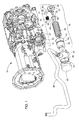
- the gear housing 10 a filter housing 16 in a lower, rear area for an oil, hydraulic fluid filter assembly that Hereinafter referred to as filter assembly 18.
- This filter housing 16 is arranged such that the Filter assembly 18 in the reservoir 12, which in the lower area of the transmission housing 10 is received, is submerged.
- An opening 20 of the filter housing 16 is in the Essentially round and provides cutouts 22 for receiving Screws or similar fasteners 24 are available.
- the filter assembly 18 can be received in the housing 16 be, which in Figures 1 and 2 in a Exploded view is shown.
- Figure 3 a cut-away representation of the filter assembly 18 shown, being arranged on a cast filter head 26.
- the Filter head 26 is detachable by means of the gear housing 10 Screws 24 connected by threaded holes 22 in the Transmission housing 10 are included.
- the filter head 26 is adapted to a screw-on end closure or one Cover 28 to accommodate the filter assembly 18 allow it to be easily installed and cantilevered and manner in the reservoir 12 of the transmission housing 10 to be included.
- the lid 28 allows this Filter assembly 18, quick and easy to remove, so that a new filter assembly 18 can be assembled.
- FIG. 4 in which a Hydraulic system is shown, which one in which Gearbox 10 has arranged reservoir 12. It will a hydraulic pump 30 is provided to Suck hydraulic fluid from the reservoir 12 through which Filter assembly 18 and then pull into the different To move hydraulic system components 14 on the vehicle, before returning to reservoir 12.
- FIGS. 2 and 3 are again considered, from which it can be seen that the filter assembly 18 comprises a filter element 32, which is accommodated in a cartridge 34, a sieve element 36, which is accommodated by the filter element 32, and a bypass valve 38, which in FIG the sieve element 36 is arranged.
- the cartridge 34 is provided with a U-shaped channel 40 in which a diametrical or circumferential O-ring or a sealing element 42 is received. This sealing element 42 serves to establish a liquid-tight connection between the cartridge 34 and the filter head 26 and to position the filter assembly 18 appropriately in the filter head 26.
- the sieve element 36 is attached in an end region of the filter element 32 and has an end wall 44 and an elongated sieve 46.
- the screen 46 takes the form of a small-opening apron with a hollow core.
- a securing ring or securing element 48 is provided at an end region of the sieve element 36. This securing element 48 is preferably pressed into an opening formed by a shoulder 50, which is molded onto the one cartridge cover 52 (see FIGS. 1, 2 and 3a).
- the bypass valve 38 arranged in the sieve element 36 has a spring 54, which is arranged in a spring housing 56 is.
- the spring housing 56 has one at one end region Spring retainer 58 on which the spring 54 abuts.
- the other The end region of the spring 54 abuts a closure element 60, which in turn rests on a seat 62, which on a End region of the spring housing 56 is provided.
- the filter assembly 18 When assembled, the filter assembly 18 is in the Supported filter head 26 and extends in one cantilevered manner in the reservoir 12 in the Transmission housing 10.
- the filter head 26 is on the Gearbox 10 attached by screws 24 to the Filter assembly 18 in the reservoir in the transmission housing 10 to keep in the right position.
- the lid 28 is on the Filter head 26 secured by screwing.
- Another o-ring or a sealing element 64 is provided around the cover 28 to seal against the filter head 26.
- the hydraulic pump 30 serves to Hydraulic fluid from the reservoir 12 in the Gearbox 10 through the filter assembly 18, one Intake pipe 66 along and to the hydraulic pump 30 pull. From the hydraulic pump 30, the hydraulic fluid 12 to the various hydraulic system components 14 and finally back into the reservoir 12 in the gearbox 10 passed where it is then ready to other components of the Serve gear during operation.
- the bypass valve 38 opens and allows the cold hydraulic fluid to flow out of the end portion of the cartridge 34 through the screen member 36, through the hollow core of the filter element 32, and through the suction port 66 to the hydraulic pump 30 .
- the bypass valve 38 acts to direct the hydraulic fluid to the inlet area of the screen member 36 when the hydraulic oil pressure is approximately 5 pounds per square inch (34,474 N / m 2 ) versus vacuum.
- the bypass valve 38 thus serves to allow the cold hydraulic fluid to pass through the sieve element 36 but not through the filter element 32.
- the bypass valve 38 serves to direct the hydraulic fluid through the inlet area of the filter element 32 when the hydraulic fluid pressure is less than 5 pounds per square inch (34,474 N / m 2 ) based on vacuum.
- the screen element 36 is designed such that it filters out impurities in the hydraulic fluid which have a particle size between 60 and 100 micrometers
- the filter element 32 is designed such that it filters out impurities of a size of 5 micrometers and larger ,
- the filter assembly 18 in the gear housing 10 in the Filter housing 16 is provided, the necessary Cable brackets and the space that is needed to the Attaching filter assembly 18 minimized, thereby reducing installation space remains for other vehicle assemblies.
- the screwable, Removable lid 28 allows easy access to the Filter assembly 18 for service and maintenance purposes. Since the Filter assembly 18 in the filter head 27 easily removed and maintenance can be made easier.
- the Arrangement of the filter assembly 18 in the reservoir 12 in the Gearbox 10 ensures that it is in the Hydraulic fluid is submerged and the cavitation and / or an idle of the hydraulic pump due to one Air pulling is reduced.
Landscapes
- Chemical & Material Sciences (AREA)
- Chemical Kinetics & Catalysis (AREA)
- General Details Of Gearings (AREA)
Abstract
Description
- Fig. 1
- eine perspektivische Darstellung eines Getriebegehäuses mit einer Explosionsdarstellung eines Filterzusammenbaus,
- Fig. 2
- eine vergrößerte, perspektivische Darstellung des Filterzusammenbaus,
- Fig. 3
- eine teilweise aufgebrochene Ansicht des Filterzusammenbaus,
- Fig.3a
- eine weitere vergrößerte Darstellung eines Bereichs, in dem ein Umgehungsventil in dem Filterzusammenbau angebracht ist,
- Fig. 4
- eine schematische Darstellung eines Hydrauliksystems mit einem derartigen Filterzusammenbau,
- Fig. 5
- eine Schnittdarstellung des Filterzusammenbaus, die einen Hydraulikstrom durch eine Rückhalteinrichtung und ein Umgehungsventil illustriert und
- Fig. 6
- eine Schnittdarstellung entsprechend Figur 5, die einen Hydraulikstrom durch einen Filter während eines Normalbetriebs verdeutlicht.
Das Siebelement 36 ist in einem Endbereich des Filterelements 32 angebracht und weist eine Endwand 44 und ein längliches Sieb 46 auf. Das Sieb 46 nimmt die Form einer kleine Öffnungen aufweisenden Schürze mit einem hohlen Kern an. An einem Endbereich des Siebelements 36 ist ein Sicherungsring bzw. ein Sicherungselement 48 vorgesehen. Dieses Sicherungselement 48 ist vorzugsweise in eine durch eine Schulter 50 gebildete Öffnung eingepresst, die an den einen Kartuschendeckel 52 angeformt ist (siehe Figuren 1, 2 und 3a).
Claims (14)
- Filterzusammenbau (18), vorzugsweise ein Einwegfilterzusammenbau, mit einem Filterelement (32) mit einem Einlassbereich und einem Auslassbereich, einem Siebelement (36) mit einem Einlassbereich, der wirksam mit dem Einlass des Filterelements, und einem Auslassbereich der wirksam mit dem Auslassbereich des Filterelements verbunden ist, und mit einem Umgehungsventil (38), dadurch gekennzeichnet, dass das Siebelement (36) im Innern des Filterelement (32) angeordnet ist und das Umgehungsventil (38) entweder einen Hydraulikfluss durch das Filterelement (32) oder durch das Siebelement (36) erlaubt.
- Filterzusammenbau nach Anspruch 1, dass das Umgehungsventil (38) druckabhängig bzw. in der Art eines druckgesteuerten Ventils ausgebildet ist.
- Filterzusammenbau nach Anspruch 1 oder 2, dadurch gekennzeichnet, dass das Umgehungsventil Hydraulikflüssigkeit zu dem Einlassbereich des Siebelements (36) leitet, wenn ein bestimmter Hydraulikflüssigkeitsdruck erreicht ist bzw. überstiegen wird bzw. Hydraulikflüssigkeit zu dem Einlassbereich des Filterelements (32) leitet, wenn ein bestimmter Hydraulikflüssigkeitsdruck unterschritten wird bzw. solange er ein bestimmter Hydraulikflüssigkeitsdruck nicht erreicht wird.
- Filterzusammenbau nach einem oder mehreren der vorherigen Ansprüche, dadurch gekennzeichnet, dass das Siebelement (36) an den Einlassbereich des Filterelements (32) angrenzt bzw. in diesem angeordnet ist.
- Filterzusammenbau nach einem oder mehreren der vorherigen Ansprüche, dadurch gekennzeichnet, dass es im Wesentlichen in der Art einer zylindrischen Schürze mit einem hohlen, zentralen Kern ausgebildet ist, wobei der Kern gegenüberliegende erste und zweite Endbereiche aufweist und wobei der erste Endbereich als ein Einlassbereich des Filterelements (32) ausgebildet ist.
- Filterzusammenbau nach einem oder mehreren der vorherigen Ansprüche, dadurch gekennzeichnet, dass das Siebelement (36) zumindest teilweise oder vollständig in dem zweiten Endbereich des Filterelements (32) aufgenommen wird und/oder das Umgehungsventil (38) zumindest teilweise oder vollständig in dem Einlassbereich des Siebelements (36) aufgenommen wird.
- Getriebegehäuse (10) mit einem unteren und einem oberen Bereich, einem Reservoir (12) für Hydraulikflüssigkeit, das in dem unteren Bereich angeordnet ist, einer Hydraulikpumpe (30), einem Filtergehäuse (16), das in dem unteren Bereich angeordnet ist und mit dem Reservoir (12) in Verbindung steht und eine Öffnung (20) aufweist, und mit einem Filterzusammenbau (18), insbesondere nach einem oder mehreren der vorherigen Ansprüche, welcher durch die Öffnung (20) in das Filtergehäuse eingebracht werden kann und welcher ein Filterelement (32) mit einem Einlassbereich und einem Auslassbereich, ein Siebelement (36) und ein Umgehungsventil (38) aufweist, dadurch gekennzeichnet, dass das Siebelement (36) im Innern des Filterelements (32) angeordnet ist und das Umgehungsventil (38) entweder einen Hydraulikfluss durch das Filterelement (32) oder durch das Siebelement (36) erlaubt.
- Getriebegehäuse nach Anspruch 7, dadurch gekennzeichnet, dass der Filterzusammenbau (18) in einem Filterkopf (26) mit einem entfernbaren Deck (28) angeordnet ist.
- Getriebegehäuse nach Anspruch 8, dadurch gekennzeichnet, dass der Deckel (28) auf den Filterkopf (26) aufschraubbar ist.
- Getriebegehäuse nach Anspruch 8 oder 39, dadurch gekennzeichnet, dass der Filterkopf (26) mit dem Getriebegehäuse (10) lösbar verbunden bzw. verschraubt ist.
- Getriebegehäuse nach einem oder mehreren der Ansprüche 7 bis 10, dadurch gekennzeichnet, dass das Umgehungsventil (38) druckabhängig bzw. in der Art eines druckgesteuerten Ventils ausgebildet ist.
- Getriebegehäuse nach einem oder mehreren der Ansprüche 7 bis 11, dadurch gekennzeichnet, dass der Filterzusammenbau (18) in der Art eines Einweg- bzw. Wegwerfelements ausgebildet ist.
- Getriebegehäuse nach einem oder mehreren der Ansprüche 7 bis 12, dadurch gekennzeichnet, dass der Filterzusammenbau (18) verbrennbar ist.
- Fahrzeug, insbesondere ein Kompaktfahrzeug, mit einem Getriebegehäuse (10) nach einem oder mehreren der Ansprüche 7 bis 13.
Applications Claiming Priority (4)
| Application Number | Priority Date | Filing Date | Title |
|---|---|---|---|
| US10/372,753 US7056432B2 (en) | 2003-02-21 | 2003-02-21 | Tank mounted oil filter assembly |
| US372602 | 2003-02-21 | ||
| US10/372,602 US7166210B2 (en) | 2003-02-21 | 2003-02-21 | Oil filter cartridge |
| US372753 | 2003-02-21 |
Publications (3)
| Publication Number | Publication Date |
|---|---|
| EP1449572A2 true EP1449572A2 (de) | 2004-08-25 |
| EP1449572A3 EP1449572A3 (de) | 2004-10-20 |
| EP1449572B1 EP1449572B1 (de) | 2008-07-30 |
Family
ID=32737999
Family Applications (1)
| Application Number | Title | Priority Date | Filing Date |
|---|---|---|---|
| EP04100680A Expired - Lifetime EP1449572B1 (de) | 2003-02-21 | 2004-02-20 | Getriebegehäuse und Fahrzeug |
Country Status (2)
| Country | Link |
|---|---|
| EP (1) | EP1449572B1 (de) |
| DE (1) | DE502004007708D1 (de) |
Cited By (2)
| Publication number | Priority date | Publication date | Assignee | Title |
|---|---|---|---|---|
| EP2926880A1 (de) * | 2014-04-03 | 2015-10-07 | Schaeffler Technologies GmbH & Co. KG | Filtereinheit für ein hydraulisches System |
| WO2021002291A1 (ja) * | 2019-07-03 | 2021-01-07 | ヤマシンフィルタ株式会社 | タンク装置 |
Families Citing this family (1)
| Publication number | Priority date | Publication date | Assignee | Title |
|---|---|---|---|---|
| JP6206300B2 (ja) * | 2014-04-04 | 2017-10-04 | スズキ株式会社 | 動力伝達装置 |
Family Cites Families (6)
| Publication number | Priority date | Publication date | Assignee | Title |
|---|---|---|---|---|
| US3469697A (en) * | 1966-12-14 | 1969-09-30 | Marvel Eng Co | Filter and by-pass valve assembly |
| DE4030097A1 (de) * | 1990-09-22 | 1992-03-26 | Deere & Co | Getriebegehaeuse aus gussmetall |
| JPH10252432A (ja) * | 1997-03-06 | 1998-09-22 | Yamaha Motor Co Ltd | エンジンの潤滑装置 |
| JP3243640B2 (ja) * | 1998-02-20 | 2002-01-07 | 株式会社テネックス | エレメント交換型オイルフィルタのドレイン構造 |
| WO2002032543A1 (de) * | 2000-10-18 | 2002-04-25 | Argo Gmbh Für Fluidtechnik | Filtervorrichtung |
| DE10113179C2 (de) * | 2001-03-19 | 2003-12-11 | Rt Filtertechnik Gmbh | Filter |
-
2004
- 2004-02-20 EP EP04100680A patent/EP1449572B1/de not_active Expired - Lifetime
- 2004-02-20 DE DE502004007708T patent/DE502004007708D1/de not_active Expired - Lifetime
Cited By (5)
| Publication number | Priority date | Publication date | Assignee | Title |
|---|---|---|---|---|
| EP2926880A1 (de) * | 2014-04-03 | 2015-10-07 | Schaeffler Technologies GmbH & Co. KG | Filtereinheit für ein hydraulisches System |
| WO2021002291A1 (ja) * | 2019-07-03 | 2021-01-07 | ヤマシンフィルタ株式会社 | タンク装置 |
| JP2021010854A (ja) * | 2019-07-03 | 2021-02-04 | ヤマシンフィルタ株式会社 | タンク装置 |
| JP7262325B2 (ja) | 2019-07-03 | 2023-04-21 | ヤマシンフィルタ株式会社 | タンク装置 |
| US12025085B2 (en) | 2019-07-03 | 2024-07-02 | Yamashin-Filter Corp. | Tank device |
Also Published As
| Publication number | Publication date |
|---|---|
| EP1449572B1 (de) | 2008-07-30 |
| EP1449572A3 (de) | 2004-10-20 |
| DE502004007708D1 (de) | 2008-09-11 |
Similar Documents
| Publication | Publication Date | Title |
|---|---|---|
| DE2436080C3 (de) | Vorrichtung zum Abtrennen von öl von Wasser und Feststoffteilchen | |
| DE112009000563B4 (de) | Flüssigkeitsfiltervorrichtung mit Standrohr mit integriertem Regelventil und Verfahren mit dieser Flüssigkeitsfiltervorrichtung | |
| DE19716085B4 (de) | Filter, insbesondere für Kraftstoffe von Verbrennungsmotoren | |
| EP3004620B1 (de) | Filterelement | |
| EP2762219B1 (de) | Becherförmiges Gehäuse und Vorrichtung zum Abscheiden von Flüssigkeit aus Luft | |
| DE69733932T2 (de) | In-situ zu reinigender Filter mit Filter für ein Reinigungsmittel | |
| DE69504105T2 (de) | Zentrifugalreiniger für im kreislauf geführte flüssigkeiten | |
| WO2001007141A1 (de) | Filter für kraftstoffe von verbrennungsmotoren | |
| EP1216740A1 (de) | Filteranordnung für Flüssigkeiten | |
| DE2736153C3 (de) | Filter- und Mischeinrichtung zur Vermischung von Schmieröl und Kraftstoff | |
| DE102006029107B4 (de) | Filteranordnung mit einem Filtergehäuse und mit einem zylindrischen Filterelement | |
| DE202013011849U1 (de) | Filterelement | |
| DE102013020539A1 (de) | Filterelement | |
| WO2011039020A1 (de) | Druckfiltereinrichtung | |
| DE69303447T2 (de) | Vakuumpumpgerät | |
| DE102009030500B4 (de) | Flüssigkeitsfiltersystem eines Flüssigkeitskreislaufs | |
| DE10343555A1 (de) | Brennstofffilteranordnung und Verfahren zum Wechsel eines Brennstofffilters in einem Brennstoffsystem | |
| EP1449572B1 (de) | Getriebegehäuse und Fahrzeug | |
| DE102022102039A1 (de) | Filtervorrichtung zum Filtern eines Fluids, Verwendung eines Filterelements in einer Filtervorrichtung, und Verfahren zum Austausch eines Filterelements | |
| DE102004061874B4 (de) | Kraftstoffpumpenmodul | |
| DE19955636C2 (de) | Saugölfilter für Motoren oder Getriebe oder Automatikgetriebe | |
| DE102006023379A1 (de) | Flüssigkeitspumpe | |
| DE9408687U1 (de) | Kraftstoffilter, insbesondere für Dieselkraftstoff | |
| DE10110381B4 (de) | Vorrichtung zum Abtrennen von Verunreinigungen aus einem Schmieröl einer Brennkraftmaschine | |
| DE102016011395A1 (de) | Schraubenkompressor für ein Nutzfahrzeug |
Legal Events
| Date | Code | Title | Description |
|---|---|---|---|
| PUAI | Public reference made under article 153(3) epc to a published international application that has entered the european phase |
Free format text: ORIGINAL CODE: 0009012 |
|
| AK | Designated contracting states |
Kind code of ref document: A2 Designated state(s): AT BE BG CH CY CZ DE DK EE ES FI FR GB GR HU IE IT LI LU MC NL PT RO SE SI SK TR |
|
| AX | Request for extension of the european patent |
Extension state: AL LT LV MK |
|
| PUAL | Search report despatched |
Free format text: ORIGINAL CODE: 0009013 |
|
| AK | Designated contracting states |
Kind code of ref document: A3 Designated state(s): AT BE BG CH CY CZ DE DK EE ES FI FR GB GR HU IE IT LI LU MC NL PT RO SE SI SK TR |
|
| AX | Request for extension of the european patent |
Extension state: AL LT LV MK |
|
| RTI1 | Title (correction) |
Free format text: FILTER ASSEMBLY, GEARBOX CASING AND VEHICLE |
|
| 17P | Request for examination filed |
Effective date: 20050420 |
|
| AKX | Designation fees paid |
Designated state(s): DE ES FI GB IT |
|
| 17Q | First examination report despatched |
Effective date: 20060330 |
|
| GRAP | Despatch of communication of intention to grant a patent |
Free format text: ORIGINAL CODE: EPIDOSNIGR1 |
|
| RTI1 | Title (correction) |
Free format text: GEARBOX CASING AND VEHICLE |
|
| GRAS | Grant fee paid |
Free format text: ORIGINAL CODE: EPIDOSNIGR3 |
|
| GRAA | (expected) grant |
Free format text: ORIGINAL CODE: 0009210 |
|
| AK | Designated contracting states |
Kind code of ref document: B1 Designated state(s): DE ES FI GB IT |
|
| REG | Reference to a national code |
Ref country code: GB Ref legal event code: FG4D Free format text: NOT ENGLISH |
|
| REF | Corresponds to: |
Ref document number: 502004007708 Country of ref document: DE Date of ref document: 20080911 Kind code of ref document: P |
|
| PG25 | Lapsed in a contracting state [announced via postgrant information from national office to epo] |
Ref country code: ES Free format text: LAPSE BECAUSE OF FAILURE TO SUBMIT A TRANSLATION OF THE DESCRIPTION OR TO PAY THE FEE WITHIN THE PRESCRIBED TIME-LIMIT Effective date: 20081110 |
|
| PG25 | Lapsed in a contracting state [announced via postgrant information from national office to epo] |
Ref country code: FI Free format text: LAPSE BECAUSE OF FAILURE TO SUBMIT A TRANSLATION OF THE DESCRIPTION OR TO PAY THE FEE WITHIN THE PRESCRIBED TIME-LIMIT Effective date: 20080730 |
|
| PLBE | No opposition filed within time limit |
Free format text: ORIGINAL CODE: 0009261 |
|
| STAA | Information on the status of an ep patent application or granted ep patent |
Free format text: STATUS: NO OPPOSITION FILED WITHIN TIME LIMIT |
|
| 26N | No opposition filed |
Effective date: 20090506 |
|
| PG25 | Lapsed in a contracting state [announced via postgrant information from national office to epo] |
Ref country code: IT Free format text: LAPSE BECAUSE OF NON-PAYMENT OF DUE FEES Effective date: 20090220 |
|
| PGFP | Annual fee paid to national office [announced via postgrant information from national office to epo] |
Ref country code: DE Payment date: 20160226 Year of fee payment: 13 |
|
| REG | Reference to a national code |
Ref country code: DE Ref legal event code: R119 Ref document number: 502004007708 Country of ref document: DE |
|
| PG25 | Lapsed in a contracting state [announced via postgrant information from national office to epo] |
Ref country code: DE Free format text: LAPSE BECAUSE OF NON-PAYMENT OF DUE FEES Effective date: 20170901 |
|
| PGFP | Annual fee paid to national office [announced via postgrant information from national office to epo] |
Ref country code: GB Payment date: 20200227 Year of fee payment: 17 |
|
| GBPC | Gb: european patent ceased through non-payment of renewal fee |
Effective date: 20210220 |
|
| PG25 | Lapsed in a contracting state [announced via postgrant information from national office to epo] |
Ref country code: GB Free format text: LAPSE BECAUSE OF NON-PAYMENT OF DUE FEES Effective date: 20210220 |