EP1449478B1 - Sytème à poches comprenant un moyen d'association de récipients d'échantillonnage - Google Patents
Sytème à poches comprenant un moyen d'association de récipients d'échantillonnage Download PDFInfo
- Publication number
- EP1449478B1 EP1449478B1 EP20040290221 EP04290221A EP1449478B1 EP 1449478 B1 EP1449478 B1 EP 1449478B1 EP 20040290221 EP20040290221 EP 20040290221 EP 04290221 A EP04290221 A EP 04290221A EP 1449478 B1 EP1449478 B1 EP 1449478B1
- Authority
- EP
- European Patent Office
- Prior art keywords
- container
- guide
- containers
- bag
- sampling
- Prior art date
- Legal status (The legal status is an assumption and is not a legal conclusion. Google has not performed a legal analysis and makes no representation as to the accuracy of the status listed.)
- Expired - Lifetime
Links
- 239000000523 sample Substances 0.000 title 1
- 210000004369 blood Anatomy 0.000 claims abstract description 25
- 239000008280 blood Substances 0.000 claims abstract description 25
- 239000012530 fluid Substances 0.000 claims abstract description 19
- 239000013060 biological fluid Substances 0.000 claims abstract description 6
- 238000005070 sampling Methods 0.000 claims description 45
- 238000011144 upstream manufacturing Methods 0.000 claims description 5
- 230000003993 interaction Effects 0.000 claims description 2
- 230000002441 reversible effect Effects 0.000 claims description 2
- 238000010241 blood sampling Methods 0.000 abstract description 3
- 230000017531 blood circulation Effects 0.000 abstract 3
- 238000000605 extraction Methods 0.000 abstract 2
- 238000004519 manufacturing process Methods 0.000 description 4
- 238000011109 contamination Methods 0.000 description 2
- 238000000926 separation method Methods 0.000 description 2
- 241000894006 Bacteria Species 0.000 description 1
- 239000000853 adhesive Substances 0.000 description 1
- 239000012503 blood component Substances 0.000 description 1
- 239000000470 constituent Substances 0.000 description 1
- 238000010494 dissociation reaction Methods 0.000 description 1
- 230000005593 dissociations Effects 0.000 description 1
- 230000000694 effects Effects 0.000 description 1
- 238000001914 filtration Methods 0.000 description 1
- 238000005534 hematocrit Methods 0.000 description 1
- 210000000265 leukocyte Anatomy 0.000 description 1
- 230000001012 protector Effects 0.000 description 1
- 239000000126 substance Substances 0.000 description 1
- 210000003462 vein Anatomy 0.000 description 1
- 239000002699 waste material Substances 0.000 description 1
- 238000003466 welding Methods 0.000 description 1
Images


Classifications
-
- A—HUMAN NECESSITIES
- A61—MEDICAL OR VETERINARY SCIENCE; HYGIENE
- A61M—DEVICES FOR INTRODUCING MEDIA INTO, OR ONTO, THE BODY; DEVICES FOR TRANSDUCING BODY MEDIA OR FOR TAKING MEDIA FROM THE BODY; DEVICES FOR PRODUCING OR ENDING SLEEP OR STUPOR
- A61M1/00—Suction or pumping devices for medical purposes; Devices for carrying-off, for treatment of, or for carrying-over, body-liquids; Drainage systems
- A61M1/02—Blood transfusion apparatus
- A61M1/0209—Multiple bag systems for separating or storing blood components
-
- A—HUMAN NECESSITIES
- A61—MEDICAL OR VETERINARY SCIENCE; HYGIENE
- A61B—DIAGNOSIS; SURGERY; IDENTIFICATION
- A61B5/00—Measuring for diagnostic purposes; Identification of persons
- A61B5/15—Devices for taking samples of blood
- A61B5/150007—Details
- A61B5/150015—Source of blood
- A61B5/15003—Source of blood for venous or arterial blood
-
- A—HUMAN NECESSITIES
- A61—MEDICAL OR VETERINARY SCIENCE; HYGIENE
- A61B—DIAGNOSIS; SURGERY; IDENTIFICATION
- A61B5/00—Measuring for diagnostic purposes; Identification of persons
- A61B5/15—Devices for taking samples of blood
- A61B5/150007—Details
- A61B5/150206—Construction or design features not otherwise provided for; manufacturing or production; packages; sterilisation of piercing element, piercing device or sampling device
- A61B5/150305—Packages specially adapted for piercing devices or blood sampling devices
-
- A—HUMAN NECESSITIES
- A61—MEDICAL OR VETERINARY SCIENCE; HYGIENE
- A61B—DIAGNOSIS; SURGERY; IDENTIFICATION
- A61B5/00—Measuring for diagnostic purposes; Identification of persons
- A61B5/15—Devices for taking samples of blood
- A61B5/150007—Details
- A61B5/150351—Caps, stoppers or lids for sealing or closing a blood collection vessel or container, e.g. a test-tube or syringe barrel
-
- A—HUMAN NECESSITIES
- A61—MEDICAL OR VETERINARY SCIENCE; HYGIENE
- A61B—DIAGNOSIS; SURGERY; IDENTIFICATION
- A61B5/00—Measuring for diagnostic purposes; Identification of persons
- A61B5/15—Devices for taking samples of blood
- A61B5/150007—Details
- A61B5/150366—Blood collection bags, e.g. connected to the patient by a catheter comprising means for removing a small sample of collected blood from the bag
-
- A—HUMAN NECESSITIES
- A61—MEDICAL OR VETERINARY SCIENCE; HYGIENE
- A61B—DIAGNOSIS; SURGERY; IDENTIFICATION
- A61B5/00—Measuring for diagnostic purposes; Identification of persons
- A61B5/15—Devices for taking samples of blood
- A61B5/150007—Details
- A61B5/150374—Details of piercing elements or protective means for preventing accidental injuries by such piercing elements
- A61B5/150381—Design of piercing elements
- A61B5/150389—Hollow piercing elements, e.g. canulas, needles, for piercing the skin
-
- A—HUMAN NECESSITIES
- A61—MEDICAL OR VETERINARY SCIENCE; HYGIENE
- A61B—DIAGNOSIS; SURGERY; IDENTIFICATION
- A61B5/00—Measuring for diagnostic purposes; Identification of persons
- A61B5/15—Devices for taking samples of blood
- A61B5/150007—Details
- A61B5/150374—Details of piercing elements or protective means for preventing accidental injuries by such piercing elements
- A61B5/150381—Design of piercing elements
- A61B5/150503—Single-ended needles
-
- A—HUMAN NECESSITIES
- A61—MEDICAL OR VETERINARY SCIENCE; HYGIENE
- A61B—DIAGNOSIS; SURGERY; IDENTIFICATION
- A61B5/00—Measuring for diagnostic purposes; Identification of persons
- A61B5/15—Devices for taking samples of blood
- A61B5/150007—Details
- A61B5/150374—Details of piercing elements or protective means for preventing accidental injuries by such piercing elements
- A61B5/150534—Design of protective means for piercing elements for preventing accidental needle sticks, e.g. shields, caps, protectors, axially extensible sleeves, pivotable protective sleeves
- A61B5/150572—Pierceable protectors, e.g. shields, caps, sleeves or films, e.g. for hygienic purposes
-
- A—HUMAN NECESSITIES
- A61—MEDICAL OR VETERINARY SCIENCE; HYGIENE
- A61B—DIAGNOSIS; SURGERY; IDENTIFICATION
- A61B5/00—Measuring for diagnostic purposes; Identification of persons
- A61B5/15—Devices for taking samples of blood
- A61B5/150007—Details
- A61B5/150374—Details of piercing elements or protective means for preventing accidental injuries by such piercing elements
- A61B5/150534—Design of protective means for piercing elements for preventing accidental needle sticks, e.g. shields, caps, protectors, axially extensible sleeves, pivotable protective sleeves
- A61B5/150694—Procedure for removing protection means at the time of piercing
- A61B5/150717—Procedure for removing protection means at the time of piercing manually removed
-
- A—HUMAN NECESSITIES
- A61—MEDICAL OR VETERINARY SCIENCE; HYGIENE
- A61B—DIAGNOSIS; SURGERY; IDENTIFICATION
- A61B5/00—Measuring for diagnostic purposes; Identification of persons
- A61B5/15—Devices for taking samples of blood
- A61B5/150007—Details
- A61B5/150732—Needle holders, for instance for holding the needle by the hub, used for example with double-ended needle and pre-evacuated tube
-
- A—HUMAN NECESSITIES
- A61—MEDICAL OR VETERINARY SCIENCE; HYGIENE
- A61B—DIAGNOSIS; SURGERY; IDENTIFICATION
- A61B5/00—Measuring for diagnostic purposes; Identification of persons
- A61B5/15—Devices for taking samples of blood
- A61B5/150007—Details
- A61B5/150763—Details with identification means
- A61B5/150786—Optical identification systems, e.g. bar codes, colour codes
-
- A—HUMAN NECESSITIES
- A61—MEDICAL OR VETERINARY SCIENCE; HYGIENE
- A61B—DIAGNOSIS; SURGERY; IDENTIFICATION
- A61B5/00—Measuring for diagnostic purposes; Identification of persons
- A61B5/15—Devices for taking samples of blood
- A61B5/150007—Details
- A61B5/150801—Means for facilitating use, e.g. by people with impaired vision; means for indicating when used correctly or incorrectly; means for alarming
- A61B5/150824—Means for facilitating use, e.g. by people with impaired vision; means for indicating when used correctly or incorrectly; means for alarming by visual feedback
-
- A—HUMAN NECESSITIES
- A61—MEDICAL OR VETERINARY SCIENCE; HYGIENE
- A61B—DIAGNOSIS; SURGERY; IDENTIFICATION
- A61B5/00—Measuring for diagnostic purposes; Identification of persons
- A61B5/15—Devices for taking samples of blood
- A61B5/150992—Blood sampling from a fluid line external to a patient, such as a catheter line, combined with an infusion line; Blood sampling from indwelling needle sets, e.g. sealable ports, luer couplings or valves
-
- A—HUMAN NECESSITIES
- A61—MEDICAL OR VETERINARY SCIENCE; HYGIENE
- A61B—DIAGNOSIS; SURGERY; IDENTIFICATION
- A61B5/00—Measuring for diagnostic purposes; Identification of persons
- A61B5/15—Devices for taking samples of blood
- A61B5/153—Devices specially adapted for taking samples of venous or arterial blood, e.g. with syringes
- A61B5/154—Devices using pre-evacuated means
-
- A—HUMAN NECESSITIES
- A61—MEDICAL OR VETERINARY SCIENCE; HYGIENE
- A61M—DEVICES FOR INTRODUCING MEDIA INTO, OR ONTO, THE BODY; DEVICES FOR TRANSDUCING BODY MEDIA OR FOR TAKING MEDIA FROM THE BODY; DEVICES FOR PRODUCING OR ENDING SLEEP OR STUPOR
- A61M1/00—Suction or pumping devices for medical purposes; Devices for carrying-off, for treatment of, or for carrying-over, body-liquids; Drainage systems
- A61M1/02—Blood transfusion apparatus
- A61M1/0209—Multiple bag systems for separating or storing blood components
- A61M1/0218—Multiple bag systems for separating or storing blood components with filters
-
- A—HUMAN NECESSITIES
- A61—MEDICAL OR VETERINARY SCIENCE; HYGIENE
- A61M—DEVICES FOR INTRODUCING MEDIA INTO, OR ONTO, THE BODY; DEVICES FOR TRANSDUCING BODY MEDIA OR FOR TAKING MEDIA FROM THE BODY; DEVICES FOR PRODUCING OR ENDING SLEEP OR STUPOR
- A61M1/00—Suction or pumping devices for medical purposes; Devices for carrying-off, for treatment of, or for carrying-over, body-liquids; Drainage systems
- A61M1/02—Blood transfusion apparatus
- A61M1/0209—Multiple bag systems for separating or storing blood components
- A61M1/0236—Multiple bag systems for separating or storing blood components with sampling means, e.g. sample bag or sampling port
-
- A—HUMAN NECESSITIES
- A61—MEDICAL OR VETERINARY SCIENCE; HYGIENE
- A61J—CONTAINERS SPECIALLY ADAPTED FOR MEDICAL OR PHARMACEUTICAL PURPOSES; DEVICES OR METHODS SPECIALLY ADAPTED FOR BRINGING PHARMACEUTICAL PRODUCTS INTO PARTICULAR PHYSICAL OR ADMINISTERING FORMS; DEVICES FOR ADMINISTERING FOOD OR MEDICINES ORALLY; BABY COMFORTERS; DEVICES FOR RECEIVING SPITTLE
- A61J1/00—Containers specially adapted for medical or pharmaceutical purposes
- A61J1/05—Containers specially adapted for medical or pharmaceutical purposes for collecting, storing or administering blood, plasma or medical fluids ; Infusion or perfusion containers
- A61J1/10—Bag-type containers
- A61J1/12—Bag-type containers with means for holding samples of contents
-
- A—HUMAN NECESSITIES
- A61—MEDICAL OR VETERINARY SCIENCE; HYGIENE
- A61J—CONTAINERS SPECIALLY ADAPTED FOR MEDICAL OR PHARMACEUTICAL PURPOSES; DEVICES OR METHODS SPECIALLY ADAPTED FOR BRINGING PHARMACEUTICAL PRODUCTS INTO PARTICULAR PHYSICAL OR ADMINISTERING FORMS; DEVICES FOR ADMINISTERING FOOD OR MEDICINES ORALLY; BABY COMFORTERS; DEVICES FOR RECEIVING SPITTLE
- A61J2205/00—General identification or selection means
- A61J2205/10—Bar codes
-
- A—HUMAN NECESSITIES
- A61—MEDICAL OR VETERINARY SCIENCE; HYGIENE
- A61J—CONTAINERS SPECIALLY ADAPTED FOR MEDICAL OR PHARMACEUTICAL PURPOSES; DEVICES OR METHODS SPECIALLY ADAPTED FOR BRINGING PHARMACEUTICAL PRODUCTS INTO PARTICULAR PHYSICAL OR ADMINISTERING FORMS; DEVICES FOR ADMINISTERING FOOD OR MEDICINES ORALLY; BABY COMFORTERS; DEVICES FOR RECEIVING SPITTLE
- A61J2205/00—General identification or selection means
- A61J2205/30—Printed labels
-
- Y—GENERAL TAGGING OF NEW TECHNOLOGICAL DEVELOPMENTS; GENERAL TAGGING OF CROSS-SECTIONAL TECHNOLOGIES SPANNING OVER SEVERAL SECTIONS OF THE IPC; TECHNICAL SUBJECTS COVERED BY FORMER USPC CROSS-REFERENCE ART COLLECTIONS [XRACs] AND DIGESTS
- Y10—TECHNICAL SUBJECTS COVERED BY FORMER USPC
- Y10T—TECHNICAL SUBJECTS COVERED BY FORMER US CLASSIFICATION
- Y10T137/00—Fluid handling
- Y10T137/2713—Siphons
- Y10T137/272—Plural
- Y10T137/2733—Sequentially discharging in parallel
-
- Y—GENERAL TAGGING OF NEW TECHNOLOGICAL DEVELOPMENTS; GENERAL TAGGING OF CROSS-SECTIONAL TECHNOLOGIES SPANNING OVER SEVERAL SECTIONS OF THE IPC; TECHNICAL SUBJECTS COVERED BY FORMER USPC CROSS-REFERENCE ART COLLECTIONS [XRACs] AND DIGESTS
- Y10—TECHNICAL SUBJECTS COVERED BY FORMER USPC
- Y10T—TECHNICAL SUBJECTS COVERED BY FORMER US CLASSIFICATION
- Y10T137/00—Fluid handling
- Y10T137/4673—Plural tanks or compartments with parallel flow
- Y10T137/469—Sequentially filled and emptied [e.g., holding type]
-
- Y—GENERAL TAGGING OF NEW TECHNOLOGICAL DEVELOPMENTS; GENERAL TAGGING OF CROSS-SECTIONAL TECHNOLOGIES SPANNING OVER SEVERAL SECTIONS OF THE IPC; TECHNICAL SUBJECTS COVERED BY FORMER USPC CROSS-REFERENCE ART COLLECTIONS [XRACs] AND DIGESTS
- Y10—TECHNICAL SUBJECTS COVERED BY FORMER USPC
- Y10T—TECHNICAL SUBJECTS COVERED BY FORMER US CLASSIFICATION
- Y10T137/00—Fluid handling
- Y10T137/4673—Plural tanks or compartments with parallel flow
- Y10T137/469—Sequentially filled and emptied [e.g., holding type]
- Y10T137/4707—With relative rotation of tank group and filling head
Definitions
- the invention relates to a bag system for the collection of a biological fluid.
- the bag system includes, in a closed circuit, a blood collection device which is in fluid communication with at least one blood collection bag.
- the system includes a blood sampling device for receiving a portion of the blood drawn, said device comprising at least one sampling vessel.
- sampling device makes it possible to obtain, in each container, a blood sample to be analyzed, in particular to perform serology, virology and counting.
- the bag system can be used by taking the first few milliliters of blood in the sampling device, which has a number of advantages.
- the loss of blood volume for the donor being compensated by the plasma intake the hematocrit of the blood to be analyzed would be lower if the sampling device was filled after the collection bag, and by therefore the count would be skewed.
- the object of the invention is in particular to solve this problem by proposing a bag system in which each sample container is stored at the level of the fluid transfer means from the bag system therein, which container can then be guided. by the operator in the transfer means for taking the sample.
- the invention relates to a bag system for the collection of a biological fluid, as defined in claim 1.
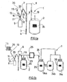
- the Figures 1a and 1b represent a bag system 1 comprising means for sampling the fluid from a donor and at least one collection bag 2 for receiving the fluid taken, in particular blood.
- the sampling means consist in particular of a needle 3 allowing access to the vein of the donor and a cap 4 protecting the needle 3.
- a needle protector 5 can be placed in a sliding manner on a needle.
- the bag system 1 further comprises a sampling device, which is in fluid communication with the collection bag 2 via the first 6 and a second pipe 7 connected at a first connector 8 in the form of a three-way junction.
- the sampling device comprises a sampling bag 9 which is connected to the downstream end of the second tubing 7.
- the terms downstream and upstream are defined with respect to the direction of flow of the blood, the bag sampling device and sampling device.
- the sampling device further comprises a fluid transfer means 10, which is in fluid communication with the collection bag 2 via the first 6 and second tubing 7, and optionally a third tubing 11 connected to the second pipe 7 at a second connector 12 in the form of a three-way junction.
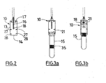
- the transfer means 10 comprises a hollow guide 13, open at the front part 14 to allow the introduction of a sampling container 15, and a hollow needle 16 passing through the rear portion 17 of the guide, so that a the downstream portion of said needle extends inside the guide and an upstream portion of said needle 16 extends outside the guide.
- the downstream segment of the hollow needle 16 is enclosed in an elastic sleeve 18.
- the upstream segment of the hollow needle 16 allows the connection of the transfer means with the bag system 1.
- a fluidic communication means or tubular is then connected. on said upstream segment.
- a first 19 and a second clamp 20 may be located respectively on the first pipe 6, downstream of the connector 8, and on the second pipe 7.
- the clamps 19, 20 can direct the flow of fluid taken, or to the pocket sampling 9, the first clamp 19 is closed while the second clamp 20 is open, either to the collection bag 2, the second clamp 20 is closed while the first clamp 19 is open.
- the sampling container 15 is filled with the collected blood contained in the sample bag 9, when said container 15 is placed in the transfer position, namely when the downstream end of the needle 16 is in fluid communication with inside the container 15, by perforation of a closure element 21 of the container 15.
- Openers may be provided within the bag system 1.
- a circuit breaker 22 may be located on the second tubing 7 near the first connector 8.
- the collection bag 2 can be in fluid communication, via a fourth tube 23, with satellite bags 24a-c .
- a leucocyte filter 25 is located between the collection bag 2 and a satellite bag 24a.
- the satellite pocket 24a may be in fluid communication with one or more other satellite pockets, for example the satellite pocket 24a may be in fluid communication with two other satellite pockets 24b, c.
- a clamp 26 may be provided on the fourth tubing 23 between the collection bag 2 and the filter 25 to leucocyte.
- the satellite bags 24a-c may be provided with identification means 35.
- the transfer means 10 is provided with means for associating the sampling container, as shown in FIG. figure 2 .
- the association means comprises a first 27 and a second 28 set of projections distributed longitudinally on the inner surface of the guide 13, respectively close to the needle 16 of the guide and near the front portion 14 of the guide 13.
- the projections are arranged to be deformable by sliding the container 15 inside the guide 13 so as to allow a reversible association of the container 15 inside the guide 13, and a sliding of the container 15 inside the guide 13 between a waiting position ( figure 3a ), away from the needle 16, and the transfer position ( figure 3b ).
- the projections are flexible, in particular elastic, and are deformable reversibly from a position inclined forward towards a position inclined rearwardly by contacting the container 15 during its sliding inside the guide 13 in the forward direction. back.
- the projections tilt back and forth such that the container is not dissociated from its closure member 21.
- the sampling container comprises a closure member 21 whose diameter is greater than that of the body of the container 15, it is during the passage of the closure member 21 that the projections tilt in one direction or the other.
- the projections of the first set 27 located near the needle 16 are breakable under the effect of the sliding of the container 15 placed in the transfer position.
- the perforation of the closure member 21 is thus visible, the user can verify that the perforation has not occurred prior to taking samples.
- the association means is arranged to allow the support of several containers 15 at a distance from the guide 13 in a waiting position and their sequential guidance in the guide 13, as shown in FIGS. figures 1b and 5a to 5e .
- association means and the transfer means 10 are associated by clipping, by welding, or can be molded in one and the same piece.
- the association means comprises a housing 29 associated with the guide 13.
- Said housing 29 is provided with a skirt 30 in which the closing element 21 of the containers 15 is introduced to allow the longitudinal sliding of the containers 15 in the housing 29 towards the guide 13.
- the inner wall of said skirt 30 is provided with a projection 31 intended, by interaction with the closure elements 21, to prevent transverse shrinkage of the containers 15 of the housing 29.
- the skirt 30 comprises an open end disposed facing a notch formed in the guide, and an opposite end closed. In the other axis, a first open end is disposed facing another end which is open such that the body of the container or containers extends beyond the housing 29.
- the sampling containers are introduced into the guide 13 through its front portion 14 open so that the closure member 21 is at the height of the groove 32 of the housing 29 so that it can be slipped into it.
- a cap 33 is then placed on the guide 13 for holding the containers 15 in the housing 29 until the sampling by the user of the system 1.
- the housing can be of variable size so as to contain from two to ten containers 15.
- the number of containers used varies according to the legislation, in France, in particular, five containers 15 are used for carrying out routine analyzes.
- the person taking the sample removes the cap 33 of the guide 13, slides the containers 15 to the guide 13, and introduces them so that, by perforation of a closure element 21 of the container 15, the downstream end of the needle 16 is in fluid communication with 15.
- the user removes it from the guide 13.
- the cap 33 may be provided with a tamper-evident element, such as a tongue which is broken during the first opening, so as to identify the first manipulation of the plug 33.
- the transfer means 10 can slide on the association means, so that it can be placed at the height of each container 15.
- the transfer means 10 When the transfer means 10 is placed at the height of a container 15, the The user can then move said transfer means 10 transversely so that the closing member 21 is perforated by the needle 16.
- two opposite notches are then formed in the guide 13.
- the transfer means 10 associating several sampling containers 15 may be connected to a bag system 1 via the second tubing 7 and possibly the third tubing 11.
- the person in charge of the collection must identify by means of a marking, the collection bag 2 and the sample container (s) corresponding to the same donation.
- the possibility of traceability error of these donations is considerably reduced since the sampling container (s) and the collection bag 2 are dissociably associated with each other from the moment of manufacture.
- the collection bag 2 and the sample container (s), as well as any satellite bags 24a-c are each provided with identification means 35, for example by means of a self-adhesive barcode label, which includes information which, after dissociation of the container from the bag system 1, uniquely establishes that the sample container and the bag of Compendium 2, as well as any satellite pockets 24a-c, come from the same bag system 1.
Landscapes
- Health & Medical Sciences (AREA)
- Life Sciences & Earth Sciences (AREA)
- Heart & Thoracic Surgery (AREA)
- Engineering & Computer Science (AREA)
- Animal Behavior & Ethology (AREA)
- Hematology (AREA)
- Veterinary Medicine (AREA)
- Biomedical Technology (AREA)
- Public Health (AREA)
- General Health & Medical Sciences (AREA)
- Molecular Biology (AREA)
- Pathology (AREA)
- Medical Informatics (AREA)
- Physics & Mathematics (AREA)
- Biophysics (AREA)
- Surgery (AREA)
- Vascular Medicine (AREA)
- Anesthesiology (AREA)
- Manufacturing & Machinery (AREA)
- Diabetes (AREA)
- Medical Preparation Storing Or Oral Administration Devices (AREA)
- External Artificial Organs (AREA)
- Measurement Of The Respiration, Hearing Ability, Form, And Blood Characteristics Of Living Organisms (AREA)
- Sampling And Sample Adjustment (AREA)
- Investigating Or Analysing Biological Materials (AREA)
Description
- L'invention concerne un système à poches pour le prélèvement d'un fluide biologique.
- Elle s'applique typiquement au cas où le fluide biologique est du sang total qui doit être prélevé d'un donneur dans une poche de recueil. Pour ce faire, le système à poches comprend, en circuit clos, un dispositif de prélèvement du sang qui est en communication fluidique avec au moins une poche de recueil du sang. En outre, le système comprend un dispositif d'échantillonnage du sang qui est destiné à recevoir une partie du sang prélevé, ledit dispositif comprenant au moins un récipient d'échantillonnage.
- L'utilisation d'un tel dispositif d'échantillonnage permet d'obtenir, dans chaque récipient, un échantillon de sang destiné à être analysé, notamment pour réaliser une sérologie, une virologie et une numération.
- En particulier, le système à poches peut être utilisé en prélevant les premiers millilitres de sang dans le dispositif d'échantillonnage, ce qui présente un certain nombre d'avantages. Premièrement, cela permet de diminuer le risque de contamination provenant de la présence de bactéries ou d'autres substances étrangères sur la peau du donneur, puisque les premiers millilitres de sang prélevés concernés par cette contamination sont envoyés dans le dispositif d'échantillonnage et non dans la poche de recueil. Deuxièmement, cela permet de réaliser les échantillons avant que la poche ne soit totalement remplie, et par conséquent de ne pas perdre de temps. Enfin, lors du prélèvement, la perte de volume de sang pour le donneur étant compensée par l'apport de plasma, l'hématocrite du sang à analyser serait plus bas si le dispositif d'échantillonnage était rempli après la poche de recueil, et par conséquent la numération serait faussée.
- Un problème qui se pose est celui de la difficulté de manipulation des systèmes à poches connus.
- En effet, l'utilisateur doit mettre en place plusieurs récipients pour obtenir les échantillons ce qui est générateur de perte de temps.
- L'invention a notamment pour but de résoudre ce problème en proposant un système à poches dans lequel chaque récipient d'échantillonnage est stocké au niveau du moyen de transfert du fluide depuis le système à poches dans celui-ci, ledit récipient pouvant ensuite être guidé par l'opérateur dans le moyen de transfert pour la prise d'échantillon.
- A cet effet, l'invention concerne un système à poches pour le prélèvement d'un fluide biologique, comme défini dans la revendication 1.
- D'autres objets et avantages de l'invention apparaîtront au cours de la description qui suit, faite en référence aux dessins annexés dans lesquels :
- la
figure 1a représente de façon schématique un système à poches pour le prélèvement du sang qui comprend un dispositif d'échantillonnage selon un premier mode de réalisation ; - la
figure 1b représente de façon schématique un système à poches pour le prélèvement du sang et la séparation des composants sanguins qui comprend un dispositif d'échantillonnage selon un deuxième mode de réalisation ; - la
figure 2 représente de façon schématique le moyen de transfert du dispositif d'échantillonnage représenté sur lafigure 1a ; - les
figures 3a et 3b représentent de façon schématique le moyen de transfert de lafigure 2 dans lequel un récipient d'échantillonnage est disposé respectivement dans une position à distance et dans une position de transfert ; lafigure 3c est une représentation analogue à lafigure 3b montrant une variante de réalisation du moyen de transfert ; - la
figure 4 représente de façon schématique un système à poches pour le prélèvement du sang qui comprend un dispositif d'échantillonnage pourvu de plusieurs moyens de transfert selon lafigure 2 ; - les
figures 5a à 5e représentent de façon schématique le moyen de transfert du dispositif d'échantillonnage de lafigure 2 , respectivement de face, en perspective, de profil, de dessus et en coupe transversale, les récipients d'échantillonnage étant en position d'attente ; - les
figures 6a et 6b représentent de façon schématique le moyen de transfert desfigures 5 selon une variante de réalisation, respectivement de face et de profil, les récipients étant en position d'attente ; lafigure 6c est une vue analogue à lafigure 6b dans laquelle un récipient est en position de transfert. - Les
figures 1a et 1b représentent un système à poches 1 comprenant des moyens de prélèvement du fluide auprès d'un donneur et au moins une poche de recueil 2 destinée à recevoir le fluide prélevé, notamment du sang. - Les moyens de prélèvement sont constitués notamment d'une aiguille 3 permettant l'accès à la veine du donneur et d'un capuchon 4 protégeant l'aiguille 3. En outre, un protecteur d'aiguille 5 peut être placé de façon coulissante sur une première tubulure 6 mettant en communication la poche de recueil 2 avec les moyens de prélèvement.
- Le système à poches 1 comprend en outre un dispositif d'échantillonnage, qui est en communication fluidique avec la poche de recueil 2 par l'intermédiaire de la première 6 et d'une deuxième tubulure 7 reliées au niveau d'un premier connecteur 8 sous la forme d'une jonction trois voies.
- Dans les modes de réalisation représentés, le dispositif d'échantillonnage comprend une poche d'échantillonnage 9 qui est connectée à l'extrémité aval de la deuxième tubulure 7. Les termes aval et amont sont définis par rapport au sens de circulation du sang, du dispositif de prélèvement vers les poches et le dispositif d'échantillonnage.
- Le dispositif d'échantillonnage comprend en outre un moyen de transfert 10 du fluide, qui est en communication fluidique avec la poche de recueil 2 par l'intermédiaire de la première 6 et de la deuxième tubulure 7, et éventuellement d'une troisième tubulure 11 reliée à la deuxième tubulure 7 au niveau d'un deuxième connecteur 12 sous la forme d'une jonction trois voies.
- Comme représenté sur la
figure 2 , le moyen de transfert 10 comprend un guide creux 13, ouvert en partie avant 14 afin de permettre l'introduction d'un récipient d'échantillonnage 15, et une aiguille creuse 16 traversant la partie arrière 17 du guide, de sorte qu'une partie aval de ladite aiguille s'étende à l'intérieur du guide et qu'une partie amont de ladite aiguille 16 s'étende à l'extérieur du guide. Le segment aval de l'aiguille 16 creuse est enfermé dans un fourreau élastique 18. Le segment amont de l'aiguille 16 creuse permet la connexion du moyen de transfert avec le système à poches 1. Un moyen de communication fluidique ou tubulure est alors connectée sur ledit segment amont. - Un premier 19 et un deuxième 20 clamp peuvent être situés respectivement sur la première tubulure 6, en aval du connecteur 8, et sur la deuxième tubulure 7. Les clamps 19, 20 permettent d'orienter le flux du fluide prélevé, soit vers la poche d'échantillonnage 9, le premier clamp 19 est fermé alors que le deuxième clamp 20 est ouvert, soit vers la poche de recueil 2, le deuxième clamp 20 est fermé alors que le premier clamp 19 est ouvert.
- Le récipient d'échantillonnage 15 est rempli avec le sang prélevé contenu dans la poche d'échantillonnage 9, lorsque ledit récipient 15 est placé dans la position de transfert, à savoir lorsque l'extrémité aval de l'aiguille 16 est en communication fluidique avec l'intérieur du récipient 15, par perforation d'un élément de fermeture 21 du récipient 15.
- Des ouvre-circuits peuvent être prévus au sein du système à poches 1. Notamment un ouvre-circuit 22 peut être situé sur la deuxième tubulure 7 à proximité du premier connecteur 8.
- Comme représenté sur la
figure 1b , afin de réaliser des étapes de filtration et de séparation ainsi que la déleucocytation des différents constituants du sang, la poche de recueil 2 peut être en communication fluidique, par l'intermédiaire d'une quatrième tubulure 23, avec des poches satellites 24a-c. Un filtre 25 à déleucocyter est situé entre la poche de recueil 2 et une poche satellite 24a. La poche satellite 24a peut être en communication fluidique avec une ou plusieurs autres poches satellites, par exemple la poche satellite 24a peut être en communication fluidique avec deux autres poches satellites 24b,c. Un clamp 26 peut être prévu sur la quatrième tubulure 23 entre la poche de recueil 2 et le filtre 25 à déleucocyter. Selon une réalisation, les poches satellites 24a-c peuvent être pourvues d'un moyen d'identification 35. - Selon un premier mode de réalisation, le moyen de transfert 10 est pourvu d'un moyen d'association du récipient 15 d'échantillonnage, comme représenté sur la
figure 2 . Le moyen d'association comprend un premier 27 et un deuxième 28 ensemble de saillies réparties longitudinalement sur la surface interne du guide 13, respectivement à proximité de l'aiguille 16 du guide et à proximité de la partie avant 14 du guide 13. Les saillies sont agencées pour être déformables par coulissement du récipient 15 à l'intérieur du guide 13 de sorte à permettre une association réversible du récipient 15 à l'intérieur du guide 13, et un coulissement du récipient 15 à l'intérieur du guide 13 entre une position d'attente (figure 3a ), à distance de l'aiguille 16, et la position de transfert (figure 3b ). - Comme représenté sur les
figures 2, 3a et 3b , les saillies sont souples, notamment élastiques, et sont déformables réversiblement depuis une position inclinée vers l'avant vers une position inclinée vers l'arrière par contact du récipient 15 lors de son coulissement à l'intérieur du guide 13 dans le sens avant-arrière. Lorsque le récipient 15 est retiré du guide 13, les saillies s'inclinent d'arrière en avant de telle sorte que le récipient n'est pas dissocié de son élément de fermeture 21. Dans la réalisation représentée, le récipient 15 d'échantillonnage comprend un élément de fermeture 21 dont le diamètre est supérieur à celui du corps du récipient 15, c'est lors du passage de l'élément de fermeture 21 que les saillies s'inclinent dans un sens ou dans l'autre. - Selon une variante, représentée sur la
figure 3c , les saillies du premier ensemble 27 situé à proximité de l'aiguille 16 sont cassables sous l'effet du coulissement du récipient 15 placé dans la position de transfert. La perforation de l'élément de fermeture 21 est ainsi visible, l'utilisateur peut vérifier que la perforation n'a pas eu lieu préalablement à la prise d'échantillons. - Comme représenté sur la
figure 4 , plusieurs moyens de transfert 10, dans chacun desquels un récipient 15 d'échantillonnage est associé de façon dissociable, peuvent être connectés au système à poches 1 par l'intermédiaire de la deuxième tubulure 7 ou de la troisième tubulure 11, reliée à la deuxième tubulure 7 par le deuxième connecteur 12. Associer de façon dissociable plusieurs récipients 15 à plusieurs moyens de transfert 10 présente des avantages, d'une part, un gain de temps pour la personne chargée du prélèvement puisqu'elle ne doit pas mettre en place le récipient 15 dans le moyen de transfert 10, et, d'autre part, une diminution du risque d'erreur de traçabilité des dons, puisque cela permet de fixer des étiquettes de traçabilité préalablement à la prise d'échantillons, notamment dès la fabrication. - Selon un deuxième mode de réalisation, le moyen d'association est agencé pour permettre le support de plusieurs récipients 15 à distance du guide 13 dans une position d'attente et leur guidage séquentiel dans le guide 13, comme représenté sur les
figures 1b et5a à 5e . - Le moyen d'association et le moyen de transfert 10 sont associés par clipsage, par soudage, ou peuvent être moulés en une seule et même pièce.
- Le moyen d'association comprend un boîtier 29 associé au guide 13. Ledit boîtier 29 est pourvu d'une jupe 30 dans laquelle l'élément de fermeture 21 des récipients 15 est introduit pour permettre le coulissement longitudinal des récipients 15 dans le boîtier 29 vers le guide 13. La paroi interne de ladite jupe 30 est munie d'une saillie 31 destinée, par interaction avec les éléments de fermeture 21, à empêcher le retrait transversal des récipients 15 du boîtier 29.
- La jupe 30 comprend une extrémité ouverte disposée en regard d'une échancrure formée dans le guide, et une extrémité opposée fermée. Dans l'autre axe, une première extrémité ouverte est disposée en regard d'une autre extrémité qui est ouverte de telle sorte que le corps du ou des récipients 15 s'étende au-delà du boîtier 29.
- Lors de la fabrication, les récipients 15 d'échantillonnage sont introduits dans le guide 13 par sa partie avant 14 ouverte de sorte que l'élément de fermeture 21 se situe à la hauteur de la rainure 32 du boîtier 29 afin qu'il puisse être glissé dans celle-ci.
- Un capuchon 33 est ensuite placé sur le guide 13 permettant de maintenir les récipients 15 dans le boîtier 29 jusqu'à la prise d'échantillons par l'utilisateur du système 1.
- Le boîtier peut être de taille variable de sorte à contenir de deux à dix récipients 15. Le nombre de récipients 15 utilisés varie selon les législations, en France, notamment, cinq récipients 15 sont utilisés pour la réalisation des analyses courantes.
- Lors de la prise d'échantillons, la personne chargée du prélèvement retire le capuchon 33 du guide 13, fait glisser les récipients 15 jusqu'au guide 13, puis les introduit de sorte que, par perforation d'un élément de fermeture 21 du récipient 15, l'extrémité aval de l'aiguille 16 est en communication fluidique avec l'intérieur du récipient 15. Après qu'un récipient 15 ait été rempli, l'utilisateur le retire du guide 13. Dans un exemple de réalisation, le capuchon 33 peut être muni d'un élément d'inviolabilité, telle qu'une languette qui est rompue lors de la première ouverture, de sorte à pouvoir identifier la première manipulation du bouchon 33.
- Selon une variante, représentée sur les
figures 6a à 6c , le moyen de transfert 10 peut coulisser sur le moyen d'association, de sorte qu'il peut être placé à la hauteur de chaque récipient 15. Lorsque le moyen de transfert 10 est placé à la hauteur d'un récipient 15, l'utilisateur peut alors déplacer ledit moyen de transfert 10 transversalement de sorte que l'élément de fermeture 21 soit perforé par l'aiguille 16. Pour que le moyen de transfert 10 puisse coulisser sur le moyen d'association, deux échancrures opposées sont alors formées dans le guide 13. - Comme représenté sur la
figure 1b , le moyen de transfert 10 associant plusieurs récipients 15 d'échantillonnage peut être connecté à un système à poches 1 par l'intermédiaire de la deuxième tubulure 7 et éventuellement de la troisième tubulure 11. - Avec les systèmes à poches pour le prélèvement du sang connus, la personne chargée du prélèvement doit identifier par un marquage, la poche de recueil 2 et le ou les récipients 15 d'échantillons correspondant à un même don.
- Selon l'invention, la possibilité d'erreur de traçabilité de ces dons est considérablement réduite puisque le ou les récipients 15 d'échantillonnage et la poche de recueil 2 sont associés de façon dissociable dès la fabrication. En outre, dès la fabrication, la poche de recueil 2 et le ou les récipients 15 d'échantillonnage, ainsi que les éventuelles poches satellites 24a-c, sont pourvus chacun d'un moyen d'identification 35, par exemple au moyen d'une étiquette autocollante à codes barres, qui comprend des informations permettant, après dissociation du récipient d'avec le système à poches 1, d'établir de façon univoque que le récipient 15 d'échantillonnage et la poche de recueil 2, ainsi que les éventuelles poches satellites 24a-c, proviennent du même système à poches 1.
Claims (15)
- Système à poches (1) pour le prélèvement d'un fluide biologique, notamment sanguin, ledit système comprenant un dispositif de prélèvement du fluide qui est en communication fluidique avec au moins une poche de recueil (2) du fluide, et un dispositif d'échantillonnage du fluide à recueillir qui comprend au moins un récipient d'échantillonnage (15), ledit dispositif d'échantillonnage comprenant un moyen de transfert (10) du fluide depuis le système à poches (1) dans le ou les récipient(s) d'échantillonnage (15), ledit moyen de transfert (10) comprenant un guide creux (13) qui est ouvert en partie avant (14) pour permettre l'introduction d'un récipient d'échantillonnage (15), et une aiguille creuse (16) traversant la partie arrière (17) du guide (13) de sorte qu'une partie aval de ladite aiguille s'étende à l'intérieur du guide (13) et qu'une partie amont de ladite aiguille s'étende à l'extérieur du guide (13), ladite aiguille étant en communication fluidique avec le système à poches (1), pour, par translation, permettre la disposition du récipient (15) dans une position de transfert dans laquelle, par perforation d'un élément de fermeture (21) du récipient (15), l'extrémité aval de l'aiguille (16) est en communication fluidique avec l'intérieur du récipient (15), ledit système étant caractérisé en ce que le moyen de transfert (10) est pourvu d'un moyen d'association du ou des récipient(s) (15), lesdits moyens de transfert et d'association étant agencés pour permettre le support du ou des récipient(s) (15) dans une position d'attente à distance de l'aiguille (16), et, après transfert, la dissociation du ou des récipients (15) d'avec le système à poches (1).
- Système selon la revendication 1, caractérisé en ce que la poche de recueil (2) est en communication fluidique avec le dispositif de prélèvement par l'intermédiaire d'une première tubulure (6) sur laquelle est connecté le dispositif d'échantillonnage par l'intermédiaire d'une deuxième tubulure (7).
- Système selon la revendication 2, caractérisé en ce que le dispositif d'échantillonnage comprend une poche d'échantillonnage (9) qui est connectée à l'extrémité aval de la deuxième tubulure (7).
- Système selon l'une quelconque des revendications 1 à 3, caractérisé en ce que les récipients (15) comprennent un élément de fermeture (21) dont le diamètre est supérieur à celui du corps du récipient (15).
- Système selon l'une quelconque des revendications 1 à 4, caractérisé en ce que le moyen d'association comprend un premier (27) et un deuxième (28) ensemble de saillies répartis longitudinalement sur la face interne du guide (13), lesdites saillies étant agencés pour être déformables par coulissement du récipient (15) à l'intérieur du guide (13) de sorte à permettre une association réversible du récipient (15) à l'intérieur du guide (13) et un coulissement du récipient (15) à l'intérieur du guide (13) entre une position d'attente à distance de l'aiguille (16) et la position de transfert.
- Système selon la revendication 5, caractérisé en ce qu'au moins certaines saillies sont souples, notamment élastiques, et sont déformables réversiblement depuis une position inclinée vers l'arrière vers une position inclinée vers l'avant par contact du récipient (15) lors de son coulissement à l'intérieur du guide (13) dans le sens arrière-avant, respectivement avant-arrière.
- Système selon la revendication 5 ou 6, caractérisé en ce que les saillies du premier ensemble (27) qui est situé à proximité de l'aiguille (16) sont cassables sous l'effet de la déformation.
- Système selon l'une quelconque des revendications 2 à 7, caractérisé en ce qu'il comprend plusieurs moyens de transfert (10) dans chacun desquels un récipient (15) est associé de façon dissociable, lesdits moyens étant connectés au système (1) par l'intermédiaire de la deuxième tubulure (7) ou d'une troisième tubulure (11).
- Système selon l'une quelconque des revendications 1 à 8, caractérisé en ce que le moyen d'association est agencé pour permettre le support de plusieurs récipients (15) à distance du guide (13) dans une position d'attente et leur guidage séquentiel dans le guide (13).
- Système selon la revendication 9 lorsqu'elle dépend de la revendication 4, caractérisé en ce que le moyen d'association comprend un boîtier (29) associé au guide (13), ledit boîtier étant pourvu d'une jupe (30) dans laquelle les extrémités fermées des récipients (15) sont introduites pour permettre le coulissement longitudinal des récipients (15) dans le boîtier (29) vers le guide (13), la paroi interne de ladite jupe étant munie d'une saillie (31) destinée, par interaction avec les éléments de fermeture (21), à empêcher le retrait transversal des récipients (15) du boîtier (29).
- Système selon la revendication 10, caractérisé en ce que la jupe (30) comprend une extrémité ouverte disposée en regard d'une échancrure formée dans le guide (13), et une extrémité opposée fermée.
- Système selon l'une quelconque des revendications 9 à 11, caractérisé en ce que le guide (13) est muni d'un capuchon (33) qui est pourvu d'un élément d'inviolabilité.
- Système selon l'une quelconque des revendications 9 à 12, caractérisé en ce qu'il comprend un moyen de transfert (10) associant plusieurs récipients (15), ledit moyen étant connecté au système par l'intermédiaire de la deuxième tubulure (7) ou d'une troisième tubulure (11).
- Système selon l'une quelconque des revendications 1 à 13, caractérisé en ce que la poche de recueil (2) et le ou les récipient(s) (15) d'échantillonnage sont pourvus chacun d'un moyen d'identification (35) qui comprend des informations permettant, après dissociation du récipient (15) d'avec le système à poches (1), d'établir de façon univoque que le récipient d'échantillonnage (15) et la poche de recueil (2) proviennent du même système à poches (1).
- Système selon l'une quelconque des revendications 1 à 14, caractérisé en ce que la poche de recueil (2) est en communication fluidique, par l'intermédiaire d'une quatrième tubulure (23), avec des poches satellites (24a-c), lesdites poches satellites étant pourvues d'un moyen d'identification (35).
Applications Claiming Priority (2)
| Application Number | Priority Date | Filing Date | Title |
|---|---|---|---|
| FR0302034 | 2003-02-19 | ||
| FR0302034A FR2851167B1 (fr) | 2003-02-19 | 2003-02-19 | Systeme a poches comprenant un moyen d'association de recipients d'echantillonnage |
Publications (2)
| Publication Number | Publication Date |
|---|---|
| EP1449478A1 EP1449478A1 (fr) | 2004-08-25 |
| EP1449478B1 true EP1449478B1 (fr) | 2010-10-27 |
Family
ID=32732027
Family Applications (1)
| Application Number | Title | Priority Date | Filing Date |
|---|---|---|---|
| EP20040290221 Expired - Lifetime EP1449478B1 (fr) | 2003-02-19 | 2004-01-28 | Sytème à poches comprenant un moyen d'association de récipients d'échantillonnage |
Country Status (9)
| Country | Link |
|---|---|
| US (3) | US20040230153A1 (fr) |
| EP (1) | EP1449478B1 (fr) |
| JP (1) | JP2004249111A (fr) |
| AT (1) | ATE485767T1 (fr) |
| AU (1) | AU2004200540B2 (fr) |
| CA (1) | CA2458128C (fr) |
| DE (1) | DE602004029735D1 (fr) |
| ES (1) | ES2355237T3 (fr) |
| FR (1) | FR2851167B1 (fr) |
Families Citing this family (31)
| Publication number | Priority date | Publication date | Assignee | Title |
|---|---|---|---|---|
| FR2851233B1 (fr) * | 2003-02-19 | 2006-05-05 | Maco Pharma Sa | Systeme a poches emballe pourvu de moyens d'identification |
| FR2880261B1 (fr) * | 2005-01-03 | 2007-02-16 | Maco Pharma Sa | Systeme d'echantillonnage depuis une poche dans un recipient d'echantillonnage et systeme a poches le comprenant |
| GB2437922B (en) * | 2006-05-10 | 2010-12-08 | Owen Mumford Ltd | Injection device comprising a window and a shutter element |
| EP2151319A1 (fr) * | 2008-08-08 | 2010-02-10 | PolyCine GmbH | Bouchon destiné à la fermeture d'un système médical |
| US8535241B2 (en) | 2011-10-13 | 2013-09-17 | Magnolia Medical Technologies, Inc. | Fluid diversion mechanism for bodily-fluid sampling |
| US9060724B2 (en) | 2012-05-30 | 2015-06-23 | Magnolia Medical Technologies, Inc. | Fluid diversion mechanism for bodily-fluid sampling |
| US9022951B2 (en) | 2012-05-30 | 2015-05-05 | Magnolia Medical Technologies, Inc. | Fluid diversion mechanism for bodily-fluid sampling |
| WO2014022275A1 (fr) | 2012-08-01 | 2014-02-06 | Magnolia Medical Technologies, Inc. | Mécanisme de déviation de fluide pour prélèvement de fluide corporel |
| EP3906952A1 (fr) | 2012-10-11 | 2021-11-10 | Magnolia Medical Technologies, Inc. | Systèmes et procédés d'administration d'un fluide à un patient à contamination réduite |
| CA2931983C (fr) | 2012-11-30 | 2021-12-07 | Magnolia Medical Technologies, Inc. | Mecanisme de deviation de fluide par une seringue pour l'echantillonnage de liquide organique |
| US10772548B2 (en) | 2012-12-04 | 2020-09-15 | Magnolia Medical Technologies, Inc. | Sterile bodily-fluid collection device and methods |
| IL303591B2 (en) | 2012-12-04 | 2025-11-01 | Magnolia Medical Technologies Inc | Sterile bodily-fluid collection device and methods |
| CN104248511A (zh) * | 2014-10-21 | 2014-12-31 | 武汉佰美斯医疗科技有限公司 | 一种带藕节式留样管的血液袋及其制作方法 |
| CN104644437A (zh) * | 2015-02-06 | 2015-05-27 | 王兴国 | 一种血袋与真空试管间的连接器 |
| EP3769681B1 (fr) | 2015-06-12 | 2022-03-02 | Magnolia Medical Technologies, Inc. | Dispositif pour échantillonnage et transfert de fluide corporel |
| EP3344213B1 (fr) | 2015-09-03 | 2020-04-22 | Magnolia Medical Technologies, Inc. | Système de maintien de la stérilité d'un récipient d'échantillon |
| JP2018533384A (ja) * | 2015-09-14 | 2018-11-15 | フェンウォール、インコーポレイテッド | 血液および血液成分の貯蔵、処置、および/または、処理のための装置、システムおよび方法 |
| US20180353117A1 (en) | 2017-06-09 | 2018-12-13 | Magnolia Medical Technologies, Inc. | Fluid control devices and methods of using the same |
| CN116250868A (zh) | 2017-09-12 | 2023-06-13 | 木兰医药技术股份有限公司 | 流体控制装置及其使用方法 |
| CN115553822A (zh) | 2017-12-07 | 2023-01-03 | 木兰医药技术股份有限公司 | 流体控制装置及其使用方法 |
| CN109998562B (zh) * | 2017-12-30 | 2021-08-31 | 宜昌市中心人民医院 | 节能高效血液采集存储试管 |
| US11786155B2 (en) | 2019-02-08 | 2023-10-17 | Magnolia Medical Technologies, Inc. | Devices and methods for bodily fluid collection and distribution |
| CN113784793B (zh) | 2019-03-11 | 2023-09-19 | 木兰医药技术股份有限公司 | 流体控制装置及其使用方法 |
| GB201918663D0 (en) | 2019-12-17 | 2020-01-29 | Oribiotech Ltd | A connector |
| CN113125128A (zh) * | 2019-12-27 | 2021-07-16 | 旭化成医疗株式会社 | 浓缩器的试验装置 |
| JP2021106755A (ja) * | 2019-12-27 | 2021-07-29 | 旭化成メディカル株式会社 | 濃縮器の試験装置 |
| US12458740B2 (en) | 2022-03-10 | 2025-11-04 | Terumo Bct, Inc. | Modular serviceability sleds and interconnections |
| US12478551B2 (en) | 2022-03-10 | 2025-11-25 | Terumo Bct, Inc. | Collection bottle with integrated cap, handle, and shield features |
| US12599710B2 (en) | 2022-03-10 | 2026-04-14 | Terumo Bct, Inc. | Methods and interfaces for providing donation process feedback |
| US12379916B2 (en) | 2022-03-10 | 2025-08-05 | Terumo Bct, Inc. | Communications and operation control of apheresis systems |
| US12521474B2 (en) | 2022-03-10 | 2026-01-13 | Terumo Bct, Inc. | Soft cassette with integrated features |
Family Cites Families (20)
| Publication number | Priority date | Publication date | Assignee | Title |
|---|---|---|---|---|
| US3528404A (en) * | 1967-07-07 | 1970-09-15 | John Y S Chan | Apparatus for drawing blood |
| US3501131A (en) * | 1968-07-23 | 1970-03-17 | Coulter Electronics | Blood sample handling apparatus |
| US4320769A (en) * | 1978-05-19 | 1982-03-23 | Becton, Dickinson And Company | Universal holder for blood collecting tubes |
| US4676256A (en) * | 1986-03-24 | 1987-06-30 | Golden Theodore A | Hypodermic device |
| IE62637B1 (en) * | 1988-09-22 | 1995-02-22 | Eolas Irish Science & Tech | Apparatus for filling tubes |
| JP2821686B2 (ja) * | 1989-04-27 | 1998-11-05 | テルモ株式会社 | 血液バッグおよび血液バッグ取付用採血管保持部材 |
| IT1248278B (it) * | 1991-02-19 | 1995-01-05 | Antonio Giovanni Flumene | Ago per uso medico con protezione di sicurezza |
| US5164575A (en) * | 1991-04-23 | 1992-11-17 | Neeley William E | Blood sampling procedure and apparatus |
| DE4120267A1 (de) * | 1991-06-19 | 1992-12-24 | Bader & Partner Medizintechnik | Verfahren zum betrieb einer vorrichtung zur abgabe eines fluessigen medizinischen behandlungsstoffes an einen zu behandelnden koerper und vorrichtung zur durchfuehrung des verfahrens |
| US5485854A (en) * | 1994-04-12 | 1996-01-23 | Smiths Industries Medical Systems, Inc. | Safety blood collection tube holder and assembly therefor |
| IT1272870B (it) * | 1995-01-10 | 1997-07-01 | Ing Ruggeri Guido Dr | Apparecchiatura per il prelievo multiplo di campioni liquidi e procedimento per il suo impiego |
| US5814276A (en) * | 1996-04-25 | 1998-09-29 | Riggs; Robert C. | Automated blood sample processing system |
| JP3898834B2 (ja) * | 1998-04-10 | 2007-03-28 | 富士フイルム株式会社 | 血液連続濾過装置 |
| AU6498600A (en) * | 1999-07-29 | 2001-02-19 | Baxter International Inc. | Sampling tube holder for blood sampling system |
| US6387086B2 (en) * | 1999-07-29 | 2002-05-14 | Baxter International Inc. | Blood processing set including an integrated blood sampling system |
| IL134528A (en) * | 2000-02-14 | 2005-05-17 | Teva Medical Ltd | Donor blood sampling system |
| DE10059539A1 (de) * | 2000-03-10 | 2001-09-13 | Lmb Technologie Gmbh | Vorrichtung und Verfahren zum Überwachen und Verwalten von Produkten |
| DE10117726C1 (de) * | 2001-04-09 | 2002-08-08 | Kabe Labortechnik Gmbh | Adapter für eine Blutentnahmevorrichtung |
| US7384416B2 (en) * | 2002-08-12 | 2008-06-10 | Macopharma | Device and method for irreversible closure of fluid communication in a container system |
| US7335188B2 (en) * | 2004-06-12 | 2008-02-26 | Graf Christian D | Lumbar puncture fluid collection device |
-
2003
- 2003-02-19 FR FR0302034A patent/FR2851167B1/fr not_active Expired - Fee Related
-
2004
- 2004-01-28 DE DE200460029735 patent/DE602004029735D1/de not_active Expired - Lifetime
- 2004-01-28 EP EP20040290221 patent/EP1449478B1/fr not_active Expired - Lifetime
- 2004-01-28 ES ES04290221T patent/ES2355237T3/es not_active Expired - Lifetime
- 2004-01-28 AT AT04290221T patent/ATE485767T1/de not_active IP Right Cessation
- 2004-02-11 AU AU2004200540A patent/AU2004200540B2/en not_active Ceased
- 2004-02-17 CA CA 2458128 patent/CA2458128C/fr not_active Expired - Fee Related
- 2004-02-19 JP JP2004043291A patent/JP2004249111A/ja active Pending
- 2004-02-19 US US10/782,077 patent/US20040230153A1/en not_active Abandoned
-
2007
- 2007-12-10 US US11/953,603 patent/US7618407B2/en not_active Expired - Fee Related
-
2009
- 2009-10-27 US US12/606,885 patent/US8388597B2/en not_active Expired - Fee Related
Also Published As
| Publication number | Publication date |
|---|---|
| US8388597B2 (en) | 2013-03-05 |
| ES2355237T3 (es) | 2011-03-24 |
| ATE485767T1 (de) | 2010-11-15 |
| CA2458128A1 (fr) | 2004-08-19 |
| US7618407B2 (en) | 2009-11-17 |
| US20100049089A1 (en) | 2010-02-25 |
| JP2004249111A (ja) | 2004-09-09 |
| FR2851167B1 (fr) | 2005-10-28 |
| EP1449478A1 (fr) | 2004-08-25 |
| US20080091134A1 (en) | 2008-04-17 |
| FR2851167A1 (fr) | 2004-08-20 |
| US20040230153A1 (en) | 2004-11-18 |
| DE602004029735D1 (de) | 2010-12-09 |
| AU2004200540A1 (en) | 2004-09-09 |
| CA2458128C (fr) | 2013-05-28 |
| AU2004200540B2 (en) | 2011-09-22 |
Similar Documents
| Publication | Publication Date | Title |
|---|---|---|
| EP1449478A1 (fr) | Sytème à poches comprenant un moyen d'association de récipients d'échantillonnage | |
| EP1452194B1 (fr) | Système à poches emballé pourvu de moyens d'identification | |
| EP1262202B1 (fr) | Ligne de prélèvement du sang placentaire comprenant une poche de rinçage | |
| EP1266645B1 (fr) | Système à poches comprenant au moins une poche pourvue de moyens d'association temporaire d'un filtre | |
| CA2372433A1 (fr) | Necessaire de fractionnement du sang comprenant un systeme de prelevement sanguin integre | |
| EP1442759B1 (fr) | Système à poches de prélèvement à boucle préformée | |
| EP1498148B1 (fr) | Système à poches pour le prélèvement et l'échantillonnage d'un fluide biologique d'un donneur | |
| EP3206734A1 (fr) | Poignée d'un dispositif médical | |
| AU2011218658B2 (en) | A bag system comprising a means of associating sampling receptacles | |
| EP1064959A1 (fr) | Ensemble de poches destiné à recevoir un fluide biologique et à mettre en évidence une éventuelle contamination du fluide biologique | |
| EP1060754B1 (fr) | Kit de perfusion de poches multiples | |
| WO2010112693A1 (fr) | Systèmes à poches comprenant un récipient d'échantillonnage muni d'un dispositif d'ouverture | |
| FR2534811A1 (fr) | Systeme de prelevement de liquide physiologique, tel que du sang et recipient pour un tel systeme | |
| FR2880261A1 (fr) | Systeme d'echantillonnage depuis une poche dans un recipient d'echantillonnage et systeme a poches le comprenant | |
| EP0961656B1 (fr) | Dispositif de securite a usage unique pour transferer le sang | |
| FR2539034A1 (fr) | Ligne de connexion pour dialyse peritoneale | |
| EP1661589B1 (fr) | Système à poches pour l'échantillonnage automatique d'un fluide biologique | |
| FR2868946A1 (fr) | Poche a boucle d'echantillonnage | |
| EP0976419A1 (fr) | Dispositif de connexion pour ligne de dialyse péritonéale | |
| EP0055657A1 (fr) | Système de prélèvement de liquide physiologique, tel que du sang | |
| EP0107578A2 (fr) | Système de prélèvement de liquide physiologique, tel que du sang |
Legal Events
| Date | Code | Title | Description |
|---|---|---|---|
| PUAI | Public reference made under article 153(3) epc to a published international application that has entered the european phase |
Free format text: ORIGINAL CODE: 0009012 |
|
| AK | Designated contracting states |
Kind code of ref document: A1 Designated state(s): AT BE BG CH CY CZ DE DK EE ES FI FR GB GR HU IE IT LI LU MC NL PT RO SE SI SK TR |
|
| AX | Request for extension of the european patent |
Extension state: AL LT LV MK |
|
| 17P | Request for examination filed |
Effective date: 20040921 |
|
| AKX | Designation fees paid |
Designated state(s): AT BE BG CH CY CZ DE DK EE ES FI FR GB GR HU IE IT LI LU MC NL PT RO SE SI SK TR |
|
| 17Q | First examination report despatched |
Effective date: 20070611 |
|
| GRAP | Despatch of communication of intention to grant a patent |
Free format text: ORIGINAL CODE: EPIDOSNIGR1 |
|
| GRAC | Information related to communication of intention to grant a patent modified |
Free format text: ORIGINAL CODE: EPIDOSCIGR1 |
|
| GRAS | Grant fee paid |
Free format text: ORIGINAL CODE: EPIDOSNIGR3 |
|
| GRAA | (expected) grant |
Free format text: ORIGINAL CODE: 0009210 |
|
| AK | Designated contracting states |
Kind code of ref document: B1 Designated state(s): AT BE BG CH CY CZ DE DK EE ES FI FR GB GR HU IE IT LI LU MC NL PT RO SE SI SK TR |
|
| REG | Reference to a national code |
Ref country code: GB Ref legal event code: FG4D Free format text: NOT ENGLISH |
|
| REG | Reference to a national code |
Ref country code: CH Ref legal event code: EP |
|
| REG | Reference to a national code |
Ref country code: IE Ref legal event code: FG4D Free format text: LANGUAGE OF EP DOCUMENT: FRENCH |
|
| REF | Corresponds to: |
Ref document number: 602004029735 Country of ref document: DE Date of ref document: 20101209 Kind code of ref document: P |
|
| REG | Reference to a national code |
Ref country code: NL Ref legal event code: VDEP Effective date: 20101027 |
|
| REG | Reference to a national code |
Ref country code: ES Ref legal event code: FG2A Ref document number: 2355237 Country of ref document: ES Kind code of ref document: T3 Effective date: 20110324 |
|
| REG | Reference to a national code |
Ref country code: IE Ref legal event code: FD4D |
|
| PG25 | Lapsed in a contracting state [announced via postgrant information from national office to epo] |
Ref country code: SE Free format text: LAPSE BECAUSE OF FAILURE TO SUBMIT A TRANSLATION OF THE DESCRIPTION OR TO PAY THE FEE WITHIN THE PRESCRIBED TIME-LIMIT Effective date: 20101027 Ref country code: SI Free format text: LAPSE BECAUSE OF FAILURE TO SUBMIT A TRANSLATION OF THE DESCRIPTION OR TO PAY THE FEE WITHIN THE PRESCRIBED TIME-LIMIT Effective date: 20101027 Ref country code: FI Free format text: LAPSE BECAUSE OF FAILURE TO SUBMIT A TRANSLATION OF THE DESCRIPTION OR TO PAY THE FEE WITHIN THE PRESCRIBED TIME-LIMIT Effective date: 20101027 Ref country code: NL Free format text: LAPSE BECAUSE OF FAILURE TO SUBMIT A TRANSLATION OF THE DESCRIPTION OR TO PAY THE FEE WITHIN THE PRESCRIBED TIME-LIMIT Effective date: 20101027 Ref country code: BG Free format text: LAPSE BECAUSE OF FAILURE TO SUBMIT A TRANSLATION OF THE DESCRIPTION OR TO PAY THE FEE WITHIN THE PRESCRIBED TIME-LIMIT Effective date: 20110127 Ref country code: PT Free format text: LAPSE BECAUSE OF FAILURE TO SUBMIT A TRANSLATION OF THE DESCRIPTION OR TO PAY THE FEE WITHIN THE PRESCRIBED TIME-LIMIT Effective date: 20110228 Ref country code: AT Free format text: LAPSE BECAUSE OF FAILURE TO SUBMIT A TRANSLATION OF THE DESCRIPTION OR TO PAY THE FEE WITHIN THE PRESCRIBED TIME-LIMIT Effective date: 20101027 |
|
| PG25 | Lapsed in a contracting state [announced via postgrant information from national office to epo] |
Ref country code: GR Free format text: LAPSE BECAUSE OF FAILURE TO SUBMIT A TRANSLATION OF THE DESCRIPTION OR TO PAY THE FEE WITHIN THE PRESCRIBED TIME-LIMIT Effective date: 20110128 |
|
| PG25 | Lapsed in a contracting state [announced via postgrant information from national office to epo] |
Ref country code: IE Free format text: LAPSE BECAUSE OF FAILURE TO SUBMIT A TRANSLATION OF THE DESCRIPTION OR TO PAY THE FEE WITHIN THE PRESCRIBED TIME-LIMIT Effective date: 20101027 Ref country code: EE Free format text: LAPSE BECAUSE OF FAILURE TO SUBMIT A TRANSLATION OF THE DESCRIPTION OR TO PAY THE FEE WITHIN THE PRESCRIBED TIME-LIMIT Effective date: 20101027 Ref country code: CZ Free format text: LAPSE BECAUSE OF FAILURE TO SUBMIT A TRANSLATION OF THE DESCRIPTION OR TO PAY THE FEE WITHIN THE PRESCRIBED TIME-LIMIT Effective date: 20101027 |
|
| PG25 | Lapsed in a contracting state [announced via postgrant information from national office to epo] |
Ref country code: SK Free format text: LAPSE BECAUSE OF FAILURE TO SUBMIT A TRANSLATION OF THE DESCRIPTION OR TO PAY THE FEE WITHIN THE PRESCRIBED TIME-LIMIT Effective date: 20101027 Ref country code: RO Free format text: LAPSE BECAUSE OF FAILURE TO SUBMIT A TRANSLATION OF THE DESCRIPTION OR TO PAY THE FEE WITHIN THE PRESCRIBED TIME-LIMIT Effective date: 20101027 Ref country code: MC Free format text: LAPSE BECAUSE OF NON-PAYMENT OF DUE FEES Effective date: 20110131 Ref country code: DK Free format text: LAPSE BECAUSE OF FAILURE TO SUBMIT A TRANSLATION OF THE DESCRIPTION OR TO PAY THE FEE WITHIN THE PRESCRIBED TIME-LIMIT Effective date: 20101027 |
|
| REG | Reference to a national code |
Ref country code: CH Ref legal event code: PL |
|
| PLBE | No opposition filed within time limit |
Free format text: ORIGINAL CODE: 0009261 |
|
| STAA | Information on the status of an ep patent application or granted ep patent |
Free format text: STATUS: NO OPPOSITION FILED WITHIN TIME LIMIT |
|
| 26N | No opposition filed |
Effective date: 20110728 |
|
| PG25 | Lapsed in a contracting state [announced via postgrant information from national office to epo] |
Ref country code: LI Free format text: LAPSE BECAUSE OF NON-PAYMENT OF DUE FEES Effective date: 20110131 Ref country code: CH Free format text: LAPSE BECAUSE OF NON-PAYMENT OF DUE FEES Effective date: 20110131 |
|
| REG | Reference to a national code |
Ref country code: DE Ref legal event code: R097 Ref document number: 602004029735 Country of ref document: DE Effective date: 20110728 |
|
| PG25 | Lapsed in a contracting state [announced via postgrant information from national office to epo] |
Ref country code: LU Free format text: LAPSE BECAUSE OF NON-PAYMENT OF DUE FEES Effective date: 20110128 Ref country code: CY Free format text: LAPSE BECAUSE OF FAILURE TO SUBMIT A TRANSLATION OF THE DESCRIPTION OR TO PAY THE FEE WITHIN THE PRESCRIBED TIME-LIMIT Effective date: 20101027 |
|
| PG25 | Lapsed in a contracting state [announced via postgrant information from national office to epo] |
Ref country code: TR Free format text: LAPSE BECAUSE OF FAILURE TO SUBMIT A TRANSLATION OF THE DESCRIPTION OR TO PAY THE FEE WITHIN THE PRESCRIBED TIME-LIMIT Effective date: 20101027 |
|
| PG25 | Lapsed in a contracting state [announced via postgrant information from national office to epo] |
Ref country code: HU Free format text: LAPSE BECAUSE OF FAILURE TO SUBMIT A TRANSLATION OF THE DESCRIPTION OR TO PAY THE FEE WITHIN THE PRESCRIBED TIME-LIMIT Effective date: 20101027 |
|
| REG | Reference to a national code |
Ref country code: FR Ref legal event code: PLFP Year of fee payment: 13 |
|
| REG | Reference to a national code |
Ref country code: FR Ref legal event code: PLFP Year of fee payment: 14 |
|
| REG | Reference to a national code |
Ref country code: FR Ref legal event code: PLFP Year of fee payment: 15 |
|
| PGFP | Annual fee paid to national office [announced via postgrant information from national office to epo] |
Ref country code: ES Payment date: 20200205 Year of fee payment: 17 Ref country code: DE Payment date: 20200129 Year of fee payment: 17 Ref country code: IT Payment date: 20200123 Year of fee payment: 17 Ref country code: GB Payment date: 20200127 Year of fee payment: 17 |
|
| PGFP | Annual fee paid to national office [announced via postgrant information from national office to epo] |
Ref country code: BE Payment date: 20200127 Year of fee payment: 17 |
|
| PGFP | Annual fee paid to national office [announced via postgrant information from national office to epo] |
Ref country code: FR Payment date: 20200127 Year of fee payment: 17 |
|
| REG | Reference to a national code |
Ref country code: DE Ref legal event code: R119 Ref document number: 602004029735 Country of ref document: DE |
|
| GBPC | Gb: european patent ceased through non-payment of renewal fee |
Effective date: 20210128 |
|
| REG | Reference to a national code |
Ref country code: BE Ref legal event code: MM Effective date: 20210131 |
|
| PG25 | Lapsed in a contracting state [announced via postgrant information from national office to epo] |
Ref country code: FR Free format text: LAPSE BECAUSE OF NON-PAYMENT OF DUE FEES Effective date: 20210131 |
|
| PG25 | Lapsed in a contracting state [announced via postgrant information from national office to epo] |
Ref country code: DE Free format text: LAPSE BECAUSE OF NON-PAYMENT OF DUE FEES Effective date: 20210803 Ref country code: GB Free format text: LAPSE BECAUSE OF NON-PAYMENT OF DUE FEES Effective date: 20210128 |
|
| REG | Reference to a national code |
Ref country code: ES Ref legal event code: FD2A Effective date: 20220427 |
|
| PG25 | Lapsed in a contracting state [announced via postgrant information from national office to epo] |
Ref country code: IT Free format text: LAPSE BECAUSE OF NON-PAYMENT OF DUE FEES Effective date: 20210128 |
|
| PG25 | Lapsed in a contracting state [announced via postgrant information from national office to epo] |
Ref country code: ES Free format text: LAPSE BECAUSE OF NON-PAYMENT OF DUE FEES Effective date: 20210129 Ref country code: BE Free format text: LAPSE BECAUSE OF NON-PAYMENT OF DUE FEES Effective date: 20210131 |