EP1448422B1 - Magnetspulenanordnung für schienenfahrzeuge zur verbesserung der traktion - Google Patents
Magnetspulenanordnung für schienenfahrzeuge zur verbesserung der traktion Download PDFInfo
- Publication number
- EP1448422B1 EP1448422B1 EP02802648A EP02802648A EP1448422B1 EP 1448422 B1 EP1448422 B1 EP 1448422B1 EP 02802648 A EP02802648 A EP 02802648A EP 02802648 A EP02802648 A EP 02802648A EP 1448422 B1 EP1448422 B1 EP 1448422B1
- Authority
- EP
- European Patent Office
- Prior art keywords
- solenoids
- rail
- traction
- coils
- magnetic
- Prior art date
- Legal status (The legal status is an assumption and is not a legal conclusion. Google has not performed a legal analysis and makes no representation as to the accuracy of the status listed.)
- Expired - Lifetime
Links
Images
Classifications
-
- B—PERFORMING OPERATIONS; TRANSPORTING
- B61—RAILWAYS
- B61H—BRAKES OR OTHER RETARDING DEVICES SPECIALLY ADAPTED FOR RAIL VEHICLES; ARRANGEMENT OR DISPOSITION THEREOF IN RAIL VEHICLES
- B61H7/00—Brakes with braking members co-operating with the track
- B61H7/02—Scotch-blocks, skids, or like track-engaging shoes
- B61H7/04—Scotch-blocks, skids, or like track-engaging shoes attached to railway vehicles
- B61H7/06—Skids
- B61H7/08—Skids electromagnetically operated
- B61H7/083—Skids electromagnetically operated working with eddy currents
-
- B—PERFORMING OPERATIONS; TRANSPORTING
- B61—RAILWAYS
- B61C—LOCOMOTIVES; MOTOR RAILCARS
- B61C15/00—Maintaining or augmenting the starting or braking power by auxiliary devices and measures; Preventing wheel slippage; Controlling distribution of tractive effort between driving wheels
- B61C15/04—Maintaining or augmenting the starting or braking power by auxiliary devices and measures; Preventing wheel slippage; Controlling distribution of tractive effort between driving wheels by controlling wheel pressure, e.g. by movable weights or heavy parts or by magnetic devices
-
- B—PERFORMING OPERATIONS; TRANSPORTING
- B60—VEHICLES IN GENERAL
- B60L—PROPULSION OF ELECTRICALLY-PROPELLED VEHICLES; SUPPLYING ELECTRIC POWER FOR AUXILIARY EQUIPMENT OF ELECTRICALLY-PROPELLED VEHICLES; ELECTRODYNAMIC BRAKE SYSTEMS FOR VEHICLES IN GENERAL; MAGNETIC SUSPENSION OR LEVITATION FOR VEHICLES; MONITORING OPERATING VARIABLES OF ELECTRICALLY-PROPELLED VEHICLES; ELECTRIC SAFETY DEVICES FOR ELECTRICALLY-PROPELLED VEHICLES
- B60L2200/00—Type of vehicles
- B60L2200/26—Rail vehicles
Definitions
- the present invention relates to a magnet coil arrangement according to the preamble of claim 1.
- Modern rail vehicles are usually in addition to one Electropneumatic brake system with an eddy current brake fitted.
- Eddy current brake consists of an iron yoke and several in Direction of travel one behind the other at a distance from the rail top arranged pole cores. Electric magnetic field coils the pole cores excite so that "alternating”, i. alternately consecutive magnetic north and south poles are created.
- the object of the invention is to provide a versatile Magnet coil arrangement for rail vehicles to create.
- the basic principle of the invention consists in a magnet coil arrangement, with several arranged one behind the other in the direction of travel Magnetic coils in groups in the "driving" state are the same.
- “Group-wise Gleichscnies” means that the orientation of the magnetic fields more in the direction of travel successive coils is the same.
- the "coil groups” create a strong attraction, i.e.
- the wheels are additionally applied by magnetic forces on the Rail pressed. This improves the traction, what especially when starting on a slope or when accelerating or when driving under poor traction conditions is beneficial. Furthermore, improves with trips with Strong side wind the tipping stability.
- the "eddy-current machine” in the leading power cars or railcars, the control car and / or installed in the locomotive bogies.
- the magnetic coils switchable between two states, namely the one explained above "Traction state” and a “braking state”.
- the coils are - as explained above - switched in groups, for example, always three successive coils are switched equal. Due to the in the group-wise switching large "pole pitch" and the in Rail direction can continuously increase the magnetic field Only small eddy currents and thus only a small Form braking force. Thus arise at very small Braking forces high tightening forces. By the at the group wise Circuit comparatively low magnetic currents are in the Driving phase charged the pole coils thermally only very low.
- the magnetic coils are alternating designed, i. the magnetic field orientation changes into Direction of travel from coil to coil.
- the alternate Circuit arise in the rail strong eddy currents, causing too high braking forces leads.
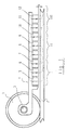
- FIG. 1 shows schematically a magnetic coil arrangement according to the invention.
- FIG. 1 shows a rail vehicle in the area of a bogie, of which only one wheel 1 is shown here, on a Rail 2 is running.
- a support arm 4th attached on an axis 3 of the wheel 1 .
- At the bottom of the support arm 4 are in one Distance h above the top of the rail 2 multiple solenoids 5-12 arranged in the direction of travel one behind the other.
- the magnetic coils can be subdivide into groups I, II, III.
- groups I, III lie the north poles below, i. they face the top of the rail.
- the South pole facing the rail top.
- magnetic field characteristics a here by dashed lines magnetic field lines are indicated.
Landscapes
- Engineering & Computer Science (AREA)
- Mechanical Engineering (AREA)
- Physics & Mathematics (AREA)
- Electromagnetism (AREA)
- Transportation (AREA)
- Electric Propulsion And Braking For Vehicles (AREA)
- Linear Motors (AREA)
Description
- Die lineare Wirbelstrommaschine wirkt bei uneingeschränkter Bremsfunktion in der Betriebsart "Traktion" unterstützend.
- Anfahrzeiten werden reduziert, da durch die zusätzlichen magnetischen Anzugskräfte, insbesondere bei schlechten Kraftschlußbedingungen, beispielsweise bei nassen Schienen, die Traktionsleistung unvermindert aufgeschaltet werden kann, ohne daß die Räder durchdrehen. Die Erfindung eignet sich somit insbesondere für Lokomotiven von Güterzügen. Durch Umschalten in den Schaltzustand "Bremsen" ist mit der Wirbelstrommaschine verschleißfreie und haftwertunabhängige Bremsung möglich, wodurch die anderen Bremssysteme geschont werden können.
- Die lineare Wirbelstrommaschine ist nicht nur für den Hochgeschwindigkeitsverkehr, sondern auch bis Geschwindigkeiten von 140 bis 160 km/h gut geeignet.
- An Streckensteigungen mit geringem Kraftschluß kann leichter und sicherer angefahren und die Fahrgeschwindigkeit schneller gesteigert werden.
- Es wird ein geringer Verschleiß erreicht, was die Lebenszykluskosten senkt.
- Züge mit einem leichten Steuer- oder Triebwagen können mit Hilfe der zusätzlichen magnetischen Anzugskraft auch bei starkem Seitenwind uneingeschränkt schnell fahren, wodurch sich die Entgleisungssicherheit erhöht und die Fahrtzeit verkürzt.
- Die lineare Wirbelstrommaschine gemäß der Erfindung ist universell bei einer Vielzahl von Fahrzeugtypen einsetzbar.
Claims (4)
- Magnetspulenanordnung für Schienenfahrzeuge mit Magnetspulen zur Erzeugung von Magnetfeldern, wobei die Magnetspulen in Fahrtrichtung hintereinander in einem Abstand von der Schienenoberseite am Schienenfahrzeug angeordnet sind, dadurch gekennzeichnet, daß die Magnetspulen (5-12) so geschaltet sind, daß die Magnetfelder mehrerer in Fahrtrichtung aufeinanderfolgender Magnetspulen (5-12) die gleiche Orientierung haben.
- Magnetspulenanordnung nach Anspruch 1, dadurch gekennzeichnet, daß mindestens zwei Gruppen (I, II, III) mit jeweils mindestens zwei gleichgeschalteten Magnetspulen (5-7; 8-10) vorgesehen sind.
- Magnetspulenanordnung nach einem der Ansprüche 1 oder 2, dadurch gekennzeichnet, daß die Magnetspulen (5-12) in einen Zustand umschaltbar sind, bei dem die Magnetfeldrichtung in Fahrtrichtung aufeinanderfolgender Magnetspulen (5-12) von Spule zu Spule wechselt.
- Magnetspulenanordnung nach einem der Ansprüche 1 bis 3, dadurch gekennzeichnet, daß die Magnetspulen (5-12) unmittelbar über den Schienen (2) angeordnet sind, wobei die Nord-Süd-Richtung der Magnetspulen (5-12) ortogonal zur Fahrtrichtung ist.
Applications Claiming Priority (3)
| Application Number | Priority Date | Filing Date | Title |
|---|---|---|---|
| DE10154775A DE10154775A1 (de) | 2001-11-08 | 2001-11-08 | Magnetspulenanordnung für Schienenfahrzeuge zur Verbesserung der Traktion |
| DE10154775 | 2001-11-08 | ||
| PCT/EP2002/012365 WO2003040539A2 (de) | 2001-11-08 | 2002-11-06 | Magnetspulenanordnung für schienenfahrzeuge zur verbesserung der traktion |
Publications (2)
| Publication Number | Publication Date |
|---|---|
| EP1448422A2 EP1448422A2 (de) | 2004-08-25 |
| EP1448422B1 true EP1448422B1 (de) | 2005-06-01 |
Family
ID=7704972
Family Applications (1)
| Application Number | Title | Priority Date | Filing Date |
|---|---|---|---|
| EP02802648A Expired - Lifetime EP1448422B1 (de) | 2001-11-08 | 2002-11-06 | Magnetspulenanordnung für schienenfahrzeuge zur verbesserung der traktion |
Country Status (6)
| Country | Link |
|---|---|
| EP (1) | EP1448422B1 (de) |
| AT (1) | ATE296740T1 (de) |
| AU (1) | AU2002363460A1 (de) |
| DE (2) | DE10154775A1 (de) |
| TW (1) | TW590919B (de) |
| WO (1) | WO2003040539A2 (de) |
Cited By (1)
| Publication number | Priority date | Publication date | Assignee | Title |
|---|---|---|---|---|
| DE102015107346A1 (de) * | 2015-05-11 | 2016-11-17 | Knorr-Bremse Systeme für Schienenfahrzeuge GmbH | Modulare Vorrichtung zum Koppeln eines Magnetsegmentes an zumindest eine Achse eines Schienenfahrzeuges |
Family Cites Families (3)
| Publication number | Priority date | Publication date | Assignee | Title |
|---|---|---|---|---|
| SE371147B (de) * | 1973-03-22 | 1974-11-11 | Asea Ab | |
| DE19503365C2 (de) * | 1995-02-02 | 2000-11-02 | Knorr Bremse Systeme | Lineare Wirbelstrombremse und Verfahren zur Steuerung einer linearen Wirbelstrombremse |
| DE19618903C2 (de) * | 1996-05-10 | 1998-03-19 | Knorr Bremse Systeme | Magnetische Bremse, insbesondere lineare Wirbelstrombremse |
-
2001
- 2001-11-08 DE DE10154775A patent/DE10154775A1/de not_active Withdrawn
-
2002
- 2002-10-22 TW TW091124402A patent/TW590919B/zh active
- 2002-11-06 WO PCT/EP2002/012365 patent/WO2003040539A2/de not_active Ceased
- 2002-11-06 AU AU2002363460A patent/AU2002363460A1/en not_active Abandoned
- 2002-11-06 DE DE50203301T patent/DE50203301D1/de not_active Expired - Lifetime
- 2002-11-06 AT AT02802648T patent/ATE296740T1/de not_active IP Right Cessation
- 2002-11-06 EP EP02802648A patent/EP1448422B1/de not_active Expired - Lifetime
Cited By (1)
| Publication number | Priority date | Publication date | Assignee | Title |
|---|---|---|---|---|
| DE102015107346A1 (de) * | 2015-05-11 | 2016-11-17 | Knorr-Bremse Systeme für Schienenfahrzeuge GmbH | Modulare Vorrichtung zum Koppeln eines Magnetsegmentes an zumindest eine Achse eines Schienenfahrzeuges |
Also Published As
| Publication number | Publication date |
|---|---|
| WO2003040539A3 (de) | 2003-12-24 |
| AU2002363460A1 (en) | 2003-05-19 |
| DE10154775A1 (de) | 2003-05-22 |
| WO2003040539A2 (de) | 2003-05-15 |
| TW590919B (en) | 2004-06-11 |
| DE50203301D1 (de) | 2005-07-07 |
| ATE296740T1 (de) | 2005-06-15 |
| EP1448422A2 (de) | 2004-08-25 |
Similar Documents
| Publication | Publication Date | Title |
|---|---|---|
| EP2109550B1 (de) | Magnetschwebebahn und verfahren zu deren betrieb | |
| EP1725418B1 (de) | Magnetschwebebahn mit einer wirbelstrombremse | |
| DE102007059504A1 (de) | Magnetschwebebahn | |
| DE19600187A1 (de) | Eisenbahnwagengleisbrems- und/oder -beschleunigungsmechanismus | |
| DE10160247A1 (de) | Kombifahrzeug zur Nutzung auf Schienenwege | |
| EP0840688B1 (de) | Magnetische bremse, insbesondere lineare wirbelstrombremse | |
| DE2710156C2 (de) | Magnetbahn | |
| DE2541599A1 (de) | Integrierte magnetfahrtechnik fuer den nahverkehr | |
| US3548751A (en) | Electric linear locomotive | |
| CA1091314A (en) | Attractive type electromagnetic device for magnetic levitation running vehicles | |
| Glatzel et al. | The development of the magnetically suspended transportation system in the federal republic of germany | |
| DE19718840C1 (de) | Antriebsmittel für eine Linearbewegung, insbesondere kontinuierliche Linearbewegung und Langstator-Linearmotor | |
| DE102022206679A1 (de) | Elektrisches Antriebssystem | |
| US3941062A (en) | Electromagnetic system for transversely aligning railway rolling stock on rails | |
| EP1448422A2 (de) | Magnetspulenanordnung für schienenfahrzeuge zur verbesserung der traktion | |
| DE2247858A1 (de) | Magnetische schwebebahn | |
| JP3342233B2 (ja) | リニアモーターカーの誘導車及びこれを用いる誘導方法 | |
| EP1236608A1 (de) | Eisenbahn-System | |
| DE1563970A1 (de) | Gleisfahrzeug mit elektrischem Antrieb durch zumindest einen linearen Induktionsmotor | |
| DE1563970C (de) | Gleisfahrzeug mit elektrischem Antrieb durch zumindest einen linearen Induktionsmotor | |
| DE19630302A1 (de) | Fahrortabhängige Geschwindigkeitssteuerung von Fahrzeugen mit Drehstromantrieb durch frequenzgesteuerte Umrichter | |
| DE102015005137A1 (de) | Magnetischer Kreis mit integrierten Funktionen für Transportaufgaben | |
| DE102006035092A1 (de) | Transportverband und Waggon mit Synchron-Linearmotor | |
| RU13782U1 (ru) | Система электродинамического подвеса | |
| JP2611837B2 (ja) | モノレ−ル車両走行装置 |
Legal Events
| Date | Code | Title | Description |
|---|---|---|---|
| PUAI | Public reference made under article 153(3) epc to a published international application that has entered the european phase |
Free format text: ORIGINAL CODE: 0009012 |
|
| 17P | Request for examination filed |
Effective date: 20040624 |
|
| AK | Designated contracting states |
Kind code of ref document: A2 Designated state(s): AT BE BG CH CY CZ DE DK EE ES FI FR GB GR IE IT LI LU MC NL PT SE SK TR |
|
| AX | Request for extension of the european patent |
Extension state: AL LT LV MK RO SI |
|
| GRAP | Despatch of communication of intention to grant a patent |
Free format text: ORIGINAL CODE: EPIDOSNIGR1 |
|
| RIN1 | Information on inventor provided before grant (corrected) |
Inventor name: KROEGER, UWE Inventor name: HOFMANN, MARTINA Inventor name: WERLE, THOMAS Inventor name: BINDER, ANDREAS Inventor name: GRAUTSTUECK, HEINRICH |
|
| GRAS | Grant fee paid |
Free format text: ORIGINAL CODE: EPIDOSNIGR3 |
|
| GRAA | (expected) grant |
Free format text: ORIGINAL CODE: 0009210 |
|
| AK | Designated contracting states |
Kind code of ref document: B1 Designated state(s): AT BE BG CH CY CZ DE DK EE ES FI FR GB GR IE IT LI LU MC NL PT SE SK TR |
|
| PG25 | Lapsed in a contracting state [announced via postgrant information from national office to epo] |
Ref country code: IT Free format text: LAPSE BECAUSE OF FAILURE TO SUBMIT A TRANSLATION OF THE DESCRIPTION OR TO PAY THE FEE WITHIN THE PRESCRIBED TIME-LIMIT;WARNING: LAPSES OF ITALIAN PATENTS WITH EFFECTIVE DATE BEFORE 2007 MAY HAVE OCCURRED AT ANY TIME BEFORE 2007. THE CORRECT EFFECTIVE DATE MAY BE DIFFERENT FROM THE ONE RECORDED. Effective date: 20050601 Ref country code: TR Free format text: LAPSE BECAUSE OF FAILURE TO SUBMIT A TRANSLATION OF THE DESCRIPTION OR TO PAY THE FEE WITHIN THE PRESCRIBED TIME-LIMIT Effective date: 20050601 Ref country code: FI Free format text: LAPSE BECAUSE OF FAILURE TO SUBMIT A TRANSLATION OF THE DESCRIPTION OR TO PAY THE FEE WITHIN THE PRESCRIBED TIME-LIMIT Effective date: 20050601 Ref country code: CZ Free format text: LAPSE BECAUSE OF FAILURE TO SUBMIT A TRANSLATION OF THE DESCRIPTION OR TO PAY THE FEE WITHIN THE PRESCRIBED TIME-LIMIT Effective date: 20050601 Ref country code: SK Free format text: LAPSE BECAUSE OF FAILURE TO SUBMIT A TRANSLATION OF THE DESCRIPTION OR TO PAY THE FEE WITHIN THE PRESCRIBED TIME-LIMIT Effective date: 20050601 Ref country code: GB Free format text: LAPSE BECAUSE OF FAILURE TO SUBMIT A TRANSLATION OF THE DESCRIPTION OR TO PAY THE FEE WITHIN THE PRESCRIBED TIME-LIMIT Effective date: 20050601 Ref country code: NL Free format text: LAPSE BECAUSE OF FAILURE TO SUBMIT A TRANSLATION OF THE DESCRIPTION OR TO PAY THE FEE WITHIN THE PRESCRIBED TIME-LIMIT Effective date: 20050601 Ref country code: IE Free format text: LAPSE BECAUSE OF FAILURE TO SUBMIT A TRANSLATION OF THE DESCRIPTION OR TO PAY THE FEE WITHIN THE PRESCRIBED TIME-LIMIT Effective date: 20050601 Ref country code: EE Free format text: LAPSE BECAUSE OF FAILURE TO SUBMIT A TRANSLATION OF THE DESCRIPTION OR TO PAY THE FEE WITHIN THE PRESCRIBED TIME-LIMIT Effective date: 20050601 |
|
| REG | Reference to a national code |
Ref country code: GB Ref legal event code: FG4D Free format text: NOT ENGLISH |
|
| REG | Reference to a national code |
Ref country code: CH Ref legal event code: EP |
|
| REF | Corresponds to: |
Ref document number: 50203301 Country of ref document: DE Date of ref document: 20050707 Kind code of ref document: P |
|
| REG | Reference to a national code |
Ref country code: IE Ref legal event code: FG4D Free format text: LANGUAGE OF EP DOCUMENT: GERMAN |
|
| PG25 | Lapsed in a contracting state [announced via postgrant information from national office to epo] |
Ref country code: BG Free format text: LAPSE BECAUSE OF FAILURE TO SUBMIT A TRANSLATION OF THE DESCRIPTION OR TO PAY THE FEE WITHIN THE PRESCRIBED TIME-LIMIT Effective date: 20050901 Ref country code: SE Free format text: LAPSE BECAUSE OF FAILURE TO SUBMIT A TRANSLATION OF THE DESCRIPTION OR TO PAY THE FEE WITHIN THE PRESCRIBED TIME-LIMIT Effective date: 20050901 Ref country code: DK Free format text: LAPSE BECAUSE OF FAILURE TO SUBMIT A TRANSLATION OF THE DESCRIPTION OR TO PAY THE FEE WITHIN THE PRESCRIBED TIME-LIMIT Effective date: 20050901 Ref country code: GR Free format text: LAPSE BECAUSE OF FAILURE TO SUBMIT A TRANSLATION OF THE DESCRIPTION OR TO PAY THE FEE WITHIN THE PRESCRIBED TIME-LIMIT Effective date: 20050901 |
|
| PG25 | Lapsed in a contracting state [announced via postgrant information from national office to epo] |
Ref country code: ES Free format text: LAPSE BECAUSE OF FAILURE TO SUBMIT A TRANSLATION OF THE DESCRIPTION OR TO PAY THE FEE WITHIN THE PRESCRIBED TIME-LIMIT Effective date: 20050912 |
|
| PG25 | Lapsed in a contracting state [announced via postgrant information from national office to epo] |
Ref country code: PT Free format text: LAPSE BECAUSE OF FAILURE TO SUBMIT A TRANSLATION OF THE DESCRIPTION OR TO PAY THE FEE WITHIN THE PRESCRIBED TIME-LIMIT Effective date: 20051103 |
|
| PG25 | Lapsed in a contracting state [announced via postgrant information from national office to epo] |
Ref country code: CY Free format text: LAPSE BECAUSE OF FAILURE TO SUBMIT A TRANSLATION OF THE DESCRIPTION OR TO PAY THE FEE WITHIN THE PRESCRIBED TIME-LIMIT Effective date: 20051106 Ref country code: AT Free format text: LAPSE BECAUSE OF NON-PAYMENT OF DUE FEES Effective date: 20051106 |
|
| PG25 | Lapsed in a contracting state [announced via postgrant information from national office to epo] |
Ref country code: MC Free format text: LAPSE BECAUSE OF NON-PAYMENT OF DUE FEES Effective date: 20051130 Ref country code: LU Free format text: LAPSE BECAUSE OF NON-PAYMENT OF DUE FEES Effective date: 20051130 Ref country code: BE Free format text: LAPSE BECAUSE OF NON-PAYMENT OF DUE FEES Effective date: 20051130 |
|
| NLV1 | Nl: lapsed or annulled due to failure to fulfill the requirements of art. 29p and 29m of the patents act | ||
| GBV | Gb: ep patent (uk) treated as always having been void in accordance with gb section 77(7)/1977 [no translation filed] |
Effective date: 20050601 |
|
| REG | Reference to a national code |
Ref country code: IE Ref legal event code: FD4D |
|
| PLBE | No opposition filed within time limit |
Free format text: ORIGINAL CODE: 0009261 |
|
| STAA | Information on the status of an ep patent application or granted ep patent |
Free format text: STATUS: NO OPPOSITION FILED WITHIN TIME LIMIT |
|
| ET | Fr: translation filed | ||
| 26N | No opposition filed |
Effective date: 20060302 |
|
| PG25 | Lapsed in a contracting state [announced via postgrant information from national office to epo] |
Ref country code: LI Free format text: LAPSE BECAUSE OF NON-PAYMENT OF DUE FEES Effective date: 20061130 Ref country code: CH Free format text: LAPSE BECAUSE OF NON-PAYMENT OF DUE FEES Effective date: 20061130 |
|
| REG | Reference to a national code |
Ref country code: CH Ref legal event code: PL |
|
| BERE | Be: lapsed |
Owner name: KNORR-BREMSE SYSTEME FUR SCHIENENFAHRZEUGE G.M.B.H Effective date: 20051130 |
|
| REG | Reference to a national code |
Ref country code: FR Ref legal event code: PLFP Year of fee payment: 14 |
|
| PGFP | Annual fee paid to national office [announced via postgrant information from national office to epo] |
Ref country code: DE Payment date: 20151119 Year of fee payment: 14 |
|
| PGFP | Annual fee paid to national office [announced via postgrant information from national office to epo] |
Ref country code: FR Payment date: 20151124 Year of fee payment: 14 |
|
| REG | Reference to a national code |
Ref country code: DE Ref legal event code: R119 Ref document number: 50203301 Country of ref document: DE |
|
| REG | Reference to a national code |
Ref country code: FR Ref legal event code: ST Effective date: 20170731 |
|
| PG25 | Lapsed in a contracting state [announced via postgrant information from national office to epo] |
Ref country code: FR Free format text: LAPSE BECAUSE OF NON-PAYMENT OF DUE FEES Effective date: 20161130 |
|
| PG25 | Lapsed in a contracting state [announced via postgrant information from national office to epo] |
Ref country code: DE Free format text: LAPSE BECAUSE OF NON-PAYMENT OF DUE FEES Effective date: 20170601 |