EP1448334B1 - Verfahren und Vorrichtung zur Erfassung der Nahtqualität einer Schweißnaht bei der Schweißung von Werkstücken - Google Patents
Verfahren und Vorrichtung zur Erfassung der Nahtqualität einer Schweißnaht bei der Schweißung von Werkstücken Download PDFInfo
- Publication number
- EP1448334B1 EP1448334B1 EP02774233A EP02774233A EP1448334B1 EP 1448334 B1 EP1448334 B1 EP 1448334B1 EP 02774233 A EP02774233 A EP 02774233A EP 02774233 A EP02774233 A EP 02774233A EP 1448334 B1 EP1448334 B1 EP 1448334B1
- Authority
- EP
- European Patent Office
- Prior art keywords
- image
- seam
- sensor
- light
- welding
- Prior art date
- Legal status (The legal status is an assumption and is not a legal conclusion. Google has not performed a legal analysis and makes no representation as to the accuracy of the status listed.)
- Expired - Lifetime
Links
Images
Classifications
-
- B—PERFORMING OPERATIONS; TRANSPORTING
- B23—MACHINE TOOLS; METAL-WORKING NOT OTHERWISE PROVIDED FOR
- B23K—SOLDERING OR UNSOLDERING; WELDING; CLADDING OR PLATING BY SOLDERING OR WELDING; CUTTING BY APPLYING HEAT LOCALLY, e.g. FLAME CUTTING; WORKING BY LASER BEAM
- B23K9/00—Arc welding or cutting
- B23K9/12—Automatic feeding or moving of electrodes or work for spot or seam welding or cutting
- B23K9/127—Means for tracking lines during arc welding or cutting
-
- B—PERFORMING OPERATIONS; TRANSPORTING
- B23—MACHINE TOOLS; METAL-WORKING NOT OTHERWISE PROVIDED FOR
- B23K—SOLDERING OR UNSOLDERING; WELDING; CLADDING OR PLATING BY SOLDERING OR WELDING; CUTTING BY APPLYING HEAT LOCALLY, e.g. FLAME CUTTING; WORKING BY LASER BEAM
- B23K26/00—Working by laser beam, e.g. welding, cutting or boring
- B23K26/02—Positioning or observing the workpiece, e.g. with respect to the point of impact; Aligning, aiming or focusing the laser beam
- B23K26/03—Observing, e.g. monitoring, the workpiece
- B23K26/032—Observing, e.g. monitoring, the workpiece using optical means
-
- B—PERFORMING OPERATIONS; TRANSPORTING
- B23—MACHINE TOOLS; METAL-WORKING NOT OTHERWISE PROVIDED FOR
- B23K—SOLDERING OR UNSOLDERING; WELDING; CLADDING OR PLATING BY SOLDERING OR WELDING; CUTTING BY APPLYING HEAT LOCALLY, e.g. FLAME CUTTING; WORKING BY LASER BEAM
- B23K26/00—Working by laser beam, e.g. welding, cutting or boring
- B23K26/02—Positioning or observing the workpiece, e.g. with respect to the point of impact; Aligning, aiming or focusing the laser beam
- B23K26/04—Automatically aligning, aiming or focusing the laser beam, e.g. using the back-scattered light
- B23K26/044—Seam tracking
-
- B—PERFORMING OPERATIONS; TRANSPORTING
- B23—MACHINE TOOLS; METAL-WORKING NOT OTHERWISE PROVIDED FOR
- B23K—SOLDERING OR UNSOLDERING; WELDING; CLADDING OR PLATING BY SOLDERING OR WELDING; CUTTING BY APPLYING HEAT LOCALLY, e.g. FLAME CUTTING; WORKING BY LASER BEAM
- B23K9/00—Arc welding or cutting
- B23K9/095—Monitoring or automatic control of welding parameters
- B23K9/0956—Monitoring or automatic control of welding parameters using sensing means, e.g. optical
-
- B—PERFORMING OPERATIONS; TRANSPORTING
- B23—MACHINE TOOLS; METAL-WORKING NOT OTHERWISE PROVIDED FOR
- B23K—SOLDERING OR UNSOLDERING; WELDING; CLADDING OR PLATING BY SOLDERING OR WELDING; CUTTING BY APPLYING HEAT LOCALLY, e.g. FLAME CUTTING; WORKING BY LASER BEAM
- B23K9/00—Arc welding or cutting
- B23K9/12—Automatic feeding or moving of electrodes or work for spot or seam welding or cutting
- B23K9/127—Means for tracking lines during arc welding or cutting
- B23K9/1272—Geometry oriented, e.g. beam optical trading
- B23K9/1274—Using non-contact, optical means, e.g. laser means
-
- G—PHYSICS
- G01—MEASURING; TESTING
- G01B—MEASURING LENGTH, THICKNESS OR SIMILAR LINEAR DIMENSIONS; MEASURING ANGLES; MEASURING AREAS; MEASURING IRREGULARITIES OF SURFACES OR CONTOURS
- G01B11/00—Measuring arrangements characterised by the use of optical techniques
- G01B11/30—Measuring arrangements characterised by the use of optical techniques for measuring roughness or irregularity of surfaces
- G01B11/303—Measuring arrangements characterised by the use of optical techniques for measuring roughness or irregularity of surfaces using photoelectric detection means
-
- B—PERFORMING OPERATIONS; TRANSPORTING
- B23—MACHINE TOOLS; METAL-WORKING NOT OTHERWISE PROVIDED FOR
- B23K—SOLDERING OR UNSOLDERING; WELDING; CLADDING OR PLATING BY SOLDERING OR WELDING; CUTTING BY APPLYING HEAT LOCALLY, e.g. FLAME CUTTING; WORKING BY LASER BEAM
- B23K2101/00—Articles made by soldering, welding or cutting
- B23K2101/18—Sheet panels
- B23K2101/185—Tailored blanks
Definitions
- the invention relates to a method according to the preamble of claim 1 and to a device according to the preamble of claim 10.
- a light beam for example a laser beam
- a laser line is placed over a weld seam and detected by means of a CMOS camera.
- a refresh rate of 500 Hz is used.
- An optical control of the measurement window for the laser lines is done with a gray value image in reflected light illumination, which is generated only in strips and therefore has a refresh rate of only 16 Hz and, as I said, only serves to control the light-section process.
- a light section projector and a CCD camera is used, wherein also a video image is recorded with incident illumination.
- the video image is evaluated for brightness signal and its derivative to determine the position of the butt joint, which can also be done with the light section method.
- DE-A-43 12 241 a position detection with light-section method and gray image evaluation of an image recorded by means of a two-dimensional CCD array is likewise described, wherein light-section and gray-image evaluation take place intermittently. Also in the detection of the joint after the joining step, ie, for example, the weld, it is known to apply the light-section method.
- the DE 43 12 241 A1 describes a method and a device for detecting the position of a seam, in which a light-section method and a gray-image evaluation are combined in such a way that both are used in an alternating manner, whereby different partial information is obtained.
- a two-dimensional CCD array is used as the areal image recorder.
- the light section evaluation serves to detect the position of the workpiece surface relative to a reference coordinate system, while the gray image evaluation serves to detect the position of the seam for seam tracking.
- the DE 44 08 226 A1 describes a measuring device for the process-coupled determination of the roughness of technical surfaces by evaluating di- or polychromatic speckle patterns.
- a rough surface having a partially coherent light source is illuminated through a beam splitter, the reflected light being projected onto a detector array by means of a convex lens.
- the image data are stored pixel-synchronously by means of an image data acquisition unit as gray values and provided to a digital computer for further processing.
- the speckle pattern can be observed on a monitor, thereby adjusting the measurement setup.
- surface parameters of the rough surface such as a root mean square roughness or a preferred direction of roughness, as in the case of ground surfaces, can be determined.
- a detector comprises a laser oscillator, a vibratable mirror, by which a scanning movement of the laser beam is generated on a workpiece, an optical system for receiving the light reflected from the workpiece and a light receiving element, on which the reflected light through the optical System is projected.
- the light receiving element is connected to a signal detector, which in turn is connected to an input / output device.
- the input / output device is further connected to a laser driver and a mirror scanner.
- the data of the signal detector are transmitted via a control line to a robot controller, which evaluates the received signal of the signal detector to control a welding robot.
- the US 4,591,689 A describes an adaptive welding guide device.
- a laser beam is projected on a workpiece by means of a projector and recorded by a camera.
- the projector is designed to project a line of light onto the workpiece which reciprocates perpendicularly to a position to be joined at a predetermined speed, the position of the center, the position of the left edge, the position of the right edge, determine the height of the left edge, the height of the right edge, the depth and the area of the site to be joined.
- the DE 102 22 786 A1 describes a method for positioning workpieces in laser processing processes.
- an image of a workpiece is detected directly with a camera and the position of the workpiece is determined from this image by means of a downstream image processing system.
- This actual position is compared with a predetermined desired position and the position of the workpiece is optionally readjusted via a machine control, for which purpose the machine control controls the linear and rotational axes of the workpiece feed.
- the workpiece is additionally illuminated by an external illumination unit, wherein a geometric figure is projected onto the surface of the workpiece.
- the rays reflected from the workpiece into the focusing lens are imaged via another lens onto the image sensor of the logarithmic CMOS camera.
- the deformed image of the projected figure allows the three-dimensional shape of the workpiece to be calculated.
- the invention is first based on the object to provide an improved method for detecting the seam quality of a weld.
- the gray value image can be evaluated for detecting edge damage and for measuring the gap width.
- the method is used after the joining step, especially in the evaluation of welds.
- the sensor used is a CMOS sensor arrangement, preferably a single CMOS sensor, which has a substantially linear characteristic at low illuminance and a characteristic deviating therefrom at higher illuminances, preferably a curved, at best logarithmic characteristic what the recording of the gray value image with its illumination, which is preferably a dark field illumination, and the light pattern of the light section method by the sensor or, the separation of these mild parts significantly improved in the evaluation.
- a color image can be recorded, which allows additional separation due to the different wavelengths of the two light sources.
- the evaluation is preferably carried out for the weld quality by determining texture features of the weld from the image, e.g. by analysis of contour lines. A lack of certain features is e.g. rated as poor quality.
- the invention is further based on the object to provide a device for the evaluation of welds.
- the invention has for its object to improve the position detection of the joint, in particular before the joining step, ie when welding the edge detection for guiding the welding beam and simplify.
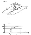
- FIG. 1 schematically shows the welding of a board or a tailored blanks, which is formed from the sheets 1 and 2, which butt along a joint line 3 blunt. It is usually flat sheet metal parts of different thickness and / or different sheet properties to an element, the board (Tailored Blank) connected. This element is usually formed late into a component, eg to a component for an automobile.
- a laser beam 6 from a laser beam source 5 is guided along the joint line 3 and welded together the sheets 1 and 2 and forms behind the weld 4. It is irrelevant whether the laser beam source 5 over stationary workpieces or whether the workpieces moved past a fixed laser become.
- the unit 7 comprises means for generating at least one light line, in particular a laser light line, substantially transverse to the course of the joint line 3.
- the course of the light line is detected by a camera to approach the joint line detect. This is basically known and need not be further explained here.
- the detected area is indicated in the figure with 8, which is not true to scale; the detected area can be eg 8x8 mm or 10x10 mm.
- the image of the unit 7 is delivered via a line 12 to the evaluation unit and control unit 11, which may also be separate units for evaluation and control, and accordingly, the position of the laser beam for accurate tracking of the joint 3 is controlled.
- a seam inspection unit 9 is provided.
- the area covered by this is, again not to scale and including, for example, also 8x8 mm or 10x10 mm, indicated as area 10 in the figure.
- the procedure is now such that, in particular for testing the weld seam 4, both the light-slit method is used and a gray scale image is recorded, wherein the gray-scale image is evaluated to detect the quality of the weld seam.
- This evaluation of the gray-scale image should in particular determine local imperfections such as porosity, small holes and missing welds.
- the unit 9 is designed to generate at least one light line transverse to the weld 4.
- the light line is preferably generated by a light-section laser with high optical power (eg from 50 mW to 100 mW laser diodes on a narrow line) to always bring enough light to the sensor in the unit 9 in the present different reflection properties of the surfaces, the picks up the light line.
- the sensor in the unit 9 for the light line is preferably a CMOS sensor or a CMOS camera.
- the exposure time of the camera sensor is preferably chosen so long that the reflected light of the laser line is averaged over a portion of the surface. The 3D measurement thus comes about over an area that is larger than the line width of the laser. .
- the flash exposure is as short as possible, the illumination time of the illumination being short in order to compensate for the motion blur
- welding seam moving relative to the unit 9 is smaller than one pixel.
- the lighting is preferably done with dark field lighting, possibly instead in the Bright field.
- the sensor for recording the gray level image is also a CMOS sensor and preferably the same sensor that also receives the laser line.
- an image is taken by means of only one sensor, in particular a CMOS sensor or a CMOS camera, each in short successive time periods, which includes both a gray value image of the weld seam and the image of the laser line.
- the distance of the image recordings is chosen so that an overlap of the object area, ie a complete recording of the seam, is guaranteed.
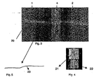
- FIG. 3 a corresponding image recording is shown, which shows the workpieces 1 and 2 and the weld 4, and the laser line 20th
- FIG. 1 schematically shows the receiving area 10, which is shown in enlarged scale in the figure, and is typically 10x10 mm or 8x8 mm, for example, in the laser welding of boards. For example, 60 frames per second are recorded for quality control during blank welding.
- the relative movement between the unit 9 or the CMOS camera and the weld seam 4 can be, for example, 500 mm / second.
- FIG. 2 shows a preferred characteristic, wherein on the X-axis, the intensity of the incident light on the sensor is shown and on the Y-axis, the corresponding response of the sensor and the sensor output signal as a bit value.
- the sensor output signal consists of a 10-bit word each. It can be seen that with a lower illuminance in the region A or within the distance ab on the X-axis, a linear characteristic 16 is provided.
- the sensor characteristic is not linear, preferably logarithmic. This allows the detection of the laser line even with large fluctuations in brightness or fluctuations in the reflection properties of the workpiece surfaces and the weld.
- the image of the laser line is output from the sensor in the range of 801-1024 of the 10-bit word.
- Two sensors can be provided which have the corresponding characteristic curves 16 or 17 and are arranged in the unit 9 in such a way that they essentially observe the same detection area 10.
- a single sensor which has an overall characteristic 18, which is composed of the characteristic sections 16 and 17.
- Such a sensor is available from Photonfocus AG, 8853 Lachen, Switzerland, on the market under the type designation MV-D1024 CL80.
- the characteristic curve of the sensor is thus adapted so that the scattered light of the flash illumination for the gray scale image detection lies in the lower linear range of the sensor response, which is preferably a dark field illumination; in the upper area lies the reflected light of the line laser.
- the properties of the sensor can be exploited in such a way that both types of lighting can be combined in one picture. By using only one sensor, the expenditure on equipment and the effort for the operator is lowered and also the maintenance effort.
- a color sensor can also be used. This may cause the separation of the representation In the image of the light line of the triangulation laser and the dark field illumination of the seam on the separation of the wavelengths of light can be further improved.
- the dark field illumination is preferably below 680 nm, the line laser above this wavelength.
- the images taken by the sensor are applied to an image evaluation unit 11.
- an image evaluation unit 11 There is, for example, a picture according to FIG. 3 before, wherein the image for the evaluation unit 11 must not be present in a visible representation, but only as a sequence of numbers. In this case, it is possible to operate in the unit 11 with 8-bit words.
- the separation of the grayscale values of the image can still take place in the 10-bit image, and the data can subsequently be transferred via corresponding tables (look-up tables) into the 8-bit areas 0-200 (for the grayscale image) and 200-255 (for the laser line).
- each image is carried out for the laser line in a conventional manner, wherein by means of the laser line, the cross profile of the seam can be determined, which is shown for explanation in Figure 5.
- the geometrical data of the seam e.g. Convexity, concavity and edge offset can be determined. These values are subject to ISO limits, compliance with which is recorded.
- the high-quality gray value image which is supplied by the unit 9, now also allows the assessment of the quality of the weld due to the evaluation of this image. For this purpose, in the image area, which represents the seam 4, the contours of the seam structure are highlighted.
- FIG. 4 this is shown for a seam portion, at 22 a processing step is shown where after dynamic binarization the seam structure is highlighted. In a further processing step according to region 21, the dynamically binarized Seam area skeletonized. Remain the contour lines of the seam structure.
- the corresponding image processing allows the detection of local defects, e.g. Porosity and small holes and missing fürschweissungen. On the one hand, this can be done by comparing the structures thus determined corresponding to regions 21 or 22 with known patterns of qualitatively good weld seams. It is also additionally or instead by the unit 11, the presence of the contour lines, their orientation or angular deviation from the seam longitudinal direction and / or their length are checked. In this way it is now possible to check the seam quality on the basis of a gray value image.
- the invention has been explained above with reference to a welding seam in board welding, but is not limited to this application.
- the quality of joints can be tested in this way, e.g. a spot weld or a bead of an adhesive.
- the invention can be used. All embodiments explained with reference to the unit 9 are hereby also indicated or adopted for the unit 7.
- the illumination and the image recording preferably also take place as explained with reference to the unit 9.
- the light line evaluation allows edge detection and the fat jump monitoring.
- the detection of the edge at zero gap / zero thickness jump and the measurement of the gap width is preferably done via the gray image evaluation.
- the preferred sensor configuration with a linear and logarithmic characteristic and the preferred illumination mode provides a qualitatively very good grayscale image with high resolution, large object field, large dynamic range despite high object speed, as was not the case in the prior art.
- the unit 7 is also connected via a line 12 to the image evaluation 11, as is the case with the line 14 for the unit 9.
- the laser source 5 is controlled or tracked by the unit 11 via the line 13 so that the welding by means of the laser beam takes place exactly at the location of the joint line 3.
- the unit 7 can perform the detection of edge damage in addition to the position detection, so perform the assessment of the quality of the joint before the joining step, as has been explained with reference to the unit 9. If the joint is an adhesive bead, the position and quality detection is likewise carried out by a unit corresponding to the unit 7 (or separated by two units) before the joining step.
Landscapes
- Physics & Mathematics (AREA)
- Engineering & Computer Science (AREA)
- Optics & Photonics (AREA)
- Plasma & Fusion (AREA)
- Mechanical Engineering (AREA)
- Geometry (AREA)
- General Physics & Mathematics (AREA)
- Length Measuring Devices By Optical Means (AREA)
- Laser Beam Processing (AREA)
- Investigating Materials By The Use Of Optical Means Adapted For Particular Applications (AREA)
- Investigating Or Analyzing Materials By The Use Of Ultrasonic Waves (AREA)
Applications Claiming Priority (3)
| Application Number | Priority Date | Filing Date | Title |
|---|---|---|---|
| CH210101 | 2001-11-15 | ||
| CH21012001 | 2001-11-15 | ||
| PCT/CH2002/000613 WO2003041902A1 (de) | 2001-11-15 | 2002-11-14 | Verfahren und vorrichtung zur bewertung von fügestellen von werkstücken |
Publications (2)
| Publication Number | Publication Date |
|---|---|
| EP1448334A1 EP1448334A1 (de) | 2004-08-25 |
| EP1448334B1 true EP1448334B1 (de) | 2011-04-20 |
Family
ID=4567514
Family Applications (1)
| Application Number | Title | Priority Date | Filing Date |
|---|---|---|---|
| EP02774233A Expired - Lifetime EP1448334B1 (de) | 2001-11-15 | 2002-11-14 | Verfahren und Vorrichtung zur Erfassung der Nahtqualität einer Schweißnaht bei der Schweißung von Werkstücken |
Country Status (10)
| Country | Link |
|---|---|
| US (1) | US7577285B2 (pt) |
| EP (1) | EP1448334B1 (pt) |
| JP (1) | JP4531396B2 (pt) |
| KR (1) | KR100922478B1 (pt) |
| AT (1) | ATE506138T1 (pt) |
| CA (1) | CA2465231C (pt) |
| DE (1) | DE50215016D1 (pt) |
| ES (1) | ES2363078T3 (pt) |
| PT (1) | PT1448334E (pt) |
| WO (1) | WO2003041902A1 (pt) |
Cited By (1)
| Publication number | Priority date | Publication date | Assignee | Title |
|---|---|---|---|---|
| EP4010145B1 (de) * | 2020-09-02 | 2023-10-18 | Precitec GmbH & Co. KG | Verfahren zum analysieren einer werkstückoberfläche für einen laserbearbeitungsprozess und eine analysevorrichtung zum analysieren einer werkstückoberfläche |
Families Citing this family (91)
| Publication number | Priority date | Publication date | Assignee | Title |
|---|---|---|---|---|
| US6627863B2 (en) * | 2000-12-15 | 2003-09-30 | Mitutoyo Corporation | System and methods to determine the settings of multiple light sources in a vision system |
| DE10361018C9 (de) * | 2003-12-23 | 2021-03-04 | QUISS Qualitäts-Inspektionssysteme und Service GmbH | Verfahren zum Erkennen einer auf einem Substrat aufzubringenden Struktur mit mehreren Kameras sowie eine Vorrichtung hierfür |
| EA009923B1 (ru) * | 2004-03-27 | 2008-04-28 | Тексмаг Гмбх | Устройство детектирования соединения листов резины |
| CA2463409A1 (en) * | 2004-04-02 | 2005-10-02 | Servo-Robot Inc. | Intelligent laser joining head |
| WO2006128317A1 (de) * | 2005-06-03 | 2006-12-07 | Elpatronic Ag | Verfahren zur beleuchtung und beleuchtungsanordnung |
| CN101479566B (zh) | 2005-11-14 | 2012-05-30 | 普雷茨特影像有限及两合公司 | 评价工件结合位置的方法和设备 |
| KR100797239B1 (ko) * | 2005-12-23 | 2008-01-23 | 주식회사 포스코 | 강판의 용접부 온라인 검출장치 및 방법 |
| KR101346648B1 (ko) * | 2006-09-06 | 2014-01-10 | 프리시텍 비전 게엠베하 운트 코. 카게 | 용접 공정 동안 용접 품질의 광학적 평가 방법 및 장치 |
| JP5154134B2 (ja) * | 2006-10-05 | 2013-02-27 | 株式会社キーエンス | 光学式変位計、光学式変位測定方法、光学式変位測定プログラム |
| JP2008175577A (ja) * | 2007-01-16 | 2008-07-31 | Jfe Steel Kk | 電縫溶接管溶接部監視方法及び監視装置並びに電縫溶接管の製造方法 |
| DE102007024789B3 (de) * | 2007-05-26 | 2008-10-23 | Trumpf Werkzeugmaschinen Gmbh + Co. Kg | Verfahren zum Erkennen von Fehlern an einer Schweißnaht während eines Laser-Schweißprozesses |
| US7692800B2 (en) * | 2007-08-03 | 2010-04-06 | Siemens Medical Solutions Usa, Inc. | Multi-level light curtain with structure light sources and imaging sensors |
| FR2923295B1 (fr) * | 2007-11-06 | 2009-12-11 | Areva Np | Procede et dispositif de visualisation et de controle du profil d'un cordon de soudure a l'interieur d'un chanfrein menage entre deux pieces metalliques |
| WO2009146359A1 (en) | 2008-05-28 | 2009-12-03 | Illinois Tool Works Inc. | Welding training system |
| DE102008032509A1 (de) * | 2008-07-10 | 2010-01-14 | Epcos Ag | Heizungsvorrichtung und Verfahren zur Herstellung der Heizungsvorrichtung |
| RU2529135C2 (ru) * | 2008-11-21 | 2014-09-27 | Прецитек Кг | Способ и устройство для контроля проводимого на обрабатываемой детали процесса лазерной обработки, а также лазерная обрабатывающая головка с подобным устройством |
| DE102009057209B4 (de) * | 2009-02-09 | 2012-06-28 | Scansonic Mi Gmbh | Vorrichtung mit Scanner-Optik zur Materialbearbeitung mittels Laser |
| DE102009042986B3 (de) * | 2009-09-25 | 2011-03-03 | Precitec Kg | Schweißkopf und Verfahren zum Fügen eines Werkstücks |
| DE102010030435A1 (de) * | 2010-06-23 | 2011-12-29 | Carl Zeiss Smt Gmbh | Metrologiesystem |
| JP5672480B2 (ja) * | 2010-08-30 | 2015-02-18 | スズキ株式会社 | ビードの終端部の形状を判定する装置及びその方法 |
| US8716627B2 (en) | 2010-09-10 | 2014-05-06 | Honeywell International Inc. | Welding systems and methods |
| DE102011104550B4 (de) * | 2011-06-17 | 2014-04-30 | Precitec Kg | Optische Messvorrichtung zur Überwachung einer Fügenaht, Fügekopf und Laserschweißkopf mit der selben |
| US9101994B2 (en) | 2011-08-10 | 2015-08-11 | Illinois Tool Works Inc. | System and device for welding training |
| US20130119040A1 (en) * | 2011-11-11 | 2013-05-16 | Lincoln Global, Inc. | System and method for adaptive fill welding using image capture |
| DE102012210012A1 (de) * | 2012-06-14 | 2013-12-19 | Bayerische Motoren Werke Aktiengesellschaft | Verfahren und Vorrichtung zum Laser-Remote-Schweißen von zwei beschichteten Blechen |
| WO2014026297A1 (de) * | 2012-08-15 | 2014-02-20 | Soutec Ag | Verfahren zur überwachung der kantenposition von zwei platinen und eine anwendung des verfahrens |
| US9583014B2 (en) | 2012-11-09 | 2017-02-28 | Illinois Tool Works Inc. | System and device for welding training |
| ES2702882T3 (es) | 2013-02-05 | 2019-03-06 | Comau Llc | Aparato y procedimiento de alimentación continua de elemento de fijación |
| CN103134809B (zh) * | 2013-03-14 | 2015-04-29 | 苏州华源包装股份有限公司 | 焊缝缺陷检测方法 |
| US9728103B2 (en) | 2013-03-15 | 2017-08-08 | Illinois Tool Works Inc. | Data storage and analysis for a welding training system |
| US9666100B2 (en) | 2013-03-15 | 2017-05-30 | Illinois Tool Works Inc. | Calibration devices for a welding training system |
| US9672757B2 (en) | 2013-03-15 | 2017-06-06 | Illinois Tool Works Inc. | Multi-mode software and method for a welding training system |
| US9583023B2 (en) | 2013-03-15 | 2017-02-28 | Illinois Tool Works Inc. | Welding torch for a welding training system |
| US9713852B2 (en) | 2013-03-15 | 2017-07-25 | Illinois Tool Works Inc. | Welding training systems and devices |
| EP2805800B1 (de) * | 2013-05-22 | 2015-09-16 | FFT EDAG Produktionssysteme GmbH & Co. KG | Fügen eines Werkstücks mit versteckter Fügenaht |
| US10040141B2 (en) * | 2013-05-23 | 2018-08-07 | Crc-Evans Pipeline International, Inc. | Laser controlled internal welding machine for a pipeline |
| US11767934B2 (en) | 2013-05-23 | 2023-09-26 | Crc-Evans Pipeline International, Inc. | Internally welded pipes |
| US10589371B2 (en) | 2013-05-23 | 2020-03-17 | Crc-Evans Pipeline International, Inc. | Rotating welding system and methods |
| US10480862B2 (en) | 2013-05-23 | 2019-11-19 | Crc-Evans Pipeline International, Inc. | Systems and methods for use in welding pipe segments of a pipeline |
| US10695876B2 (en) | 2013-05-23 | 2020-06-30 | Crc-Evans Pipeline International, Inc. | Self-powered welding systems and methods |
| US9821415B2 (en) | 2014-03-28 | 2017-11-21 | Crc-Evans Pipeline International, Inc. | Internal pipeline cooler |
| KR101481618B1 (ko) * | 2013-09-03 | 2015-01-12 | 주식회사 포스코 | 스트립의 용접 품질 판정 장치 및 판정 방법 |
| US10056010B2 (en) | 2013-12-03 | 2018-08-21 | Illinois Tool Works Inc. | Systems and methods for a weld training system |
| US9757819B2 (en) | 2014-01-07 | 2017-09-12 | Illinois Tool Works Inc. | Calibration tool and method for a welding system |
| US9751149B2 (en) | 2014-01-07 | 2017-09-05 | Illinois Tool Works Inc. | Welding stand for a welding system |
| US10105782B2 (en) | 2014-01-07 | 2018-10-23 | Illinois Tool Works Inc. | Feedback from a welding torch of a welding system |
| US10170019B2 (en) | 2014-01-07 | 2019-01-01 | Illinois Tool Works Inc. | Feedback from a welding torch of a welding system |
| US9589481B2 (en) | 2014-01-07 | 2017-03-07 | Illinois Tool Works Inc. | Welding software for detection and control of devices and for analysis of data |
| US9724788B2 (en) | 2014-01-07 | 2017-08-08 | Illinois Tool Works Inc. | Electrical assemblies for a welding system |
| CN106660154A (zh) * | 2014-03-25 | 2017-05-10 | 柯马有限责任公司 | 材料接合检查与修复 |
| US10307853B2 (en) | 2014-06-27 | 2019-06-04 | Illinois Tool Works Inc. | System and method for managing welding data |
| US10665128B2 (en) | 2014-06-27 | 2020-05-26 | Illinois Tool Works Inc. | System and method of monitoring welding information |
| US9862049B2 (en) | 2014-06-27 | 2018-01-09 | Illinois Tool Works Inc. | System and method of welding system operator identification |
| US9937578B2 (en) | 2014-06-27 | 2018-04-10 | Illinois Tool Works Inc. | System and method for remote welding training |
| US11014183B2 (en) | 2014-08-07 | 2021-05-25 | Illinois Tool Works Inc. | System and method of marking a welding workpiece |
| US9724787B2 (en) | 2014-08-07 | 2017-08-08 | Illinois Tool Works Inc. | System and method of monitoring a welding environment |
| US9875665B2 (en) | 2014-08-18 | 2018-01-23 | Illinois Tool Works Inc. | Weld training system and method |
| MX371071B (es) | 2014-08-29 | 2020-01-15 | Crc Evans Pipeline Int Inc Star | Método y sistema de soldadura. |
| US9545693B2 (en) * | 2014-10-07 | 2017-01-17 | Caterpillar Inc. | Consumable insert for welding |
| US10239147B2 (en) | 2014-10-16 | 2019-03-26 | Illinois Tool Works Inc. | Sensor-based power controls for a welding system |
| US11247289B2 (en) | 2014-10-16 | 2022-02-15 | Illinois Tool Works Inc. | Remote power supply parameter adjustment |
| US10490098B2 (en) | 2014-11-05 | 2019-11-26 | Illinois Tool Works Inc. | System and method of recording multi-run data |
| US10402959B2 (en) | 2014-11-05 | 2019-09-03 | Illinois Tool Works Inc. | System and method of active torch marker control |
| US10373304B2 (en) | 2014-11-05 | 2019-08-06 | Illinois Tool Works Inc. | System and method of arranging welding device markers |
| US10417934B2 (en) | 2014-11-05 | 2019-09-17 | Illinois Tool Works Inc. | System and method of reviewing weld data |
| US10210773B2 (en) | 2014-11-05 | 2019-02-19 | Illinois Tool Works Inc. | System and method for welding torch display |
| US10204406B2 (en) * | 2014-11-05 | 2019-02-12 | Illinois Tool Works Inc. | System and method of controlling welding system camera exposure and marker illumination |
| ES2753441T3 (es) | 2015-01-16 | 2020-04-08 | Comau Spa | Aparato para el remachado |
| US10427239B2 (en) | 2015-04-02 | 2019-10-01 | Illinois Tool Works Inc. | Systems and methods for tracking weld training arc parameters |
| KR101703599B1 (ko) * | 2015-07-31 | 2017-02-07 | 현대자동차 주식회사 | 루프 레이저 브레이징 시스템 |
| US10657839B2 (en) | 2015-08-12 | 2020-05-19 | Illinois Tool Works Inc. | Stick welding electrode holders with real-time feedback features |
| US10438505B2 (en) | 2015-08-12 | 2019-10-08 | Illinois Tool Works | Welding training system interface |
| US10593230B2 (en) | 2015-08-12 | 2020-03-17 | Illinois Tool Works Inc. | Stick welding electrode holder systems and methods |
| US10373517B2 (en) | 2015-08-12 | 2019-08-06 | Illinois Tool Works Inc. | Simulation stick welding electrode holder systems and methods |
| US10197987B2 (en) * | 2015-08-26 | 2019-02-05 | The Boeing Company | Use of manufacturing compounds to create fiducial marks |
| JP6439629B2 (ja) * | 2015-08-28 | 2018-12-19 | トヨタ自動車株式会社 | 被溶接部材の測定方法 |
| CN106514064A (zh) * | 2015-09-15 | 2017-03-22 | 苏州中启维盛机器人科技有限公司 | 焊缝验证方法 |
| DE102016102492B4 (de) | 2016-02-12 | 2021-10-07 | Precitec Gmbh & Co. Kg | Verfahren und Vorrichtung zum Überwachen einer Fügenaht sowie Laserbearbeitungskopf |
| US11458571B2 (en) | 2016-07-01 | 2022-10-04 | Crc-Evans Pipeline International, Inc. | Systems and methods for use in welding pipe segments of a pipeline |
| DE102017102762B4 (de) | 2017-02-13 | 2023-06-15 | Precitec Gmbh & Co. Kg | Verfahren zum Erkennen von Fügepositionen von Werkstücken und Laserbearbeitungskopf mit einer Vorrichtung zur Durchführung dieses Verfahrens |
| CN106735744B (zh) * | 2017-03-14 | 2019-07-26 | 武汉豪岩照明电子有限公司 | 晶体管振荡路径转换电焊机 |
| US10831177B2 (en) | 2017-06-23 | 2020-11-10 | General Electric Company | Systems and methods for automated welding |
| KR102020391B1 (ko) * | 2017-09-25 | 2019-09-10 | 주식회사 포스코 | 용접 품질 판정 장치 |
| CN113615160B (zh) * | 2019-03-20 | 2023-06-09 | 鲍勃斯脱梅克斯股份有限公司 | 使用激光线的多摄像头成像系统 |
| US11288978B2 (en) | 2019-07-22 | 2022-03-29 | Illinois Tool Works Inc. | Gas tungsten arc welding training systems |
| US11776423B2 (en) | 2019-07-22 | 2023-10-03 | Illinois Tool Works Inc. | Connection boxes for gas tungsten arc welding training systems |
| FR3108170B1 (fr) * | 2020-03-12 | 2023-04-28 | Psa Automobiles Sa | Calibre de contrôle pour contrôler la position et les dimensions d’un cordon de colle. |
| DE102020203983A1 (de) * | 2020-03-27 | 2021-09-30 | Trumpf Laser Gmbh | Verfahren zur OCT-Schweißnahtüberwachung sowie zugehörige Laserbearbeitungsmaschine und Computerprogrammprodukt |
| DE102021002917A1 (de) | 2021-06-07 | 2021-07-22 | Daimler Ag | Verfahren zur Prüfung von Schweißnähten |
| CN115980092B (zh) * | 2023-03-20 | 2023-06-23 | 宁波吉宁汽车零部件有限公司 | 一种焊接件检测设备 |
| CN117680879B (zh) * | 2024-02-02 | 2024-04-16 | 哈尔滨工程大学 | 一种焊缝横截面熔池凝固原位观察设备及方法 |
Family Cites Families (48)
| Publication number | Priority date | Publication date | Assignee | Title |
|---|---|---|---|---|
| US3005912A (en) * | 1955-04-04 | 1961-10-24 | Union Tank Car Co | Method of producing visual standards and article produced |
| US3345563A (en) * | 1963-07-01 | 1967-10-03 | American Mach & Foundry | Method and apparatus for measuring true discontinuities in members of varying thickness by compensating for the effect of thickness on such measurements |
| US4242702A (en) * | 1976-12-01 | 1980-12-30 | Hitachi, Ltd. | Apparatus for automatically checking external appearance of object |
| JPS5542185A (en) * | 1978-09-22 | 1980-03-25 | Kawasaki Heavy Ind Ltd | Detecting device for arc welding or the like |
| US4305096A (en) * | 1980-02-26 | 1981-12-08 | Kabushiki Kaisha Komatsu Seisakusho | Method of detecting weld lines |
| US4410787A (en) * | 1981-08-31 | 1983-10-18 | Sri International | Image acquisition apparatus and process |
| US4567348A (en) * | 1983-01-25 | 1986-01-28 | The United States Of America As Represented By The Administrator Of The National Aeronautics And Space Administration | Automated weld torch guidance control system |
| JPS60128304A (ja) * | 1983-12-15 | 1985-07-09 | Nippon Tsushin Gijutsu Kk | 溶接機計測ヘツド |
| US4863268A (en) * | 1984-02-14 | 1989-09-05 | Diffracto Ltd. | Diffractosight improvements |
| US4854724A (en) * | 1984-07-09 | 1989-08-08 | Lockheed Corporation | Method of and apparatus for thermographic evaluation of spot welds |
| US4591689A (en) * | 1985-02-25 | 1986-05-27 | Caterpillar Tractor Co. | Adaptive welding guidance apparatus |
| US4734766A (en) * | 1985-08-19 | 1988-03-29 | Kawasaki Steel Corporation | Method and system for locating and inspecting seam weld in metal seam-welded pipe |
| DE3786447D1 (de) * | 1986-07-15 | 1993-08-12 | Yaskawa Denki Seisakusho Kk | Verfahren der ortungsdaten in bogenschweissen. |
| US4806732A (en) * | 1987-05-14 | 1989-02-21 | Caterpillar Inc. | Multi-power laser seam tracking system |
| US4877940A (en) * | 1987-06-30 | 1989-10-31 | Iit Research Institute | Using infrared imaging to monitor and control welding |
| US4849679A (en) * | 1987-12-31 | 1989-07-18 | Westinghouse Electric Corp. | Image processing system for an optical seam tracker |
| US4833381A (en) * | 1987-12-31 | 1989-05-23 | Westinghouse Electric Corp. | Optical automatic seam tracker and real time control system for an industrial robot |
| US5039868A (en) * | 1988-11-24 | 1991-08-13 | Omron Corporation | Method of and apparatus for inspecting printed circuit boards and the like |
| US4922174A (en) * | 1989-03-20 | 1990-05-01 | United Technologies Corporation | Seam tracking between mating parts |
| US5078496A (en) * | 1990-08-14 | 1992-01-07 | Autospect, Inc. | Machine vision surface characterization system |
| US5150175A (en) * | 1991-03-13 | 1992-09-22 | American Research Corporation Of Virginia | Optical imaging system for fabric seam detection |
| US5189514A (en) * | 1991-08-29 | 1993-02-23 | General Dynamics Corporation Convair Division | Guidance system for automatic riveters |
| JP3123146B2 (ja) * | 1991-09-11 | 2001-01-09 | トヨタ自動車株式会社 | 溶接ビードの品質検査装置 |
| US5275327A (en) * | 1992-10-13 | 1994-01-04 | Eg&G Idaho, Inc. | Integrated optical sensor |
| DE4312241A1 (de) * | 1993-04-15 | 1994-10-20 | Deutsche Aerospace | Verfahren zur Nahtvermessung |
| ES2101422T3 (es) * | 1993-11-30 | 1997-07-01 | Elpatronic Ag | Mediciones de temperatura simultaneas en costuras de soldadura laser con al menos dos pirometros y coordinacion con parametros del proceso y calidad de la costura. |
| DE4408226C2 (de) | 1994-03-11 | 1997-08-28 | Peter Dr Ing Lehmann | Meßeinrichtung zur prozeßgekoppelten Bestimmung der Rauheit technischer Oberflächen durch Auswertung di- oder polychromatischer Specklemuster |
| FI97646C (fi) * | 1994-10-19 | 1997-01-27 | Kvaerner Masa Yards Oy | Laitteisto hitsattujen levykokonaisuuksien tarkastamiseksi |
| US5614116A (en) * | 1994-10-31 | 1997-03-25 | United Technologies Corporation | Welding control using fuzzy logic analysis of video imaged puddle dimensions |
| JPH08166813A (ja) * | 1994-12-14 | 1996-06-25 | Fanuc Ltd | ウィービング動作を伴うロボットのトラッキング制御方法 |
| ATE208243T1 (de) * | 1995-10-06 | 2001-11-15 | Elpatronic Ag | Verfahren zum kontrollieren und positionieren eines strahls zum bearbeiten von werkstücken |
| PT822389E (pt) * | 1996-07-29 | 2003-08-29 | Elpatronic Ag | Processo e dispositivo para determinacao e verificacao do contorno de um rebordo |
| ES2215208T3 (es) | 1996-10-10 | 2004-10-01 | Elpatronic Ag | Procedimiento y dispositivo para la verificacion optica de una costura de soldadura. |
| KR100200204B1 (ko) * | 1996-11-18 | 1999-06-15 | 윤종용 | 아크용접공정에서용접선자동추적을위한비젼센서및비젼처리기법 |
| US6920238B1 (en) * | 1996-12-03 | 2005-07-19 | Synchrotronics, Co. | Precision imaging system |
| CN1291928A (zh) * | 1998-03-02 | 2001-04-18 | 埃尔帕特朗尼股份公司 | 焊缝检查 |
| JPH11264761A (ja) * | 1998-03-18 | 1999-09-28 | Honda Motor Co Ltd | 光センサ回路およびこれを用いたイメージセンサ |
| US6175107B1 (en) * | 1998-05-27 | 2001-01-16 | Owens-Brockway Glass Container Inc. | Inspection of containers employing a single area array sensor and alternately strobed light sources |
| DE19852302A1 (de) * | 1998-11-12 | 2000-05-25 | Fraunhofer Ges Forschung | Verfahren und Vorrichtung zum Bearbeiten von Werkstücken mit Hochenergiestrahlung |
| US6024273A (en) * | 1998-12-04 | 2000-02-15 | Caterpillar Inc. | Method and system for determining weld bead quality |
| US6204469B1 (en) * | 1999-03-04 | 2001-03-20 | Honda Giken Kogyo Kabushiki Kaisha | Laser welding system |
| US6563575B1 (en) * | 1999-08-10 | 2003-05-13 | Automated Technology Services, Inc. | Optical sensing system for detecting welds and defects in metal |
| US6299050B1 (en) * | 2000-02-24 | 2001-10-09 | Hitachi, Ltd. | Friction stir welding apparatus and method |
| JP2001287064A (ja) * | 2000-04-10 | 2001-10-16 | Ishikawajima Harima Heavy Ind Co Ltd | レーザ溶接部可視化装置 |
| JP3385363B2 (ja) * | 2000-05-11 | 2003-03-10 | 北海道大学長 | レーザ溶接方法、レーザ溶接装置及びレーザ溶接用ガスシールド装置 |
| FR2811427B1 (fr) * | 2000-07-06 | 2002-10-25 | Aerospatiale Matra Ccr | Procede de detection et d'identification de defauts dans un cordon de soudure realise par faisceau laser |
| US6900410B2 (en) * | 2001-02-01 | 2005-05-31 | National Institute For Materials Science | Laser welding processed |
| DE10158095B4 (de) * | 2001-05-05 | 2012-03-22 | Lpkf Laser & Electronics Ag | Vorrichtung zur Kontrolle einer Schweißnaht in einem aus schweißfähigem Kunststoff bestehenden Werkstück |
-
2002
- 2002-11-14 WO PCT/CH2002/000613 patent/WO2003041902A1/de active Application Filing
- 2002-11-14 EP EP02774233A patent/EP1448334B1/de not_active Expired - Lifetime
- 2002-11-14 ES ES02774233T patent/ES2363078T3/es not_active Expired - Lifetime
- 2002-11-14 KR KR1020047007212A patent/KR100922478B1/ko active IP Right Grant
- 2002-11-14 CA CA2465231A patent/CA2465231C/en not_active Expired - Lifetime
- 2002-11-14 US US10/495,720 patent/US7577285B2/en active Active
- 2002-11-14 DE DE50215016T patent/DE50215016D1/de not_active Expired - Lifetime
- 2002-11-14 JP JP2003543775A patent/JP4531396B2/ja not_active Expired - Fee Related
- 2002-11-14 AT AT02774233T patent/ATE506138T1/de active
- 2002-11-14 PT PT02774233T patent/PT1448334E/pt unknown
Cited By (1)
| Publication number | Priority date | Publication date | Assignee | Title |
|---|---|---|---|---|
| EP4010145B1 (de) * | 2020-09-02 | 2023-10-18 | Precitec GmbH & Co. KG | Verfahren zum analysieren einer werkstückoberfläche für einen laserbearbeitungsprozess und eine analysevorrichtung zum analysieren einer werkstückoberfläche |
Also Published As
| Publication number | Publication date |
|---|---|
| JP2005508759A (ja) | 2005-04-07 |
| PT1448334E (pt) | 2011-06-28 |
| US7577285B2 (en) | 2009-08-18 |
| EP1448334A1 (de) | 2004-08-25 |
| KR100922478B1 (ko) | 2009-10-21 |
| JP4531396B2 (ja) | 2010-08-25 |
| ATE506138T1 (de) | 2011-05-15 |
| US20050041852A1 (en) | 2005-02-24 |
| CA2465231C (en) | 2011-08-09 |
| DE50215016D1 (de) | 2011-06-01 |
| CA2465231A1 (en) | 2003-05-22 |
| WO2003041902A1 (de) | 2003-05-22 |
| ES2363078T3 (es) | 2011-07-20 |
| KR20050044429A (ko) | 2005-05-12 |
Similar Documents
| Publication | Publication Date | Title |
|---|---|---|
| EP1448334B1 (de) | Verfahren und Vorrichtung zur Erfassung der Nahtqualität einer Schweißnaht bei der Schweißung von Werkstücken | |
| EP1949026B1 (de) | Verfahren und vorrichtung zur bewertung von fügestellen von werkstücken | |
| DE102011104550B4 (de) | Optische Messvorrichtung zur Überwachung einer Fügenaht, Fügekopf und Laserschweißkopf mit der selben | |
| DE102013017795C5 (de) | Prozessüberwachungsverfahren und -vorrichtung | |
| EP3414042B1 (de) | Verfahren und vorrichtung zur überwachung einer fügenaht beim fügen mittels laserstrahlung | |
| DE10335501B4 (de) | Verfahren und Vorrichtung zum Schweißen oder Schneiden mit Laserstrahl | |
| EP1904260B1 (de) | Verfahren und vorrichtung zur bestimmung einer lateralen relativbewegung zwischen einem bearbeitungskopf und einem werkstück | |
| DE102009042986B3 (de) | Schweißkopf und Verfahren zum Fügen eines Werkstücks | |
| DE19716293C2 (de) | Vorrichtung zur Regelung der Fokuslage beim Laserstrahlschweißen | |
| EP2061621B1 (de) | Verfahren und vorrichtung zur optischen beurteilung der schweissqualität beim schweissen | |
| EP2567773B1 (de) | Verfahren zum überprüfen der nahtqualität während eines laserschweissprozesses | |
| EP2726244B1 (de) | Verfahren zum erkennen von fehlern an einer nicht linearen schweissnaht bzw. einem nicht linearen schnittspalt während eines laser-bearbeitungsprozesses sowie entsprechende laser-bearbeitungsvorrichtung | |
| DE102009050784B4 (de) | Verfahren zur bildgestützten Kontrolle von Bearbeitungsprozessen und Verfahren zur Reparatur von Defekten an Werkstücken | |
| DE102006018558A1 (de) | Vorrichtung zum automatischen Aufbringen oder Erzeugen und Überwachen einer auf einem Substrat aufgebrachten Struktur mit Ermittlung von geometrischen Abmessungen sowie ein entsprechendes Verfahren hierfür | |
| DE102013008085B4 (de) | Verfahren und Vorrichtung zum Fügen von Werkstücken mit einem Bearbeitungsstrahl | |
| DE102020112116A1 (de) | Verfahren zum Analysieren eines Laserbearbeitungsprozesses, System zum Analysieren eines Laserbearbeitungsprozesses und Laserbearbeitungssystem mit einem solchen System | |
| DE102013112244A1 (de) | Vorrichtung und Verfahren zum Strahlfügen | |
| DE102008047140B4 (de) | Vorrichtung und Verfahren zur Regelung der Nahtlage beim Laserschweißen von Stumpfstößen sowie deren Verwendung | |
| EP4010145B1 (de) | Verfahren zum analysieren einer werkstückoberfläche für einen laserbearbeitungsprozess und eine analysevorrichtung zum analysieren einer werkstückoberfläche | |
| DE19505832C2 (de) | Optische Prüfeinrichtung zur Online-Bewertung von Schweiß- oder Lötnähten | |
| DE102008051459B4 (de) | Einrichtung zur Messung von Geometriedaten eines Körpers | |
| DE102017010108A1 (de) | Vorrichtung und Verfahren zum Erkennen der aktuellen Position eines einem Laserschweißprozess zugeführten Schweißdrahtes | |
| DE102017102762B4 (de) | Verfahren zum Erkennen von Fügepositionen von Werkstücken und Laserbearbeitungskopf mit einer Vorrichtung zur Durchführung dieses Verfahrens |
Legal Events
| Date | Code | Title | Description |
|---|---|---|---|
| PUAI | Public reference made under article 153(3) epc to a published international application that has entered the european phase |
Free format text: ORIGINAL CODE: 0009012 |
|
| 17P | Request for examination filed |
Effective date: 20040615 |
|
| AK | Designated contracting states |
Kind code of ref document: A1 Designated state(s): AT BE BG CH CY CZ DE DK EE ES FI FR GB GR IE IT LI LU MC NL PT SE SK TR |
|
| AX | Request for extension of the european patent |
Extension state: AL LT LV MK RO SI |
|
| RIN1 | Information on inventor provided before grant (corrected) |
Inventor name: HALSCHKA, MARTIN Inventor name: SCHWARZ, JOACHIM |
|
| RAP1 | Party data changed (applicant data changed or rights of an application transferred) |
Owner name: PRECITEC VISION GMBH & CO. KG |
|
| 17Q | First examination report despatched |
Effective date: 20090330 |
|
| GRAP | Despatch of communication of intention to grant a patent |
Free format text: ORIGINAL CODE: EPIDOSNIGR1 |
|
| RTI1 | Title (correction) |
Free format text: METHOD AND DEVICE FOR DETECTING THE QUALITY OF A WELDING SEAM DURING THE WELDING OF WORKPIECES. |
|
| GRAS | Grant fee paid |
Free format text: ORIGINAL CODE: EPIDOSNIGR3 |
|
| GRAA | (expected) grant |
Free format text: ORIGINAL CODE: 0009210 |
|
| AK | Designated contracting states |
Kind code of ref document: B1 Designated state(s): AT BE BG CH CY CZ DE DK EE ES FI FR GB GR IE IT LI LU MC NL PT SE SK TR |
|
| REG | Reference to a national code |
Ref country code: GB Ref legal event code: FG4D Free format text: NOT ENGLISH |
|
| REG | Reference to a national code |
Ref country code: CH Ref legal event code: EP Ref country code: CH Ref legal event code: NV Representative=s name: BOHEST AG |
|
| REG | Reference to a national code |
Ref country code: IE Ref legal event code: FG4D Free format text: LANGUAGE OF EP DOCUMENT: GERMAN |
|
| REF | Corresponds to: |
Ref document number: 50215016 Country of ref document: DE Date of ref document: 20110601 Kind code of ref document: P |
|
| REG | Reference to a national code |
Ref country code: DE Ref legal event code: R096 Ref document number: 50215016 Country of ref document: DE Effective date: 20110601 |
|
| REG | Reference to a national code |
Ref country code: PT Ref legal event code: SC4A Free format text: AVAILABILITY OF NATIONAL TRANSLATION Effective date: 20110614 |
|
| REG | Reference to a national code |
Ref country code: ES Ref legal event code: FG2A Ref document number: 2363078 Country of ref document: ES Kind code of ref document: T3 Effective date: 20110720 |
|
| REG | Reference to a national code |
Ref country code: SE Ref legal event code: TRGR |
|
| REG | Reference to a national code |
Ref country code: NL Ref legal event code: VDEP Effective date: 20110420 |
|
| REG | Reference to a national code |
Ref country code: IE Ref legal event code: FD4D |
|
| PG25 | Lapsed in a contracting state [announced via postgrant information from national office to epo] |
Ref country code: FI Free format text: LAPSE BECAUSE OF FAILURE TO SUBMIT A TRANSLATION OF THE DESCRIPTION OR TO PAY THE FEE WITHIN THE PRESCRIBED TIME-LIMIT Effective date: 20110420 Ref country code: GR Free format text: LAPSE BECAUSE OF FAILURE TO SUBMIT A TRANSLATION OF THE DESCRIPTION OR TO PAY THE FEE WITHIN THE PRESCRIBED TIME-LIMIT Effective date: 20110721 Ref country code: CY Free format text: LAPSE BECAUSE OF FAILURE TO SUBMIT A TRANSLATION OF THE DESCRIPTION OR TO PAY THE FEE WITHIN THE PRESCRIBED TIME-LIMIT Effective date: 20110420 |
|
| PG25 | Lapsed in a contracting state [announced via postgrant information from national office to epo] |
Ref country code: NL Free format text: LAPSE BECAUSE OF FAILURE TO SUBMIT A TRANSLATION OF THE DESCRIPTION OR TO PAY THE FEE WITHIN THE PRESCRIBED TIME-LIMIT Effective date: 20110420 |
|
| PG25 | Lapsed in a contracting state [announced via postgrant information from national office to epo] |
Ref country code: EE Free format text: LAPSE BECAUSE OF FAILURE TO SUBMIT A TRANSLATION OF THE DESCRIPTION OR TO PAY THE FEE WITHIN THE PRESCRIBED TIME-LIMIT Effective date: 20110420 Ref country code: IE Free format text: LAPSE BECAUSE OF FAILURE TO SUBMIT A TRANSLATION OF THE DESCRIPTION OR TO PAY THE FEE WITHIN THE PRESCRIBED TIME-LIMIT Effective date: 20110420 |
|
| PLBE | No opposition filed within time limit |
Free format text: ORIGINAL CODE: 0009261 |
|
| STAA | Information on the status of an ep patent application or granted ep patent |
Free format text: STATUS: NO OPPOSITION FILED WITHIN TIME LIMIT |
|
| PG25 | Lapsed in a contracting state [announced via postgrant information from national office to epo] |
Ref country code: SK Free format text: LAPSE BECAUSE OF FAILURE TO SUBMIT A TRANSLATION OF THE DESCRIPTION OR TO PAY THE FEE WITHIN THE PRESCRIBED TIME-LIMIT Effective date: 20110420 Ref country code: DK Free format text: LAPSE BECAUSE OF FAILURE TO SUBMIT A TRANSLATION OF THE DESCRIPTION OR TO PAY THE FEE WITHIN THE PRESCRIBED TIME-LIMIT Effective date: 20110420 |
|
| 26N | No opposition filed |
Effective date: 20120123 |
|
| REG | Reference to a national code |
Ref country code: DE Ref legal event code: R097 Ref document number: 50215016 Country of ref document: DE Effective date: 20120123 |
|
| PG25 | Lapsed in a contracting state [announced via postgrant information from national office to epo] |
Ref country code: MC Free format text: LAPSE BECAUSE OF NON-PAYMENT OF DUE FEES Effective date: 20111130 |
|
| REG | Reference to a national code |
Ref country code: AT Ref legal event code: MM01 Ref document number: 506138 Country of ref document: AT Kind code of ref document: T Effective date: 20111114 |
|
| PG25 | Lapsed in a contracting state [announced via postgrant information from national office to epo] |
Ref country code: AT Free format text: LAPSE BECAUSE OF NON-PAYMENT OF DUE FEES Effective date: 20111114 |
|
| PG25 | Lapsed in a contracting state [announced via postgrant information from national office to epo] |
Ref country code: LU Free format text: LAPSE BECAUSE OF NON-PAYMENT OF DUE FEES Effective date: 20111114 |
|
| PG25 | Lapsed in a contracting state [announced via postgrant information from national office to epo] |
Ref country code: BG Free format text: LAPSE BECAUSE OF FAILURE TO SUBMIT A TRANSLATION OF THE DESCRIPTION OR TO PAY THE FEE WITHIN THE PRESCRIBED TIME-LIMIT Effective date: 20110720 |
|
| REG | Reference to a national code |
Ref country code: CH Ref legal event code: PCAR Free format text: NEW ADDRESS: HOLBEINSTRASSE 36-38, 4051 BASEL (CH) |
|
| REG | Reference to a national code |
Ref country code: FR Ref legal event code: PLFP Year of fee payment: 14 |
|
| REG | Reference to a national code |
Ref country code: FR Ref legal event code: PLFP Year of fee payment: 15 |
|
| REG | Reference to a national code |
Ref country code: FR Ref legal event code: PLFP Year of fee payment: 16 |
|
| PGFP | Annual fee paid to national office [announced via postgrant information from national office to epo] |
Ref country code: TR Payment date: 20201111 Year of fee payment: 19 |
|
| PGFP | Annual fee paid to national office [announced via postgrant information from national office to epo] |
Ref country code: ES Payment date: 20201214 Year of fee payment: 19 Ref country code: PT Payment date: 20201105 Year of fee payment: 19 Ref country code: SE Payment date: 20201123 Year of fee payment: 19 Ref country code: IT Payment date: 20201130 Year of fee payment: 19 Ref country code: DE Payment date: 20201126 Year of fee payment: 19 Ref country code: FR Payment date: 20201120 Year of fee payment: 19 Ref country code: CZ Payment date: 20201105 Year of fee payment: 19 Ref country code: CH Payment date: 20201124 Year of fee payment: 19 Ref country code: GB Payment date: 20201123 Year of fee payment: 19 |
|
| PGFP | Annual fee paid to national office [announced via postgrant information from national office to epo] |
Ref country code: BE Payment date: 20201119 Year of fee payment: 19 |
|
| REG | Reference to a national code |
Ref country code: DE Ref legal event code: R119 Ref document number: 50215016 Country of ref document: DE |
|
| PG25 | Lapsed in a contracting state [announced via postgrant information from national office to epo] |
Ref country code: TR Free format text: LAPSE BECAUSE OF NON-PAYMENT OF DUE FEES Effective date: 20211114 |
|
| REG | Reference to a national code |
Ref country code: CH Ref legal event code: PL |
|
| GBPC | Gb: european patent ceased through non-payment of renewal fee |
Effective date: 20211114 |
|
| PG25 | Lapsed in a contracting state [announced via postgrant information from national office to epo] |
Ref country code: SE Free format text: LAPSE BECAUSE OF NON-PAYMENT OF DUE FEES Effective date: 20211115 Ref country code: PT Free format text: LAPSE BECAUSE OF NON-PAYMENT OF DUE FEES Effective date: 20220516 Ref country code: CZ Free format text: LAPSE BECAUSE OF NON-PAYMENT OF DUE FEES Effective date: 20211114 Ref country code: BE Free format text: LAPSE BECAUSE OF NON-PAYMENT OF DUE FEES Effective date: 20211130 |
|
| REG | Reference to a national code |
Ref country code: BE Ref legal event code: MM Effective date: 20211130 |
|
| PG25 | Lapsed in a contracting state [announced via postgrant information from national office to epo] |
Ref country code: LI Free format text: LAPSE BECAUSE OF NON-PAYMENT OF DUE FEES Effective date: 20211130 Ref country code: CH Free format text: LAPSE BECAUSE OF NON-PAYMENT OF DUE FEES Effective date: 20211130 |
|
| PG25 | Lapsed in a contracting state [announced via postgrant information from national office to epo] |
Ref country code: GB Free format text: LAPSE BECAUSE OF NON-PAYMENT OF DUE FEES Effective date: 20211114 Ref country code: DE Free format text: LAPSE BECAUSE OF NON-PAYMENT OF DUE FEES Effective date: 20220601 |
|
| PG25 | Lapsed in a contracting state [announced via postgrant information from national office to epo] |
Ref country code: FR Free format text: LAPSE BECAUSE OF NON-PAYMENT OF DUE FEES Effective date: 20211130 |
|
| PG25 | Lapsed in a contracting state [announced via postgrant information from national office to epo] |
Ref country code: PT Free format text: LAPSE BECAUSE OF EXPIRATION OF PROTECTION Effective date: 20221123 Ref country code: IT Free format text: LAPSE BECAUSE OF NON-PAYMENT OF DUE FEES Effective date: 20211114 |
|
| REG | Reference to a national code |
Ref country code: ES Ref legal event code: FD2A Effective date: 20230210 |
|
| PG25 | Lapsed in a contracting state [announced via postgrant information from national office to epo] |
Ref country code: ES Free format text: LAPSE BECAUSE OF NON-PAYMENT OF DUE FEES Effective date: 20211115 |