EP1448334B1 - Method and device for detecting the quality of a welding seam during the welding of workpieces - Google Patents
Method and device for detecting the quality of a welding seam during the welding of workpieces Download PDFInfo
- Publication number
- EP1448334B1 EP1448334B1 EP02774233A EP02774233A EP1448334B1 EP 1448334 B1 EP1448334 B1 EP 1448334B1 EP 02774233 A EP02774233 A EP 02774233A EP 02774233 A EP02774233 A EP 02774233A EP 1448334 B1 EP1448334 B1 EP 1448334B1
- Authority
- EP
- European Patent Office
- Prior art keywords
- image
- seam
- sensor
- light
- welding
- Prior art date
- Legal status (The legal status is an assumption and is not a legal conclusion. Google has not performed a legal analysis and makes no representation as to the accuracy of the status listed.)
- Expired - Lifetime
Links
Images
Classifications
-
- B—PERFORMING OPERATIONS; TRANSPORTING
- B23—MACHINE TOOLS; METAL-WORKING NOT OTHERWISE PROVIDED FOR
- B23K—SOLDERING OR UNSOLDERING; WELDING; CLADDING OR PLATING BY SOLDERING OR WELDING; CUTTING BY APPLYING HEAT LOCALLY, e.g. FLAME CUTTING; WORKING BY LASER BEAM
- B23K9/00—Arc welding or cutting
- B23K9/12—Automatic feeding or moving of electrodes or work for spot or seam welding or cutting
- B23K9/127—Means for tracking lines during arc welding or cutting
-
- B—PERFORMING OPERATIONS; TRANSPORTING
- B23—MACHINE TOOLS; METAL-WORKING NOT OTHERWISE PROVIDED FOR
- B23K—SOLDERING OR UNSOLDERING; WELDING; CLADDING OR PLATING BY SOLDERING OR WELDING; CUTTING BY APPLYING HEAT LOCALLY, e.g. FLAME CUTTING; WORKING BY LASER BEAM
- B23K26/00—Working by laser beam, e.g. welding, cutting or boring
- B23K26/02—Positioning or observing the workpiece, e.g. with respect to the point of impact; Aligning, aiming or focusing the laser beam
- B23K26/03—Observing, e.g. monitoring, the workpiece
- B23K26/032—Observing, e.g. monitoring, the workpiece using optical means
-
- B—PERFORMING OPERATIONS; TRANSPORTING
- B23—MACHINE TOOLS; METAL-WORKING NOT OTHERWISE PROVIDED FOR
- B23K—SOLDERING OR UNSOLDERING; WELDING; CLADDING OR PLATING BY SOLDERING OR WELDING; CUTTING BY APPLYING HEAT LOCALLY, e.g. FLAME CUTTING; WORKING BY LASER BEAM
- B23K26/00—Working by laser beam, e.g. welding, cutting or boring
- B23K26/02—Positioning or observing the workpiece, e.g. with respect to the point of impact; Aligning, aiming or focusing the laser beam
- B23K26/04—Automatically aligning, aiming or focusing the laser beam, e.g. using the back-scattered light
- B23K26/044—Seam tracking
-
- B—PERFORMING OPERATIONS; TRANSPORTING
- B23—MACHINE TOOLS; METAL-WORKING NOT OTHERWISE PROVIDED FOR
- B23K—SOLDERING OR UNSOLDERING; WELDING; CLADDING OR PLATING BY SOLDERING OR WELDING; CUTTING BY APPLYING HEAT LOCALLY, e.g. FLAME CUTTING; WORKING BY LASER BEAM
- B23K9/00—Arc welding or cutting
- B23K9/095—Monitoring or automatic control of welding parameters
- B23K9/0956—Monitoring or automatic control of welding parameters using sensing means, e.g. optical
-
- B—PERFORMING OPERATIONS; TRANSPORTING
- B23—MACHINE TOOLS; METAL-WORKING NOT OTHERWISE PROVIDED FOR
- B23K—SOLDERING OR UNSOLDERING; WELDING; CLADDING OR PLATING BY SOLDERING OR WELDING; CUTTING BY APPLYING HEAT LOCALLY, e.g. FLAME CUTTING; WORKING BY LASER BEAM
- B23K9/00—Arc welding or cutting
- B23K9/12—Automatic feeding or moving of electrodes or work for spot or seam welding or cutting
- B23K9/127—Means for tracking lines during arc welding or cutting
- B23K9/1272—Geometry oriented, e.g. beam optical trading
- B23K9/1274—Using non-contact, optical means, e.g. laser means
-
- G—PHYSICS
- G01—MEASURING; TESTING
- G01B—MEASURING LENGTH, THICKNESS OR SIMILAR LINEAR DIMENSIONS; MEASURING ANGLES; MEASURING AREAS; MEASURING IRREGULARITIES OF SURFACES OR CONTOURS
- G01B11/00—Measuring arrangements characterised by the use of optical techniques
- G01B11/30—Measuring arrangements characterised by the use of optical techniques for measuring roughness or irregularity of surfaces
- G01B11/303—Measuring arrangements characterised by the use of optical techniques for measuring roughness or irregularity of surfaces using photoelectric detection means
-
- B—PERFORMING OPERATIONS; TRANSPORTING
- B23—MACHINE TOOLS; METAL-WORKING NOT OTHERWISE PROVIDED FOR
- B23K—SOLDERING OR UNSOLDERING; WELDING; CLADDING OR PLATING BY SOLDERING OR WELDING; CUTTING BY APPLYING HEAT LOCALLY, e.g. FLAME CUTTING; WORKING BY LASER BEAM
- B23K2101/00—Articles made by soldering, welding or cutting
- B23K2101/18—Sheet panels
- B23K2101/185—Tailored blanks
Definitions
- the invention relates to a method according to the preamble of claim 1 and to a device according to the preamble of claim 10.
- a light beam for example a laser beam
- a laser line is placed over a weld seam and detected by means of a CMOS camera.
- a refresh rate of 500 Hz is used.
- An optical control of the measurement window for the laser lines is done with a gray value image in reflected light illumination, which is generated only in strips and therefore has a refresh rate of only 16 Hz and, as I said, only serves to control the light-section process.
- a light section projector and a CCD camera is used, wherein also a video image is recorded with incident illumination.
- the video image is evaluated for brightness signal and its derivative to determine the position of the butt joint, which can also be done with the light section method.
- DE-A-43 12 241 a position detection with light-section method and gray image evaluation of an image recorded by means of a two-dimensional CCD array is likewise described, wherein light-section and gray-image evaluation take place intermittently. Also in the detection of the joint after the joining step, ie, for example, the weld, it is known to apply the light-section method.
- the DE 43 12 241 A1 describes a method and a device for detecting the position of a seam, in which a light-section method and a gray-image evaluation are combined in such a way that both are used in an alternating manner, whereby different partial information is obtained.
- a two-dimensional CCD array is used as the areal image recorder.
- the light section evaluation serves to detect the position of the workpiece surface relative to a reference coordinate system, while the gray image evaluation serves to detect the position of the seam for seam tracking.
- the DE 44 08 226 A1 describes a measuring device for the process-coupled determination of the roughness of technical surfaces by evaluating di- or polychromatic speckle patterns.
- a rough surface having a partially coherent light source is illuminated through a beam splitter, the reflected light being projected onto a detector array by means of a convex lens.
- the image data are stored pixel-synchronously by means of an image data acquisition unit as gray values and provided to a digital computer for further processing.
- the speckle pattern can be observed on a monitor, thereby adjusting the measurement setup.
- surface parameters of the rough surface such as a root mean square roughness or a preferred direction of roughness, as in the case of ground surfaces, can be determined.
- a detector comprises a laser oscillator, a vibratable mirror, by which a scanning movement of the laser beam is generated on a workpiece, an optical system for receiving the light reflected from the workpiece and a light receiving element, on which the reflected light through the optical System is projected.
- the light receiving element is connected to a signal detector, which in turn is connected to an input / output device.
- the input / output device is further connected to a laser driver and a mirror scanner.
- the data of the signal detector are transmitted via a control line to a robot controller, which evaluates the received signal of the signal detector to control a welding robot.
- the US 4,591,689 A describes an adaptive welding guide device.
- a laser beam is projected on a workpiece by means of a projector and recorded by a camera.
- the projector is designed to project a line of light onto the workpiece which reciprocates perpendicularly to a position to be joined at a predetermined speed, the position of the center, the position of the left edge, the position of the right edge, determine the height of the left edge, the height of the right edge, the depth and the area of the site to be joined.
- the DE 102 22 786 A1 describes a method for positioning workpieces in laser processing processes.
- an image of a workpiece is detected directly with a camera and the position of the workpiece is determined from this image by means of a downstream image processing system.
- This actual position is compared with a predetermined desired position and the position of the workpiece is optionally readjusted via a machine control, for which purpose the machine control controls the linear and rotational axes of the workpiece feed.
- the workpiece is additionally illuminated by an external illumination unit, wherein a geometric figure is projected onto the surface of the workpiece.
- the rays reflected from the workpiece into the focusing lens are imaged via another lens onto the image sensor of the logarithmic CMOS camera.
- the deformed image of the projected figure allows the three-dimensional shape of the workpiece to be calculated.
- the invention is first based on the object to provide an improved method for detecting the seam quality of a weld.
- the gray value image can be evaluated for detecting edge damage and for measuring the gap width.
- the method is used after the joining step, especially in the evaluation of welds.
- the sensor used is a CMOS sensor arrangement, preferably a single CMOS sensor, which has a substantially linear characteristic at low illuminance and a characteristic deviating therefrom at higher illuminances, preferably a curved, at best logarithmic characteristic what the recording of the gray value image with its illumination, which is preferably a dark field illumination, and the light pattern of the light section method by the sensor or, the separation of these mild parts significantly improved in the evaluation.
- a color image can be recorded, which allows additional separation due to the different wavelengths of the two light sources.
- the evaluation is preferably carried out for the weld quality by determining texture features of the weld from the image, e.g. by analysis of contour lines. A lack of certain features is e.g. rated as poor quality.
- the invention is further based on the object to provide a device for the evaluation of welds.
- the invention has for its object to improve the position detection of the joint, in particular before the joining step, ie when welding the edge detection for guiding the welding beam and simplify.
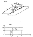
- FIG. 1 schematically shows the welding of a board or a tailored blanks, which is formed from the sheets 1 and 2, which butt along a joint line 3 blunt. It is usually flat sheet metal parts of different thickness and / or different sheet properties to an element, the board (Tailored Blank) connected. This element is usually formed late into a component, eg to a component for an automobile.
- a laser beam 6 from a laser beam source 5 is guided along the joint line 3 and welded together the sheets 1 and 2 and forms behind the weld 4. It is irrelevant whether the laser beam source 5 over stationary workpieces or whether the workpieces moved past a fixed laser become.
- the unit 7 comprises means for generating at least one light line, in particular a laser light line, substantially transverse to the course of the joint line 3.
- the course of the light line is detected by a camera to approach the joint line detect. This is basically known and need not be further explained here.
- the detected area is indicated in the figure with 8, which is not true to scale; the detected area can be eg 8x8 mm or 10x10 mm.
- the image of the unit 7 is delivered via a line 12 to the evaluation unit and control unit 11, which may also be separate units for evaluation and control, and accordingly, the position of the laser beam for accurate tracking of the joint 3 is controlled.
- a seam inspection unit 9 is provided.
- the area covered by this is, again not to scale and including, for example, also 8x8 mm or 10x10 mm, indicated as area 10 in the figure.
- the procedure is now such that, in particular for testing the weld seam 4, both the light-slit method is used and a gray scale image is recorded, wherein the gray-scale image is evaluated to detect the quality of the weld seam.
- This evaluation of the gray-scale image should in particular determine local imperfections such as porosity, small holes and missing welds.
- the unit 9 is designed to generate at least one light line transverse to the weld 4.
- the light line is preferably generated by a light-section laser with high optical power (eg from 50 mW to 100 mW laser diodes on a narrow line) to always bring enough light to the sensor in the unit 9 in the present different reflection properties of the surfaces, the picks up the light line.
- the sensor in the unit 9 for the light line is preferably a CMOS sensor or a CMOS camera.
- the exposure time of the camera sensor is preferably chosen so long that the reflected light of the laser line is averaged over a portion of the surface. The 3D measurement thus comes about over an area that is larger than the line width of the laser. .
- the flash exposure is as short as possible, the illumination time of the illumination being short in order to compensate for the motion blur
- welding seam moving relative to the unit 9 is smaller than one pixel.
- the lighting is preferably done with dark field lighting, possibly instead in the Bright field.
- the sensor for recording the gray level image is also a CMOS sensor and preferably the same sensor that also receives the laser line.
- an image is taken by means of only one sensor, in particular a CMOS sensor or a CMOS camera, each in short successive time periods, which includes both a gray value image of the weld seam and the image of the laser line.
- the distance of the image recordings is chosen so that an overlap of the object area, ie a complete recording of the seam, is guaranteed.
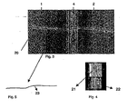
- FIG. 3 a corresponding image recording is shown, which shows the workpieces 1 and 2 and the weld 4, and the laser line 20th
- FIG. 1 schematically shows the receiving area 10, which is shown in enlarged scale in the figure, and is typically 10x10 mm or 8x8 mm, for example, in the laser welding of boards. For example, 60 frames per second are recorded for quality control during blank welding.
- the relative movement between the unit 9 or the CMOS camera and the weld seam 4 can be, for example, 500 mm / second.
- FIG. 2 shows a preferred characteristic, wherein on the X-axis, the intensity of the incident light on the sensor is shown and on the Y-axis, the corresponding response of the sensor and the sensor output signal as a bit value.
- the sensor output signal consists of a 10-bit word each. It can be seen that with a lower illuminance in the region A or within the distance ab on the X-axis, a linear characteristic 16 is provided.
- the sensor characteristic is not linear, preferably logarithmic. This allows the detection of the laser line even with large fluctuations in brightness or fluctuations in the reflection properties of the workpiece surfaces and the weld.
- the image of the laser line is output from the sensor in the range of 801-1024 of the 10-bit word.
- Two sensors can be provided which have the corresponding characteristic curves 16 or 17 and are arranged in the unit 9 in such a way that they essentially observe the same detection area 10.
- a single sensor which has an overall characteristic 18, which is composed of the characteristic sections 16 and 17.
- Such a sensor is available from Photonfocus AG, 8853 Lachen, Switzerland, on the market under the type designation MV-D1024 CL80.
- the characteristic curve of the sensor is thus adapted so that the scattered light of the flash illumination for the gray scale image detection lies in the lower linear range of the sensor response, which is preferably a dark field illumination; in the upper area lies the reflected light of the line laser.
- the properties of the sensor can be exploited in such a way that both types of lighting can be combined in one picture. By using only one sensor, the expenditure on equipment and the effort for the operator is lowered and also the maintenance effort.
- a color sensor can also be used. This may cause the separation of the representation In the image of the light line of the triangulation laser and the dark field illumination of the seam on the separation of the wavelengths of light can be further improved.
- the dark field illumination is preferably below 680 nm, the line laser above this wavelength.
- the images taken by the sensor are applied to an image evaluation unit 11.
- an image evaluation unit 11 There is, for example, a picture according to FIG. 3 before, wherein the image for the evaluation unit 11 must not be present in a visible representation, but only as a sequence of numbers. In this case, it is possible to operate in the unit 11 with 8-bit words.
- the separation of the grayscale values of the image can still take place in the 10-bit image, and the data can subsequently be transferred via corresponding tables (look-up tables) into the 8-bit areas 0-200 (for the grayscale image) and 200-255 (for the laser line).
- each image is carried out for the laser line in a conventional manner, wherein by means of the laser line, the cross profile of the seam can be determined, which is shown for explanation in Figure 5.
- the geometrical data of the seam e.g. Convexity, concavity and edge offset can be determined. These values are subject to ISO limits, compliance with which is recorded.
- the high-quality gray value image which is supplied by the unit 9, now also allows the assessment of the quality of the weld due to the evaluation of this image. For this purpose, in the image area, which represents the seam 4, the contours of the seam structure are highlighted.
- FIG. 4 this is shown for a seam portion, at 22 a processing step is shown where after dynamic binarization the seam structure is highlighted. In a further processing step according to region 21, the dynamically binarized Seam area skeletonized. Remain the contour lines of the seam structure.
- the corresponding image processing allows the detection of local defects, e.g. Porosity and small holes and missing fürschweissungen. On the one hand, this can be done by comparing the structures thus determined corresponding to regions 21 or 22 with known patterns of qualitatively good weld seams. It is also additionally or instead by the unit 11, the presence of the contour lines, their orientation or angular deviation from the seam longitudinal direction and / or their length are checked. In this way it is now possible to check the seam quality on the basis of a gray value image.
- the invention has been explained above with reference to a welding seam in board welding, but is not limited to this application.
- the quality of joints can be tested in this way, e.g. a spot weld or a bead of an adhesive.
- the invention can be used. All embodiments explained with reference to the unit 9 are hereby also indicated or adopted for the unit 7.
- the illumination and the image recording preferably also take place as explained with reference to the unit 9.
- the light line evaluation allows edge detection and the fat jump monitoring.
- the detection of the edge at zero gap / zero thickness jump and the measurement of the gap width is preferably done via the gray image evaluation.
- the preferred sensor configuration with a linear and logarithmic characteristic and the preferred illumination mode provides a qualitatively very good grayscale image with high resolution, large object field, large dynamic range despite high object speed, as was not the case in the prior art.
- the unit 7 is also connected via a line 12 to the image evaluation 11, as is the case with the line 14 for the unit 9.
- the laser source 5 is controlled or tracked by the unit 11 via the line 13 so that the welding by means of the laser beam takes place exactly at the location of the joint line 3.
- the unit 7 can perform the detection of edge damage in addition to the position detection, so perform the assessment of the quality of the joint before the joining step, as has been explained with reference to the unit 9. If the joint is an adhesive bead, the position and quality detection is likewise carried out by a unit corresponding to the unit 7 (or separated by two units) before the joining step.
Abstract
Description
Die Erfindung betrifft ein Verfahren gemäss Oberbegriff des Anspruchs 1 sowie eine Vorrichtung gemäss Oberbegriff des Anspruchs 10.The invention relates to a method according to the preamble of
Beim Zusammenfügen von Materialien, insbesondere durch Schweissung, aber auch Klebung, ergibt sich das Problem die Fügestelle zu erfassen. Dies sowohl bei punktförmigen Fügestellen (Punktschweissungen, Punktklebungen) als auch bei linienförmigen Fügestellen (Schweissnaht, Kleberraupe). Es kann sich dabei um eine Erfassung sowohl vor dem Fügeschritt als auch danach handeln, wobei unter Erfassung vorliegend einerseits die Erkennung der Lage und andererseits der Beschaffenheit bzw. Qualität der Fügestelle verstanden wird. So benötigen Schweissverfahren mit kleiner Wärmeeinflusszone (Strahlschweissen, insbesondere Laserstrahlschweissen), bei welchen die zusammenzufügenden Teile stumpf aneinanderstossen, ein Nahtführungssystem zur Erfassung der Lage der Fügestelle, um den Strahl beim Schweissen exakt der Trennlinie zwischen den Werkstückteilen folgen zu lassen. Besonders beim Schweissen von stumpf aneinandergrenzenden Blechen zu sogenannten Platinen oder tailored blanks ist eine sehr präzise Strahlführung notwendig, die auch bei exakt geschnittenen Platinenteilen, d.h. sehr geringem Spalt oder sogar geschlossenem Spalt zwischen den Werkstücken die Trennlinie erkennt. Dies sollte auch gewährleistet sein, wenn Blechteile gleicher Dicke miteinander verschweisst werden, so dass an der Trennlinie kein Dikkensprung auftritt, wie dies der Fall ist, wenn Bleche unterschiedlicher Dicke zusammengefügt werden. Es sollten ferner andererseits Kantenbeschädigungen der Teile erkannt werden, da eine qualitativ hochwertige Schweissnaht bei beschädigten Kanten nicht mehr möglich ist.When joining materials, in particular by welding, but also bonding, the problem arises to detect the joint. This applies both to punctiform joints (spot welds, point bonds) and to linear joints (weld seam, adhesive bead). It may be a detection both before the joining step and after act, wherein detection here on the one hand, the recognition of the situation and on the other hand, the nature or quality of the joint is understood. For example, welding processes with a small heat-affected zone (beam welding, in particular laser beam welding) in which the parts to be joined butt together, a seam guide system for detecting the position of the joint to allow the beam to follow during welding exactly the dividing line between the workpiece parts. Particularly when welding blunt adjacent plates to so-called blanks or tailored blanks a very precise beam guidance is necessary, which recognizes the parting line even with exactly cut platinum parts, ie very small gap or even closed gap between the workpieces. This should also be ensured when sheet metal parts of equal thickness with each other be welded, so that no Dikkensprung occurs at the dividing line, as is the case when sheets of different thickness are joined together. On the other hand, edge damage of the parts should also be recognized, since a high-quality weld with damaged edges is no longer possible.
Auch eine Bewertung der Fügestelle nach dem Fügeschritt, z.B. einer Schweissnaht auf deren Güte bzw. auf das Vorliegen von Schweissfehlern ist nach dem Fügen durchzuführen. Lasergeschweisste Platinen, die zu Formteilen verformt werden, und auch Rohre, insbesondere zur Innenhochdruckumformung vorgesehene Rohre aus Blechteilen, sogenannte tailored tubes, sollten einer 100 %igen Kontrolle der Schweissnaht unterzogen werden.Also an assessment of the joint after the joining step, e.g. A weld on its quality or on the presence of welding defects must be performed after joining. Laser-welded blanks, which are deformed into shaped parts, and also tubes, in particular tubes designed for hydroforming, made of sheet metal parts, so-called tailored tubes, should be subjected to a 100% control of the weld seam.
Die hohen Schweissgeschwindigkeiten und die Umgebungsbedingungen führen zum Einsatz von berührungslosen Erfassungseinrichtungen. Diese müssen die Kanten der zu schweissenden Platinen auch unter obigen Bedingungen zuverlässig erkennen, sowie den Kantenversatz und die Kantenqualität der Platinen überwachen; ferner müssen sie die geometrischen Daten wie Konvexität, Konkavität und Kantenversatz messen, um die Einhaltung der ISO Grenzwerte zu gewährleisten. Neben den geometrischen Daten sollen aber auch lokale Fehlstellen wie Porosität, kleine Löcher und fehlende Durchschweissungen gefunden werden, um die Qualität der Nähte sicherzustellen.The high welding speeds and the environmental conditions lead to the use of non-contact detection devices. These must reliably detect the edges of the boards to be welded, even under the above conditions, as well as monitor the edge offset and edge quality of the boards; they also need to measure geometric data such as convexity, concavity and edge offset to ensure compliance with ISO limits. In addition to the geometric data but also local defects such as porosity, small holes and missing Durchschweissungen be found to ensure the quality of the seams.
Zum Erkennen der Kanten bei der Lageerfassung ist es üblich, das sogenannte Lichtschnittverfahren anzuwenden, wobei ein Lichtstrahl, z.B. ein Laserstrahl, über die Fügelinie gelegt und dessen Versatz oder Richtungsänderung detektiert wird. In VDI Berichte Nr. 1572, 2000, P. Dillinger, A. Horn, K.-H. Noffz, Hochgeschwindigkeits-Geometrieerfassung beim Laserschweissen mittels FPGA Prozessoren, wird eine Laserlinie über eine Schweissnaht gelegt und mittels einer CMOS Kamera erfasst. Um Lichtschnitte in geringem Abstand zu legen und auszuwerten wird mit einer Bildwiederholrate von 500 Hz gearbeitet. Eine optische Kontrolle der Messfenster für die Laserlinien erfolgt mit einem Grauwertbild in Auflichtbeleuchtung, das aber nur streifenweise erzeugt wird und daher eine Bildwiederholrate von lediglich 16 Hz aufweist und, wie gesagt, nur zur Kontrolle des Lichtschnittprozesses dient.For detecting the edges in the position detection, it is customary to apply the so-called light section method, wherein a light beam, for example a laser beam, placed over the joint line and its offset or change of direction is detected. In VDI reports No. 1572, 2000, P. Dillinger, A. Horn, K.-H. Noffz, high-speed geometry acquisition in laser welding using FPGA processors, a laser line is placed over a weld seam and detected by means of a CMOS camera. In order to set and analyze light sections at a small distance, a refresh rate of 500 Hz is used. An optical control of the measurement window for the laser lines is done with a gray value image in reflected light illumination, which is generated only in strips and therefore has a refresh rate of only 16 Hz and, as I said, only serves to control the light-section process.
Bei einem kommerziell erhältlichen Sensorsystem zur Erkennung der Trennlinie stumpf aneinanderstossender Teile vor der Schweissstelle (TRUMPF-Nahtsensorik TNS, Fa. TRUMPF Lasertechnik GmbH) wird ein Lichtschnittprojektor und eine CCD-Kamera verwendet, wobei ebenfalls ein Videobild mit Auflichtbeleuchtung aufgenommen wird. Das Videobild wird nach Helligkeitssignal und dessen Ableitung ausgewertet, um die Position des Stumpfstosses zu ermitteln, was auch mit dem Lichtschnittverfahren erfolgen kann. Bei matten Werkstückoberflächen wird auch eine überlagerung von Auflichtbeleuchtung und Lichtschnittprojektion vorgeschlagen, so dass durch Grauwertbildauswertung die seitliche Position des Stumpfstosses und mittels Lichtschnittauswertung der Höhenversatz ermittelt werden kann. In
Die
Die
Die
Die
Die
Der Erfindung liegt zunächst die Aufgabe zugrunde ein verbessertes Verfahren zur Erfassung der Nahtqualität einer Schweißnaht zu schaffen.The invention is first based on the object to provide an improved method for detecting the seam quality of a weld.
Dies wird beim Verfahren der eingangs genannten Art dadurch erreicht, dass das Grauwertbild zur Beurteilung der Qualität der Schweißnaht ausgewertet wird.This is achieved in the method of the type mentioned in that the gray value image is evaluated to assess the quality of the weld.
Dadurch, dass neu das Grauwertbild nicht nur zur Lageerkennung herangezogen wird, sondern effektiv zur Qualitätskontrolle der Schweißnaht ausgewertet wird, ergibt sich eine verbesserte Kontrolle der Schweißnaht,The fact that the gray scale image is not only used for position detection, but is effectively evaluated for quality control of the weld, results in improved control of the weld,
Bei der Lageerkennung kann dabei das Grauwertbild zur Erkennung von Kantenbeschädigungen und zur Vermessung der Spaltbreite ausgewertet werden. Vorzugsweise wird das Verfahren indes nach dem Fügeschritt, besonders bei der Bewertung von Schweissnähten eingesetzt. Weiter ist es bevorzugt, wenn als Sensor eine CMOS Sensoranordnung, bevorzugt ein einziger CMOS Sensor, eingesetzt wird, die bzw. der bei niedriger Beleuchtungsstärke eine im wesentlichen lineare Kennlinie und bei höheren Beleuchtungsstärken eine davon abweichende Kennlinie, bevorzugt eine gekrümmte, allenfalls logarithmische Kennlinie aufweist, was die Aufnahme des Grauwertbildes mit dessen Beleuchtung, die vorzugsweise eine Dunkelfeldbeleuchtung ist, und des Lichtmusters des Lichtschnittverfahrens durch den Sensor bzw, die Separation dieser Mildteile bei der Auswertung deutlich verbessert. Anstelle oder zusätzlich zur Aufnahme eines Grauwertbildes kann ein Farbbild aufgenommen werden, was eine zusätzliche Separation aufgrund der verschiedenen Wellenlängen der beiden Lichtquellen ermöglicht. Die Auswertung erfolgt bevorzugterweise für die Schweissnahtqualität durch Ermittlung von Texturmerkmalen der Schweissnaht aus dem Bild, z.B. durch Analyse von Konturlinien. Ein Fehlen bestimmter Merkmale wird dabei z.B. als schlechte Qualität bewertet.In the case of position detection, the gray value image can be evaluated for detecting edge damage and for measuring the gap width. Preferably, however, the method is used after the joining step, especially in the evaluation of welds. Further, it is preferred if the sensor used is a CMOS sensor arrangement, preferably a single CMOS sensor, which has a substantially linear characteristic at low illuminance and a characteristic deviating therefrom at higher illuminances, preferably a curved, at best logarithmic characteristic what the recording of the gray value image with its illumination, which is preferably a dark field illumination, and the light pattern of the light section method by the sensor or, the separation of these mild parts significantly improved in the evaluation. Instead of or in addition to taking a halftone image, a color image can be recorded, which allows additional separation due to the different wavelengths of the two light sources. The evaluation is preferably carried out for the weld quality by determining texture features of the weld from the image, e.g. by analysis of contour lines. A lack of certain features is e.g. rated as poor quality.
Der Erfindung liegt weiter die Aufgabe zugrunde, eine Vorrichtung zur Bewertung von Schweißnähten zu schaffen.The invention is further based on the object to provide a device for the evaluation of welds.
Ferner liegt der Erfindung die Aufgabe zugrunde, die Lageerfassung der Fügestelle, insbesondere vor dem Fügeschritt, also beim Schweissen die Kantenerkennung zur Führung des Schweissstrahls zu verbessern und zu vereinfachen.Furthermore, the invention has for its object to improve the position detection of the joint, in particular before the joining step, ie when welding the edge detection for guiding the welding beam and simplify.
Diese Aufgabe werden durch das Verfahren gemäß Anspruch 1 sowie durch die Vorrichtung gemäß Anspruch 10 gelöst. Vorteilhafte Ausgestaltungen und Weiterbildungen der Erfindung sind in den Unteransprüchen dargelegt.This object is achieved by the method according to
Im folgenden werden Ausführungsbeispiele der Erfindung anhand der Zeichnungen näher erläutert. Dabei zeigt
-
Figur 1 -
Figur,2 die Kennlinie eines bevorzugt eingesetzten Sensors; -
Figur 3 -
Figur 4 Figur 5 schematisch das Querprofil der Schweissnaht, wie es mit dem Lichtschnittverfahren ermittelbar ist.
-
FIG. 1 schematically a view of a laser welding process in board welding; -
Figure 2 the characteristic of a preferred sensor used; -
FIG. 3 schematically the image taken by the sensor; -
FIG. 4 two different processed images of the image of the weld; and - FIG. 5 schematically shows the transverse profile of the weld seam, as can be determined with the light-section method.
Zur Erfassung der Nahtqualität der Schweissnaht 4 nach der Schweissung ist es üblich, nach dem Lichtschnittverfahren zu arbeiten, um die geometrischen Daten, wie z.B. Konvexität, Konkavität und kantenversatz zu messen. Dazu ist eine Nahtprüfungseinheit 9 vorgesehen. Der von dieser erfasste Bereich ist, wiederum nicht massstäblich und z.B. ebenfalls 8x8 mm oder 10x10 mm umfassend, als Bereich 10 in der Figur angedeutet.For detecting the seam quality of the
Gemäss der Erfindung wird nun so vorgegangen, dass, insbesondere zur Prüfung der Schweissnaht 4, sowohl das Lichtschnittverfahren eingesetzt wird als auch ein Grauwertbild aufgenommen wird, wobei das Grauwertbild zur Erkennung der Qualität der Schweissnaht ausgewertet wird. Diese Auswertung des Grauwertbildes soll insbesondere lokale Fehlstellen wie Porosität, kleine Löcher und fehlende Durchschweissungen ermitteln. Die Einheit 9 ist dazu zur Erzeugung mindestens einer Lichtlinie quer zur Schweissnaht 4 ausgestaltet. Die Lichtlinie wird dabei vorzugsweise von einem Lichtschnittlaser mit hoher optischer Leistung (z.B. von 50 mW bis 100 mW Laserdioden auf eine schmale Linie) erzeugt, um bei den vorliegenden unterschiedlichen Reflektionseigenschaften der Oberflächen immer genügend Licht auf den Sensor in der Einheit 9 zu bringen, der die Lichtlinie aufnimmt. Der Sensor in der Einheit 9 für die Lichtlinie ist dabei vorzugsweise ein CMOS-Sensor bzw. eine CMOS-Kamera. Bei Relativbewegung zwischen der zu erfassenden Fügestelle und der Einheit 9, wie das im gezeigten Beispiel von
Für die Aufnahme des Grauwertbildes, die im wesentlichen an der selben Stelle der Naht erfolgt, an der auch die Laserlinie über die Schweissnaht gelegt wird, erfolgt eine möglichst kurze Blitzlicht-Belichtung, wobei die Belichtungszeit der Beleuchtung kurz sein soll, um die Bewegungsunschärfe der sich in diesem Beispiel relativ zur Einheit 9 bewegenden Schweissnaht kleiner als ein Pixel zu halten. Die Beleuchtung erfolgt dabei bevorzugt mit Dunkelfeldbeleuchtung, allenfalls stattdessen im Hellfeld. Vorzugsweise ist der Sensor zur Aufnahme des Grauwertbildes ebenfalls ein CMOS-Sensor und bevorzugterweise derselbe Sensor, der auch die Laserlinie aufnimmt. Bevorzugterweise wird also mittels nur eines Sensors, insbesondere eines CMOS-Sensors bzw. einer CMOS-Kamera jeweils in kurz aufeinanderfolgenden Zeiträumen ein Bild aufgenommen, welches sowohl ein Grauwertbild der Schweissnaht wie auch das Bild der Laserlinie umfasst. Der Abstand der Bildaufnahmen ist so gewählt, dass eine Überdeckung des Objektbereichs, d.h. eine lückenlose Aufnahme der Naht, gewährleistet ist.For taking the gray value image, which takes place substantially at the same point of the seam on which the laser line is also placed over the weld seam, the flash exposure is as short as possible, the illumination time of the illumination being short in order to compensate for the motion blur In this example, welding seam moving relative to the
In
Die vom Sensor aufgenommenen Bilder werden auf eine Bildauswerteeinheit 11 gegeben. Dort liegt z.B. ein Bild gemäss
Die Auswertung jedes Bildes erfolgt dabei für die Laserlinie auf herkömmliche Weise, wobei mittels der Laserlinie das Querprofil der Naht ermittelbar ist, welches zur Erläuterung in Figur 5 dargestellt ist. Aus diesem Querprofil sind auf bekannte Weise die geometrischen Daten der Naht, wie z.B. Konvexität, Konkavität und Kantenversatz ermittelbar. Für diese Werte bestehen ISO-Grenzwerte, deren Einhaltung so erfasst wird. Das hochwertige Grauwertbild, welches von der Einheit 9 geliefert wird, ermöglicht nun neu auch die Beurteilung der Schweissqualität aufgrund der Auswertung dieses Bildes. Dazu werden im Bildbereich, der die Naht 4 darstellt, die Konturen der Nahtstruktur hervorgehoben.The evaluation of each image is carried out for the laser line in a conventional manner, wherein by means of the laser line, the cross profile of the seam can be determined, which is shown for explanation in Figure 5. From this cross-section, in a known manner, the geometrical data of the seam, e.g. Convexity, concavity and edge offset can be determined. These values are subject to ISO limits, compliance with which is recorded. The high-quality gray value image, which is supplied by the
In
Für diese Verarbeitungsschritte sind entsprechende Bildbearbeitungsprogramme bekannt. Bevorzugt wird ein bekanntes derartiges Programm der ehemaligen Firma Logical Vision, heute Coreco Imaging, St. Laurent, Quebec, Kanada, mit der Bezeichnung WiT. Verwendet wurde die Version 5.3.Corresponding image processing programs are known for these processing steps. Preferred is a known such program of the former company Logical Vision, now Coreco Imaging, St. Laurent, Quebec, Canada, called WiT. The version 5.3 was used.
Die entsprechende Bildbearbeitung erlaubt die Erkennung von lokalen Fehlstellen, z.B. Porosität und kleine Löcher und fehlende Durchschweissungen. Dies kann einerseits dadurch erfolgen, dass die so ermittelten Strukturen entsprechend den Bereichen 21 oder 22 mit bekannten Mustern von qualitativ guten Schweissnähten verglichen werden. Es kann auch zusätzlich oder stattdessen durch die Einheit 11 das Vorhandensein der Konturlinien, deren Orientierung bzw. Winkelabweichung von der Nahtlängsrichtung und/oder deren Länge geprüft werden. Auf diese Weise ist es nun möglich, die Nahtqualität aufgrund eines Grauwertbildes zu prüfen.The corresponding image processing allows the detection of local defects, e.g. Porosity and small holes and missing Durchschweissungen. On the one hand, this can be done by comparing the structures thus determined corresponding to
Bei der Aufnahme eines Farbbildes entsteht nach der Separation der Laserlinie über die Wellenlänge wieder ein Graubild. Die beschriebene Vorgehensweise zur Beurteilung der Schweissqualität bleibt gleich.When a color image is taken, a gray image is formed again after the separation of the laser line over the wavelength. The described procedure for assessing the welding quality remains the same.
Die Erfindung ist vorstehend anhand einer Schweissnaht beim Platinenschweissen erläutert worden, ist aber nicht auf diese Anwendung beschränkt. Es kann generell die Qualität von Fügestellen auf diese Weise geprüft werden, z.B. eine Punktschweissung oder auch eine Raupe eines Klebstoffes.The invention has been explained above with reference to a welding seam in board welding, but is not limited to this application. In general, the quality of joints can be tested in this way, e.g. a spot weld or a bead of an adhesive.
Auch bei der Kantenverfolgungseinheit 7 kann die Erfindung verwendet werden. Alle anhand der Einheit 9 erläuterten Ausgestaltungen sind dabei hiermit auch für die Einheit 7 angegeben bzw. übernommen. Dabei erfolgt - besonders die Beleuchtung und die Bildaufnahme bevorzugterweise ebenfalls so wie anhand der Einheit 9 erläutert. Die Lichtlinienauswertung erlaubt dabei die Kantenerkennung und die Dickensprung-Überwachung. Die Erkennung der Kante bei Null-Spalt/Null-Dickensprung und die Vermessung der Spaltbreite geschieht bevorzugterweise über die Graubildauswertung. Auch in diesem Fall steht durch die bevorzugte Sensorausgestaltung mit linearer und logarithmischer Kennlinie und die bevorzugte Beleuchtungsart ein qualitativ sehr gutes Grauwertbild mit hoher Auflösung, grossem Objektfeld, grossem Dynamikumfang trotz hoher Objektgeschwindigkeit zur Verfügung, wie dies nach Stand der Technik nicht der Fall war. Die Einheit 7 ist dabei ebenfalls über eine Leitung 12 mit der Bildauswertung 11 verbunden, wie dies mit der Leitung 14 für die Einheit 9 der Fall ist. In diesem Fall wird entsprechende dem Zweck der Einheit 7 die Laserquelle 5 durch die Einheit 11 über die Leitung 13 so gesteuert bzw. nachgeführt, dass die Schweissung mittels des Laserstrahls exakt an der Stelle der Fügelinie 3 erfolgt.Also in the
Der Einheit 7 kann dabei aber zusätzlich zu der Lageerkennung die Erfassung von Kantenschäden ausführen, also die Beurteilung der Qualität der Fügestelle vor dem Fügeschritt ausführen, wie dies anhand der Einheit 9 erläutert worden ist. Handelt es sich bei der Fügestelle um eine Klebstoffraupe, so erfolgt ebenfalls die Lage- und Qualitätserfassung durch eine Einheit entsprechend der Einheit 7 (oder getrennt durch zwei Einheiten) vor dem Fügeschritt.However, the
Claims (15)
- Method for detecting the seam quality of a welding seam (4) during the welding of workpieces (1, 2), in the case of which a light section method is used to record at least one light line (20) for detecting the three-dimensional course of the welding seam (4), characterized in that in addition a grey level image or a colour image of the welding seam (4) is recorded by a camera sensor of a seam testing unit (9) and the use of flashlight illumination, and in that the grey level image or colour image is evaluated to assess the quality of the welding seam (4), local defects of the welding seam (4) being determined.
- Method according to Claim 1, characterized in that the at least one light line (20) of the light section method and the grey level image or colour image are recorded together on one image.
- Method according to Claim 1 or 2, characterized in that the recording, which includes at least one light line (20) of the light section method which is generated by a laser, is performed by means of a nonlinear, logarithmic sensor characteristic, and in that the grey level image acquisition or colour image acquisition is performed by a sensor which has a substantially linear characteristic.
- Method according to Claim 3, characterized in that the substantially linear characteristic lies in a lower range of illuminance than does the nonlinear characteristic.
- Method according to Claim 3 or 4, characterized by the provision of only one sensor, which has a linear and a nonlinear characteristic section.
- Method according to one of Claims 1 to 5, characterized in that a relative movement takes place between the workpiece (1, 2) and recording device, and the exposure time for the at least one light line (20) is selected to be so long that the scattered light of the light line (20) is reflected by an area of the welding seam (4) which is wider than the light line (20).
- Method according to one of Claims 1 to 6, characterized in that a relative movement takes place between the workpiece (1, 2) and recording device, and the exposure time for the grey level image or colour image is selected by means of the flash illumination to be so short that the motion blur is kept smaller than one pixel.
- Method according to one of Claims 1 to 7, characterized in that printed circuit boards are welded as the workpieces (1, 2).
- Method according to one of Claims 1 to 8, characterized in that during the evaluation of the grey level image the contours of the structures of the welding seam (4) are highlighted and examined.
- Device for detecting the seam quality of a welding seam (4) during the welding of workpieces (1, 2), comprising a seam testing unit (9) having a light line projecting unit and a camera sensor for recording the light line (20) and an image, and having an image evaluation unit for the light line (20), characterized in that a flash illumination unit is provided for recording a grey level image or colour image by the camera sensor, and in that the image evaluation unit is configured to detect quality features of the welding seam (4) by determining local defects of the welding seam with the aid of the grey level image or colour image.
- Device according to Claim 10, characterized in that the camera sensor of the seam testing unit (9) is configured to record an image on which the light line (20) and the grey level image or colour image are recorded together.
- Device according to Claim 10 or 11, characterized in that the camera sensor of the seam testing unit (9) has a nonlinear, logarithmic sensor characteristic for the light line (20), and a substantially linear characteristic for the grey level image or colour image.
- Device according to one of Claims 10 to 12, characterized in that the seam testing unit (9) has a sensor which has a substantially linear characteristic section and a nonlinear characteristic section, the substantially linear characteristic section lying where the illumination sensitivity of the sensor is low.
- Device according to Claim 13, characterized in that the seam testing unit (9) has only one sensor, which is a CMOS sensor.
- Device according to one of Claims 10 to 14, characterized in that the image evaluation unit is configured to highlight and assess the contours of the welding seam area in the grey level image.
Applications Claiming Priority (3)
| Application Number | Priority Date | Filing Date | Title |
|---|---|---|---|
| CH21012001 | 2001-11-15 | ||
| CH210101 | 2001-11-15 | ||
| PCT/CH2002/000613 WO2003041902A1 (en) | 2001-11-15 | 2002-11-14 | Method and device for evaluation of jointing regions on workpieces |
Publications (2)
| Publication Number | Publication Date |
|---|---|
| EP1448334A1 EP1448334A1 (en) | 2004-08-25 |
| EP1448334B1 true EP1448334B1 (en) | 2011-04-20 |
Family
ID=4567514
Family Applications (1)
| Application Number | Title | Priority Date | Filing Date |
|---|---|---|---|
| EP02774233A Expired - Lifetime EP1448334B1 (en) | 2001-11-15 | 2002-11-14 | Method and device for detecting the quality of a welding seam during the welding of workpieces |
Country Status (10)
| Country | Link |
|---|---|
| US (1) | US7577285B2 (en) |
| EP (1) | EP1448334B1 (en) |
| JP (1) | JP4531396B2 (en) |
| KR (1) | KR100922478B1 (en) |
| AT (1) | ATE506138T1 (en) |
| CA (1) | CA2465231C (en) |
| DE (1) | DE50215016D1 (en) |
| ES (1) | ES2363078T3 (en) |
| PT (1) | PT1448334E (en) |
| WO (1) | WO2003041902A1 (en) |
Cited By (1)
| Publication number | Priority date | Publication date | Assignee | Title |
|---|---|---|---|---|
| EP4010145B1 (en) * | 2020-09-02 | 2023-10-18 | Precitec GmbH & Co. KG | Method for analyzing a workpiece surface for a laser machining process, and analysis device for analyzing a workpiece surface |
Families Citing this family (90)
| Publication number | Priority date | Publication date | Assignee | Title |
|---|---|---|---|---|
| US6627863B2 (en) * | 2000-12-15 | 2003-09-30 | Mitutoyo Corporation | System and methods to determine the settings of multiple light sources in a vision system |
| DE10361018C9 (en) * | 2003-12-23 | 2021-03-04 | QUISS Qualitäts-Inspektionssysteme und Service GmbH | Method for recognizing a structure to be applied to a substrate with a plurality of cameras and a device therefor |
| EA009923B1 (en) * | 2004-03-27 | 2008-04-28 | Тексмаг Гмбх | Apparatus for detecting joints in rubber sheets |
| CA2463409A1 (en) * | 2004-04-02 | 2005-10-02 | Servo-Robot Inc. | Intelligent laser joining head |
| WO2006128317A1 (en) * | 2005-06-03 | 2006-12-07 | Elpatronic Ag | Method for illumination, and illumination arrangement |
| KR101362006B1 (en) | 2005-11-14 | 2014-02-11 | 프리시텍 비전 게엠베하 운트 코. 카게 | Method and device for assessing joins of workpieces |
| KR100797239B1 (en) * | 2005-12-23 | 2008-01-23 | 주식회사 포스코 | Apparatus and method for on-line detecting welding part of strip |
| JP5357030B2 (en) * | 2006-09-06 | 2013-12-04 | プレシテック ヴィジョン ゲーエムベーハー ウント コンパニー カーゲー | Method and apparatus for optically determining weld quality during welding |
| JP5154134B2 (en) * | 2006-10-05 | 2013-02-27 | 株式会社キーエンス | Optical displacement meter, optical displacement measuring method, optical displacement measuring program |
| JP2008175577A (en) * | 2007-01-16 | 2008-07-31 | Jfe Steel Kk | Method and device for monitoring welded part of electro-resistance-welded pipe and manufacturing method of electro-resistance-welded pipe |
| DE102007024789B3 (en) * | 2007-05-26 | 2008-10-23 | Trumpf Werkzeugmaschinen Gmbh + Co. Kg | Method for detecting defects in a weld during a laser welding process |
| US7692800B2 (en) * | 2007-08-03 | 2010-04-06 | Siemens Medical Solutions Usa, Inc. | Multi-level light curtain with structure light sources and imaging sensors |
| FR2923295B1 (en) * | 2007-11-06 | 2009-12-11 | Areva Np | METHOD AND DEVICE FOR VISUALIZING AND CONTROLLING THE PROFILE OF A WELDING CORD WITHIN A CHAMFER MADE BETWEEN TWO METAL PIECES |
| WO2009146359A1 (en) | 2008-05-28 | 2009-12-03 | Illinois Tool Works Inc. | Welding training system |
| DE102008032509A1 (en) * | 2008-07-10 | 2010-01-14 | Epcos Ag | Heating device and method for producing the heating device |
| MX2011005336A (en) * | 2008-11-21 | 2011-10-14 | Precitec Kg | Method and device for monitoring a laser machining operation to be performed on a workpiece and laser machining head having such a device. |
| DE102009057209B4 (en) * | 2009-02-09 | 2012-06-28 | Scansonic Mi Gmbh | Device with scanner optics for material processing by laser |
| DE102009042986B3 (en) * | 2009-09-25 | 2011-03-03 | Precitec Kg | Welding head and method for joining a workpiece |
| DE102010030435A1 (en) | 2010-06-23 | 2011-12-29 | Carl Zeiss Smt Gmbh | metrology system |
| JP5672480B2 (en) * | 2010-08-30 | 2015-02-18 | スズキ株式会社 | Apparatus and method for determining shape of terminal end of bead |
| US8716627B2 (en) | 2010-09-10 | 2014-05-06 | Honeywell International Inc. | Welding systems and methods |
| DE102011104550B4 (en) * | 2011-06-17 | 2014-04-30 | Precitec Kg | Optical measuring device for monitoring a joint seam, joining head and laser welding head with the same |
| US9101994B2 (en) | 2011-08-10 | 2015-08-11 | Illinois Tool Works Inc. | System and device for welding training |
| US20130119040A1 (en) * | 2011-11-11 | 2013-05-16 | Lincoln Global, Inc. | System and method for adaptive fill welding using image capture |
| DE102012210012A1 (en) * | 2012-06-14 | 2013-12-19 | Bayerische Motoren Werke Aktiengesellschaft | Method and apparatus for laser remote welding of two coated sheets |
| WO2014026297A1 (en) * | 2012-08-15 | 2014-02-20 | Soutec Ag | Method for monitoring the edge position of two panels and use of the method |
| US9583014B2 (en) | 2012-11-09 | 2017-02-28 | Illinois Tool Works Inc. | System and device for welding training |
| US9808857B2 (en) | 2013-02-05 | 2017-11-07 | Comau Llc | Continuous fastener feeding apparatus and method |
| CN103134809B (en) * | 2013-03-14 | 2015-04-29 | 苏州华源包装股份有限公司 | Welded line defect detection method |
| US9713852B2 (en) | 2013-03-15 | 2017-07-25 | Illinois Tool Works Inc. | Welding training systems and devices |
| US9728103B2 (en) | 2013-03-15 | 2017-08-08 | Illinois Tool Works Inc. | Data storage and analysis for a welding training system |
| US9666100B2 (en) | 2013-03-15 | 2017-05-30 | Illinois Tool Works Inc. | Calibration devices for a welding training system |
| US9672757B2 (en) | 2013-03-15 | 2017-06-06 | Illinois Tool Works Inc. | Multi-mode software and method for a welding training system |
| US9583023B2 (en) | 2013-03-15 | 2017-02-28 | Illinois Tool Works Inc. | Welding torch for a welding training system |
| EP2805800B1 (en) * | 2013-05-22 | 2015-09-16 | FFT EDAG Produktionssysteme GmbH & Co. KG | Joining of a workpiece with concealed seam |
| US10480862B2 (en) | 2013-05-23 | 2019-11-19 | Crc-Evans Pipeline International, Inc. | Systems and methods for use in welding pipe segments of a pipeline |
| US10589371B2 (en) | 2013-05-23 | 2020-03-17 | Crc-Evans Pipeline International, Inc. | Rotating welding system and methods |
| US9821415B2 (en) | 2014-03-28 | 2017-11-21 | Crc-Evans Pipeline International, Inc. | Internal pipeline cooler |
| US10040141B2 (en) * | 2013-05-23 | 2018-08-07 | Crc-Evans Pipeline International, Inc. | Laser controlled internal welding machine for a pipeline |
| US10695876B2 (en) | 2013-05-23 | 2020-06-30 | Crc-Evans Pipeline International, Inc. | Self-powered welding systems and methods |
| US11767934B2 (en) | 2013-05-23 | 2023-09-26 | Crc-Evans Pipeline International, Inc. | Internally welded pipes |
| KR101481618B1 (en) * | 2013-09-03 | 2015-01-12 | 주식회사 포스코 | Apparatus and method for estimating welding quality of strip |
| US10056010B2 (en) | 2013-12-03 | 2018-08-21 | Illinois Tool Works Inc. | Systems and methods for a weld training system |
| US9589481B2 (en) * | 2014-01-07 | 2017-03-07 | Illinois Tool Works Inc. | Welding software for detection and control of devices and for analysis of data |
| US10105782B2 (en) | 2014-01-07 | 2018-10-23 | Illinois Tool Works Inc. | Feedback from a welding torch of a welding system |
| US9724788B2 (en) | 2014-01-07 | 2017-08-08 | Illinois Tool Works Inc. | Electrical assemblies for a welding system |
| US9751149B2 (en) | 2014-01-07 | 2017-09-05 | Illinois Tool Works Inc. | Welding stand for a welding system |
| US10170019B2 (en) | 2014-01-07 | 2019-01-01 | Illinois Tool Works Inc. | Feedback from a welding torch of a welding system |
| US9757819B2 (en) | 2014-01-07 | 2017-09-12 | Illinois Tool Works Inc. | Calibration tool and method for a welding system |
| US20150273604A1 (en) * | 2014-03-25 | 2015-10-01 | Comau Llc | Material joining inspection and repair |
| US10665128B2 (en) | 2014-06-27 | 2020-05-26 | Illinois Tool Works Inc. | System and method of monitoring welding information |
| US9937578B2 (en) | 2014-06-27 | 2018-04-10 | Illinois Tool Works Inc. | System and method for remote welding training |
| US9862049B2 (en) | 2014-06-27 | 2018-01-09 | Illinois Tool Works Inc. | System and method of welding system operator identification |
| US10307853B2 (en) | 2014-06-27 | 2019-06-04 | Illinois Tool Works Inc. | System and method for managing welding data |
| US9724787B2 (en) | 2014-08-07 | 2017-08-08 | Illinois Tool Works Inc. | System and method of monitoring a welding environment |
| US11014183B2 (en) | 2014-08-07 | 2021-05-25 | Illinois Tool Works Inc. | System and method of marking a welding workpiece |
| US9875665B2 (en) | 2014-08-18 | 2018-01-23 | Illinois Tool Works Inc. | Weld training system and method |
| CA2956318C (en) | 2014-08-29 | 2022-11-29 | Shankar Rajagopalan | Method and system for welding |
| US9545693B2 (en) * | 2014-10-07 | 2017-01-17 | Caterpillar Inc. | Consumable insert for welding |
| US11247289B2 (en) | 2014-10-16 | 2022-02-15 | Illinois Tool Works Inc. | Remote power supply parameter adjustment |
| US10239147B2 (en) | 2014-10-16 | 2019-03-26 | Illinois Tool Works Inc. | Sensor-based power controls for a welding system |
| US10210773B2 (en) | 2014-11-05 | 2019-02-19 | Illinois Tool Works Inc. | System and method for welding torch display |
| US10490098B2 (en) | 2014-11-05 | 2019-11-26 | Illinois Tool Works Inc. | System and method of recording multi-run data |
| US10204406B2 (en) * | 2014-11-05 | 2019-02-12 | Illinois Tool Works Inc. | System and method of controlling welding system camera exposure and marker illumination |
| US10373304B2 (en) | 2014-11-05 | 2019-08-06 | Illinois Tool Works Inc. | System and method of arranging welding device markers |
| US10417934B2 (en) | 2014-11-05 | 2019-09-17 | Illinois Tool Works Inc. | System and method of reviewing weld data |
| US10402959B2 (en) | 2014-11-05 | 2019-09-03 | Illinois Tool Works Inc. | System and method of active torch marker control |
| ES2753441T3 (en) | 2015-01-16 | 2020-04-08 | Comau Spa | Riveting apparatus |
| US10427239B2 (en) | 2015-04-02 | 2019-10-01 | Illinois Tool Works Inc. | Systems and methods for tracking weld training arc parameters |
| KR101703599B1 (en) * | 2015-07-31 | 2017-02-07 | 현대자동차 주식회사 | Roof laser brazing system |
| US10373517B2 (en) | 2015-08-12 | 2019-08-06 | Illinois Tool Works Inc. | Simulation stick welding electrode holder systems and methods |
| US10657839B2 (en) | 2015-08-12 | 2020-05-19 | Illinois Tool Works Inc. | Stick welding electrode holders with real-time feedback features |
| US10593230B2 (en) | 2015-08-12 | 2020-03-17 | Illinois Tool Works Inc. | Stick welding electrode holder systems and methods |
| US10438505B2 (en) | 2015-08-12 | 2019-10-08 | Illinois Tool Works | Welding training system interface |
| US10197987B2 (en) * | 2015-08-26 | 2019-02-05 | The Boeing Company | Use of manufacturing compounds to create fiducial marks |
| JP6439629B2 (en) * | 2015-08-28 | 2018-12-19 | トヨタ自動車株式会社 | Measurement method for welded parts |
| CN106514064A (en) * | 2015-09-15 | 2017-03-22 | 苏州中启维盛机器人科技有限公司 | Weld verification method |
| DE102016102492B4 (en) | 2016-02-12 | 2021-10-07 | Precitec Gmbh & Co. Kg | Method and device for monitoring a joint seam and laser processing head |
| US11458571B2 (en) | 2016-07-01 | 2022-10-04 | Crc-Evans Pipeline International, Inc. | Systems and methods for use in welding pipe segments of a pipeline |
| DE102017102762B4 (en) | 2017-02-13 | 2023-06-15 | Precitec Gmbh & Co. Kg | Method for detecting joining positions of workpieces and laser processing head with a device for carrying out this method |
| CN106735744B (en) * | 2017-03-14 | 2019-07-26 | 武汉豪岩照明电子有限公司 | Transistor oscillation path converts electric welding machine |
| US10831177B2 (en) * | 2017-06-23 | 2020-11-10 | General Electric Company | Systems and methods for automated welding |
| KR102020391B1 (en) * | 2017-09-25 | 2019-09-10 | 주식회사 포스코 | Apparatus of estimating welding quality |
| CN113615160B (en) * | 2019-03-20 | 2023-06-09 | 鲍勃斯脱梅克斯股份有限公司 | Multi-camera imaging system using laser lines |
| US11288978B2 (en) | 2019-07-22 | 2022-03-29 | Illinois Tool Works Inc. | Gas tungsten arc welding training systems |
| US11776423B2 (en) | 2019-07-22 | 2023-10-03 | Illinois Tool Works Inc. | Connection boxes for gas tungsten arc welding training systems |
| FR3108170B1 (en) * | 2020-03-12 | 2023-04-28 | Psa Automobiles Sa | Control gauge to control the position and dimensions of a bead of glue. |
| DE102020203983A1 (en) * | 2020-03-27 | 2021-09-30 | Trumpf Laser Gmbh | Method for OCT weld seam monitoring as well as the associated laser processing machine and computer program product |
| DE102021002917A1 (en) | 2021-06-07 | 2021-07-22 | Daimler Ag | Procedure for testing weld seams |
| CN115980092B (en) * | 2023-03-20 | 2023-06-23 | 宁波吉宁汽车零部件有限公司 | Welding part detection equipment |
Family Cites Families (48)
| Publication number | Priority date | Publication date | Assignee | Title |
|---|---|---|---|---|
| US3005912A (en) * | 1955-04-04 | 1961-10-24 | Union Tank Car Co | Method of producing visual standards and article produced |
| US3345563A (en) * | 1963-07-01 | 1967-10-03 | American Mach & Foundry | Method and apparatus for measuring true discontinuities in members of varying thickness by compensating for the effect of thickness on such measurements |
| US4242702A (en) * | 1976-12-01 | 1980-12-30 | Hitachi, Ltd. | Apparatus for automatically checking external appearance of object |
| JPS5542185A (en) * | 1978-09-22 | 1980-03-25 | Kawasaki Heavy Ind Ltd | Detecting device for arc welding or the like |
| US4305096A (en) * | 1980-02-26 | 1981-12-08 | Kabushiki Kaisha Komatsu Seisakusho | Method of detecting weld lines |
| US4410787A (en) * | 1981-08-31 | 1983-10-18 | Sri International | Image acquisition apparatus and process |
| US4567348A (en) * | 1983-01-25 | 1986-01-28 | The United States Of America As Represented By The Administrator Of The National Aeronautics And Space Administration | Automated weld torch guidance control system |
| JPS60128304A (en) * | 1983-12-15 | 1985-07-09 | Nippon Tsushin Gijutsu Kk | Measuring head of welding machine |
| US4863268A (en) * | 1984-02-14 | 1989-09-05 | Diffracto Ltd. | Diffractosight improvements |
| US4854724A (en) * | 1984-07-09 | 1989-08-08 | Lockheed Corporation | Method of and apparatus for thermographic evaluation of spot welds |
| US4591689A (en) * | 1985-02-25 | 1986-05-27 | Caterpillar Tractor Co. | Adaptive welding guidance apparatus |
| US4734766A (en) * | 1985-08-19 | 1988-03-29 | Kawasaki Steel Corporation | Method and system for locating and inspecting seam weld in metal seam-welded pipe |
| EP0275322B1 (en) * | 1986-07-15 | 1993-07-07 | Kabushiki Kaisha Yaskawa Denki Seisakusho | Method of detecting position data in arc welding |
| US4806732A (en) * | 1987-05-14 | 1989-02-21 | Caterpillar Inc. | Multi-power laser seam tracking system |
| US4877940A (en) * | 1987-06-30 | 1989-10-31 | Iit Research Institute | Using infrared imaging to monitor and control welding |
| US4849679A (en) * | 1987-12-31 | 1989-07-18 | Westinghouse Electric Corp. | Image processing system for an optical seam tracker |
| US4833381A (en) * | 1987-12-31 | 1989-05-23 | Westinghouse Electric Corp. | Optical automatic seam tracker and real time control system for an industrial robot |
| US5039868A (en) * | 1988-11-24 | 1991-08-13 | Omron Corporation | Method of and apparatus for inspecting printed circuit boards and the like |
| US4922174A (en) * | 1989-03-20 | 1990-05-01 | United Technologies Corporation | Seam tracking between mating parts |
| US5078496A (en) * | 1990-08-14 | 1992-01-07 | Autospect, Inc. | Machine vision surface characterization system |
| US5150175A (en) * | 1991-03-13 | 1992-09-22 | American Research Corporation Of Virginia | Optical imaging system for fabric seam detection |
| US5189514A (en) * | 1991-08-29 | 1993-02-23 | General Dynamics Corporation Convair Division | Guidance system for automatic riveters |
| JP3123146B2 (en) * | 1991-09-11 | 2001-01-09 | トヨタ自動車株式会社 | Weld bead quality inspection equipment |
| US5275327A (en) * | 1992-10-13 | 1994-01-04 | Eg&G Idaho, Inc. | Integrated optical sensor |
| DE4312241A1 (en) * | 1993-04-15 | 1994-10-20 | Deutsche Aerospace | Method for measuring welds (seams, welded seams) |
| EP0655294B1 (en) * | 1993-11-30 | 1997-05-02 | Elpatronic Ag | Process for simultaneously measuring temperatures in a laser seam welding using at least two pyrometers and process parameters treatment and seam quality control |
| DE4408226C2 (en) | 1994-03-11 | 1997-08-28 | Peter Dr Ing Lehmann | Measuring device for the process-related determination of the roughness of technical surfaces by evaluating di- or polychromatic speckle patterns |
| FI97646C (en) * | 1994-10-19 | 1997-01-27 | Kvaerner Masa Yards Oy | Equipment for inspecting welded plate assemblies |
| US5614116A (en) * | 1994-10-31 | 1997-03-25 | United Technologies Corporation | Welding control using fuzzy logic analysis of video imaged puddle dimensions |
| JPH08166813A (en) * | 1994-12-14 | 1996-06-25 | Fanuc Ltd | Tracking control method for robot accompanied by weaving operation |
| EP0770445B1 (en) * | 1995-10-06 | 2001-11-07 | Elpatronic Ag | Control and positioning method of a beam or jet for machining a workpiece |
| EP0822389B1 (en) | 1996-07-29 | 2003-04-16 | Elpatronic Ag | Procedure and device to determine and to verify the contour of a rim |
| EP0836093B1 (en) | 1996-10-10 | 2004-02-18 | Elpatronic Ag | Method and apparatus for optical weld inspection |
| KR100200204B1 (en) * | 1996-11-18 | 1999-06-15 | 윤종용 | Vision treatment and vision sensor for auto arc welder |
| US6920238B1 (en) * | 1996-12-03 | 2005-07-19 | Synchrotronics, Co. | Precision imaging system |
| CA2322531A1 (en) * | 1998-03-02 | 1999-09-10 | Elpatronic Ag | Testing a weld seam |
| JPH11264761A (en) * | 1998-03-18 | 1999-09-28 | Honda Motor Co Ltd | Optical sensor circuit and image sensor using the same |
| US6175107B1 (en) * | 1998-05-27 | 2001-01-16 | Owens-Brockway Glass Container Inc. | Inspection of containers employing a single area array sensor and alternately strobed light sources |
| DE19852302A1 (en) * | 1998-11-12 | 2000-05-25 | Fraunhofer Ges Forschung | Method and device for processing workpieces with high-energy radiation |
| US6024273A (en) * | 1998-12-04 | 2000-02-15 | Caterpillar Inc. | Method and system for determining weld bead quality |
| US6204469B1 (en) * | 1999-03-04 | 2001-03-20 | Honda Giken Kogyo Kabushiki Kaisha | Laser welding system |
| US6563575B1 (en) * | 1999-08-10 | 2003-05-13 | Automated Technology Services, Inc. | Optical sensing system for detecting welds and defects in metal |
| US6299050B1 (en) * | 2000-02-24 | 2001-10-09 | Hitachi, Ltd. | Friction stir welding apparatus and method |
| JP2001287064A (en) * | 2000-04-10 | 2001-10-16 | Ishikawajima Harima Heavy Ind Co Ltd | Visualizing device for laser beam welded zone |
| JP3385363B2 (en) * | 2000-05-11 | 2003-03-10 | 北海道大学長 | Laser welding method, laser welding apparatus, and gas shield apparatus for laser welding |
| FR2811427B1 (en) * | 2000-07-06 | 2002-10-25 | Aerospatiale Matra Ccr | METHOD FOR DETECTION AND IDENTIFICATION OF DEFECTS IN A WELDING CORD MADE BY LASER BEAM |
| US6900410B2 (en) * | 2001-02-01 | 2005-05-31 | National Institute For Materials Science | Laser welding processed |
| DE10158095B4 (en) * | 2001-05-05 | 2012-03-22 | Lpkf Laser & Electronics Ag | Device for controlling a weld in a workpiece made of weldable plastic |
-
2002
- 2002-11-14 WO PCT/CH2002/000613 patent/WO2003041902A1/en active Application Filing
- 2002-11-14 ES ES02774233T patent/ES2363078T3/en not_active Expired - Lifetime
- 2002-11-14 PT PT02774233T patent/PT1448334E/en unknown
- 2002-11-14 EP EP02774233A patent/EP1448334B1/en not_active Expired - Lifetime
- 2002-11-14 DE DE50215016T patent/DE50215016D1/en not_active Expired - Lifetime
- 2002-11-14 US US10/495,720 patent/US7577285B2/en active Active
- 2002-11-14 JP JP2003543775A patent/JP4531396B2/en not_active Expired - Fee Related
- 2002-11-14 CA CA2465231A patent/CA2465231C/en not_active Expired - Lifetime
- 2002-11-14 KR KR1020047007212A patent/KR100922478B1/en active IP Right Grant
- 2002-11-14 AT AT02774233T patent/ATE506138T1/en active
Cited By (1)
| Publication number | Priority date | Publication date | Assignee | Title |
|---|---|---|---|---|
| EP4010145B1 (en) * | 2020-09-02 | 2023-10-18 | Precitec GmbH & Co. KG | Method for analyzing a workpiece surface for a laser machining process, and analysis device for analyzing a workpiece surface |
Also Published As
| Publication number | Publication date |
|---|---|
| PT1448334E (en) | 2011-06-28 |
| US7577285B2 (en) | 2009-08-18 |
| JP2005508759A (en) | 2005-04-07 |
| KR20050044429A (en) | 2005-05-12 |
| US20050041852A1 (en) | 2005-02-24 |
| CA2465231C (en) | 2011-08-09 |
| ES2363078T3 (en) | 2011-07-20 |
| CA2465231A1 (en) | 2003-05-22 |
| EP1448334A1 (en) | 2004-08-25 |
| WO2003041902A1 (en) | 2003-05-22 |
| JP4531396B2 (en) | 2010-08-25 |
| DE50215016D1 (en) | 2011-06-01 |
| KR100922478B1 (en) | 2009-10-21 |
| ATE506138T1 (en) | 2011-05-15 |
Similar Documents
| Publication | Publication Date | Title |
|---|---|---|
| EP1448334B1 (en) | Method and device for detecting the quality of a welding seam during the welding of workpieces | |
| EP1949026B1 (en) | Method and device for assessing joins of workpieces | |
| DE102011104550B4 (en) | Optical measuring device for monitoring a joint seam, joining head and laser welding head with the same | |
| DE102013017795C5 (en) | Process monitoring method and apparatus | |
| EP3414042B1 (en) | Method and device for monitoring a joining seam during joining by means of a laser beam | |
| EP1904260B1 (en) | Method and device for determining the lateral relative displacement between a processing head and a workpiece | |
| DE102009042986B3 (en) | Welding head and method for joining a workpiece | |
| DE19716293C2 (en) | Device for regulating the focus position during laser beam welding | |
| EP2567773B1 (en) | Method for inspecting seam quality during a laser welding process | |
| EP2061621B1 (en) | Method and device for the optical assessment of welding quality during welding | |
| EP2726244B1 (en) | Method of detecting defects in a non-linear weld seam or a non-linear cutting gap during a laser-machining process ; corresponding laser-machining device | |
| DE10335501A1 (en) | Process, for welding or cutting workpieces along a predetermined edge, comprises optically acquiring and evaluating a process site using a dynamic screening unit | |
| DE102009050784B4 (en) | Method for image-based control of machining processes and method for repairing defects on workpieces | |
| DE102006018558A1 (en) | Device for automatically applying or generating and monitoring a structure applied to a substrate with determination of geometrical dimensions and a corresponding method therefor | |
| DE102013008085B4 (en) | Method and device for joining workpieces with a machining beam | |
| DE102020112116A1 (en) | Method for analyzing a laser machining process, system for analyzing a laser machining process and laser machining system with such a system | |
| DE102013112244A1 (en) | Apparatus and method for beam joining | |
| DE102008047140B4 (en) | Device and method for controlling the seam position during laser welding of butt joints and their use | |
| EP4010145B1 (en) | Method for analyzing a workpiece surface for a laser machining process, and analysis device for analyzing a workpiece surface | |
| DE19505832C2 (en) | Optical test facility for online evaluation of welds or soldered seams | |
| DE102008051459B4 (en) | Device for measuring geometric data of a body | |
| DE102017010108A1 (en) | Device and method for detecting the current position of a welding wire supplied to a laser welding process | |
| DE102017102762B4 (en) | Method for detecting joining positions of workpieces and laser processing head with a device for carrying out this method |
Legal Events
| Date | Code | Title | Description |
|---|---|---|---|
| PUAI | Public reference made under article 153(3) epc to a published international application that has entered the european phase |
Free format text: ORIGINAL CODE: 0009012 |
|
| 17P | Request for examination filed |
Effective date: 20040615 |
|
| AK | Designated contracting states |
Kind code of ref document: A1 Designated state(s): AT BE BG CH CY CZ DE DK EE ES FI FR GB GR IE IT LI LU MC NL PT SE SK TR |
|
| AX | Request for extension of the european patent |
Extension state: AL LT LV MK RO SI |
|
| RIN1 | Information on inventor provided before grant (corrected) |
Inventor name: HALSCHKA, MARTIN Inventor name: SCHWARZ, JOACHIM |
|
| RAP1 | Party data changed (applicant data changed or rights of an application transferred) |
Owner name: PRECITEC VISION GMBH & CO. KG |
|
| 17Q | First examination report despatched |
Effective date: 20090330 |
|
| GRAP | Despatch of communication of intention to grant a patent |
Free format text: ORIGINAL CODE: EPIDOSNIGR1 |
|
| RTI1 | Title (correction) |
Free format text: METHOD AND DEVICE FOR DETECTING THE QUALITY OF A WELDING SEAM DURING THE WELDING OF WORKPIECES. |
|
| GRAS | Grant fee paid |
Free format text: ORIGINAL CODE: EPIDOSNIGR3 |
|
| GRAA | (expected) grant |
Free format text: ORIGINAL CODE: 0009210 |
|
| AK | Designated contracting states |
Kind code of ref document: B1 Designated state(s): AT BE BG CH CY CZ DE DK EE ES FI FR GB GR IE IT LI LU MC NL PT SE SK TR |
|
| REG | Reference to a national code |
Ref country code: GB Ref legal event code: FG4D Free format text: NOT ENGLISH |
|
| REG | Reference to a national code |
Ref country code: CH Ref legal event code: EP Ref country code: CH Ref legal event code: NV Representative=s name: BOHEST AG |
|
| REG | Reference to a national code |
Ref country code: IE Ref legal event code: FG4D Free format text: LANGUAGE OF EP DOCUMENT: GERMAN |
|
| REF | Corresponds to: |
Ref document number: 50215016 Country of ref document: DE Date of ref document: 20110601 Kind code of ref document: P |
|
| REG | Reference to a national code |
Ref country code: DE Ref legal event code: R096 Ref document number: 50215016 Country of ref document: DE Effective date: 20110601 |
|
| REG | Reference to a national code |
Ref country code: PT Ref legal event code: SC4A Free format text: AVAILABILITY OF NATIONAL TRANSLATION Effective date: 20110614 |
|
| REG | Reference to a national code |
Ref country code: ES Ref legal event code: FG2A Ref document number: 2363078 Country of ref document: ES Kind code of ref document: T3 Effective date: 20110720 |
|
| REG | Reference to a national code |
Ref country code: SE Ref legal event code: TRGR |
|
| REG | Reference to a national code |
Ref country code: NL Ref legal event code: VDEP Effective date: 20110420 |
|
| REG | Reference to a national code |
Ref country code: IE Ref legal event code: FD4D |
|
| PG25 | Lapsed in a contracting state [announced via postgrant information from national office to epo] |
Ref country code: FI Free format text: LAPSE BECAUSE OF FAILURE TO SUBMIT A TRANSLATION OF THE DESCRIPTION OR TO PAY THE FEE WITHIN THE PRESCRIBED TIME-LIMIT Effective date: 20110420 Ref country code: GR Free format text: LAPSE BECAUSE OF FAILURE TO SUBMIT A TRANSLATION OF THE DESCRIPTION OR TO PAY THE FEE WITHIN THE PRESCRIBED TIME-LIMIT Effective date: 20110721 Ref country code: CY Free format text: LAPSE BECAUSE OF FAILURE TO SUBMIT A TRANSLATION OF THE DESCRIPTION OR TO PAY THE FEE WITHIN THE PRESCRIBED TIME-LIMIT Effective date: 20110420 |
|
| PG25 | Lapsed in a contracting state [announced via postgrant information from national office to epo] |
Ref country code: NL Free format text: LAPSE BECAUSE OF FAILURE TO SUBMIT A TRANSLATION OF THE DESCRIPTION OR TO PAY THE FEE WITHIN THE PRESCRIBED TIME-LIMIT Effective date: 20110420 |
|
| PG25 | Lapsed in a contracting state [announced via postgrant information from national office to epo] |
Ref country code: EE Free format text: LAPSE BECAUSE OF FAILURE TO SUBMIT A TRANSLATION OF THE DESCRIPTION OR TO PAY THE FEE WITHIN THE PRESCRIBED TIME-LIMIT Effective date: 20110420 Ref country code: IE Free format text: LAPSE BECAUSE OF FAILURE TO SUBMIT A TRANSLATION OF THE DESCRIPTION OR TO PAY THE FEE WITHIN THE PRESCRIBED TIME-LIMIT Effective date: 20110420 |
|
| PLBE | No opposition filed within time limit |
Free format text: ORIGINAL CODE: 0009261 |
|
| STAA | Information on the status of an ep patent application or granted ep patent |
Free format text: STATUS: NO OPPOSITION FILED WITHIN TIME LIMIT |
|
| PG25 | Lapsed in a contracting state [announced via postgrant information from national office to epo] |
Ref country code: SK Free format text: LAPSE BECAUSE OF FAILURE TO SUBMIT A TRANSLATION OF THE DESCRIPTION OR TO PAY THE FEE WITHIN THE PRESCRIBED TIME-LIMIT Effective date: 20110420 Ref country code: DK Free format text: LAPSE BECAUSE OF FAILURE TO SUBMIT A TRANSLATION OF THE DESCRIPTION OR TO PAY THE FEE WITHIN THE PRESCRIBED TIME-LIMIT Effective date: 20110420 |
|
| 26N | No opposition filed |
Effective date: 20120123 |
|
| REG | Reference to a national code |
Ref country code: DE Ref legal event code: R097 Ref document number: 50215016 Country of ref document: DE Effective date: 20120123 |
|
| PG25 | Lapsed in a contracting state [announced via postgrant information from national office to epo] |
Ref country code: MC Free format text: LAPSE BECAUSE OF NON-PAYMENT OF DUE FEES Effective date: 20111130 |
|
| REG | Reference to a national code |
Ref country code: AT Ref legal event code: MM01 Ref document number: 506138 Country of ref document: AT Kind code of ref document: T Effective date: 20111114 |
|
| PG25 | Lapsed in a contracting state [announced via postgrant information from national office to epo] |
Ref country code: AT Free format text: LAPSE BECAUSE OF NON-PAYMENT OF DUE FEES Effective date: 20111114 |
|
| PG25 | Lapsed in a contracting state [announced via postgrant information from national office to epo] |
Ref country code: LU Free format text: LAPSE BECAUSE OF NON-PAYMENT OF DUE FEES Effective date: 20111114 |
|
| PG25 | Lapsed in a contracting state [announced via postgrant information from national office to epo] |
Ref country code: BG Free format text: LAPSE BECAUSE OF FAILURE TO SUBMIT A TRANSLATION OF THE DESCRIPTION OR TO PAY THE FEE WITHIN THE PRESCRIBED TIME-LIMIT Effective date: 20110720 |
|
| REG | Reference to a national code |
Ref country code: CH Ref legal event code: PCAR Free format text: NEW ADDRESS: HOLBEINSTRASSE 36-38, 4051 BASEL (CH) |
|
| REG | Reference to a national code |
Ref country code: FR Ref legal event code: PLFP Year of fee payment: 14 |
|
| REG | Reference to a national code |
Ref country code: FR Ref legal event code: PLFP Year of fee payment: 15 |
|
| REG | Reference to a national code |
Ref country code: FR Ref legal event code: PLFP Year of fee payment: 16 |
|
| PGFP | Annual fee paid to national office [announced via postgrant information from national office to epo] |
Ref country code: TR Payment date: 20201111 Year of fee payment: 19 |
|
| PGFP | Annual fee paid to national office [announced via postgrant information from national office to epo] |
Ref country code: ES Payment date: 20201214 Year of fee payment: 19 Ref country code: PT Payment date: 20201105 Year of fee payment: 19 Ref country code: SE Payment date: 20201123 Year of fee payment: 19 Ref country code: IT Payment date: 20201130 Year of fee payment: 19 Ref country code: DE Payment date: 20201126 Year of fee payment: 19 Ref country code: FR Payment date: 20201120 Year of fee payment: 19 Ref country code: CZ Payment date: 20201105 Year of fee payment: 19 Ref country code: CH Payment date: 20201124 Year of fee payment: 19 Ref country code: GB Payment date: 20201123 Year of fee payment: 19 |
|
| PGFP | Annual fee paid to national office [announced via postgrant information from national office to epo] |
Ref country code: BE Payment date: 20201119 Year of fee payment: 19 |
|
| REG | Reference to a national code |
Ref country code: DE Ref legal event code: R119 Ref document number: 50215016 Country of ref document: DE |
|
| PG25 | Lapsed in a contracting state [announced via postgrant information from national office to epo] |
Ref country code: TR Free format text: LAPSE BECAUSE OF NON-PAYMENT OF DUE FEES Effective date: 20211114 |
|
| REG | Reference to a national code |
Ref country code: CH Ref legal event code: PL |
|
| GBPC | Gb: european patent ceased through non-payment of renewal fee |
Effective date: 20211114 |
|
| PG25 | Lapsed in a contracting state [announced via postgrant information from national office to epo] |
Ref country code: SE Free format text: LAPSE BECAUSE OF NON-PAYMENT OF DUE FEES Effective date: 20211115 Ref country code: PT Free format text: LAPSE BECAUSE OF NON-PAYMENT OF DUE FEES Effective date: 20220516 Ref country code: CZ Free format text: LAPSE BECAUSE OF NON-PAYMENT OF DUE FEES Effective date: 20211114 Ref country code: BE Free format text: LAPSE BECAUSE OF NON-PAYMENT OF DUE FEES Effective date: 20211130 |
|
| REG | Reference to a national code |
Ref country code: BE Ref legal event code: MM Effective date: 20211130 |
|
| PG25 | Lapsed in a contracting state [announced via postgrant information from national office to epo] |
Ref country code: LI Free format text: LAPSE BECAUSE OF NON-PAYMENT OF DUE FEES Effective date: 20211130 Ref country code: CH Free format text: LAPSE BECAUSE OF NON-PAYMENT OF DUE FEES Effective date: 20211130 |
|
| PG25 | Lapsed in a contracting state [announced via postgrant information from national office to epo] |
Ref country code: GB Free format text: LAPSE BECAUSE OF NON-PAYMENT OF DUE FEES Effective date: 20211114 Ref country code: DE Free format text: LAPSE BECAUSE OF NON-PAYMENT OF DUE FEES Effective date: 20220601 |
|
| PG25 | Lapsed in a contracting state [announced via postgrant information from national office to epo] |
Ref country code: FR Free format text: LAPSE BECAUSE OF NON-PAYMENT OF DUE FEES Effective date: 20211130 |
|
| PG25 | Lapsed in a contracting state [announced via postgrant information from national office to epo] |
Ref country code: PT Free format text: LAPSE BECAUSE OF EXPIRATION OF PROTECTION Effective date: 20221123 Ref country code: IT Free format text: LAPSE BECAUSE OF NON-PAYMENT OF DUE FEES Effective date: 20211114 |
|
| REG | Reference to a national code |
Ref country code: ES Ref legal event code: FD2A Effective date: 20230210 |
|
| PG25 | Lapsed in a contracting state [announced via postgrant information from national office to epo] |
Ref country code: ES Free format text: LAPSE BECAUSE OF NON-PAYMENT OF DUE FEES Effective date: 20211115 |