EP1447252A2 - Vormontierte Führungsschiene für Fahrzeugrollos, Rollo, Montageverfahren und entsprechendes Fahrzeug - Google Patents
Vormontierte Führungsschiene für Fahrzeugrollos, Rollo, Montageverfahren und entsprechendes Fahrzeug Download PDFInfo
- Publication number
- EP1447252A2 EP1447252A2 EP04364010A EP04364010A EP1447252A2 EP 1447252 A2 EP1447252 A2 EP 1447252A2 EP 04364010 A EP04364010 A EP 04364010A EP 04364010 A EP04364010 A EP 04364010A EP 1447252 A2 EP1447252 A2 EP 1447252A2
- Authority
- EP
- European Patent Office
- Prior art keywords
- vehicle
- clip
- guide rail
- rail
- fixing portion
- Prior art date
- Legal status (The legal status is an assumption and is not a legal conclusion. Google has not performed a legal analysis and makes no representation as to the accuracy of the status listed.)
- Withdrawn
Links
Images
Classifications
-
- B—PERFORMING OPERATIONS; TRANSPORTING
- B60—VEHICLES IN GENERAL
- B60J—WINDOWS, WINDSCREENS, NON-FIXED ROOFS, DOORS, OR SIMILAR DEVICES FOR VEHICLES; REMOVABLE EXTERNAL PROTECTIVE COVERINGS SPECIALLY ADAPTED FOR VEHICLES
- B60J1/00—Windows; Windscreens; Accessories therefor
- B60J1/20—Accessories, e.g. wind deflectors, blinds
- B60J1/2011—Blinds; curtains or screens reducing heat or light intensity
- B60J1/2013—Roller blinds
- B60J1/2036—Roller blinds characterised by structural elements
- B60J1/2052—Guides
Definitions
- the field of the invention is that of blinds, in particular for vehicles automobile. More specifically, the invention relates to blinds with removable screens, intended to be deployed to conceal a non-rectangular bay, and circulating in a slot, formed for example in the rear shelf of a vehicle, or in a case provided for this purpose.
- the invention relates in particular to roller blinds, but other canvas folding modes can, of course, be implemented (such as example a folding of the fabric according to preformed folds).
- a roller blind has a canvas, or curtain, forming screen, in the deployed position, in front of a bay window.
- the canvas is likely to be unrolled or wound through a slot in the interior trim or the rear shelf of a vehicle.
- One end of the fabric is mounted on a roller, or tube reel, mobile in rotation.
- the other end of the canvas has a bar draw.
- the bar draw is secured to two pads connected or mounted at its ends, and which run in rails to guide the draw bar, and therefore the canvas concealment, between its deployed position and its folded position.
- This displacement can be manual or motorized.
- the motor vehicle must of course be equipped with rails which will guide and maintain the skates (and more generally of all element capable of sliding in a rail, such as for example casters).
- the bottom of the rail is pierced with a few openings that allow the passage of screws.
- the establishment therefore requires a adjustment by trial and error, until the fitter succeeds in making coincide the opening made in the rail with a corresponding opening provided in the sheet. He must then hold the rail without moving, then insert the screw, and finally the screw, with a tool penetrating inside the rail.
- these operations are not easy, in particular by recalling that the space available for the fitter is very limited inside the vehicle.
- the invention in particular aims to overcome these drawbacks of the art prior.
- an objective of the invention is to provide a technique allowing a quick and easy installation and fastening of a rail blind guidance on a motor vehicle.
- Another object of the invention is to provide such a technique, which is inexpensive, both during the manufacture of the rail and during its assembly.
- Yet another objective of the invention is to provide the manufacturer automotive a technique simplifying the assembly ranges and the number of parts to be handled.
- a guide rail pre-equipped for motor vehicle blind designed to be secured to a structural element of said vehicle and guiding a sliding element connected to a bar drawing of a flexible screen, said rail having a fixing portion intended for come into contact with a corresponding area of said structure, bringing to less a temporary fastening clip with said structure, provided for receive and temporarily maintain definitive securing means.
- said clip comprises a first jumper provided to overlap said fixing portion and a second jumper provided for overlapping a sheet of the structure of said vehicle.
- said jumpers are open in opposite directions, said clip having a general S shape.
- said portion of attachment extends in a direction substantially opposite to that of the opening of said rail.
- said means for fixing are screws.
- said clip has lights allowing the passage of said fixing means.
- said rail comprises a sliding housing of said sliding element and a housing for a cable for actuating said element sliding.
- said receiving means may comprise a slot extending parallel to the housing of said pad and adapted to receive a seal.
- Said rail can be curved, or straight.
- the invention also relates to vehicle awning assemblies.
- automobile comprising a flexible screen connected to a pull bar guided at its ends by two sliding elements and two guide rails as described previously.
- the invention relates to motor vehicles comprising at least minus a pre-equipped guide rail as described above, for example for the concealment of the rear window of said vehicle.
- the invention therefore relates to blind guide rails, and more precisely the mounting of these in a motor vehicle. She can therefore apply in all cases where such a blind is necessary, since it is provided that it is driven by a draw bar running in rails (that these are parallel or not, straight or curved, ). So they can equip for example a rear window or a side window, a roof, a trunk back, ... ) .
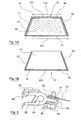
- the blind is intended to equip a rear window of trapezoidal shape, the lower side 111 being wider than the width of the upper side 112.
- the canvas 12 must of course have a similar shape. This assumes that the print is of a length corresponding to that of the short side of the trapezoid defined by the canvas, while the slot 14 allowing the passage of the canvas under the shelf rear must have a length corresponding to the width of the long side of this trapeze.
- the draw bar 13 is integral with runners running in rails 17, 18 mounted on the structure and / or the trim of the vehicle. These rails 17 and 18 follow also the trapezoidal shape of the glass, and are therefore not parallel. The variation in spacing between these rails is compensated, in a known manner, by the use of sliding end elements, to form a bar telescopic.
- the invention relates particularly to the mounting of the rails on the structure of the vehicle.
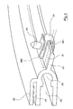
- the rail has a fixing portion, which extends substantially opposite the opening of the rail, and the shape of which is chosen to come into contact with a sheet metal element of the vehicle structure 31 ( Figure 3), to which it will be secured.
- this fixing portion are of course adapted depending on the needs, the shape and location of the sheet, and the various constraints imposed by the vehicle.
- the rail is here a monobloc element obtained for example by extrusion or by molding.
- the fixing portion 21 is then pierced with several openings which will allow the passage of the screws 23.
- a staple 24 is attached to the portion of attachment 21, at each of the openings which have been drilled.
- This staple 24 has a general S shape, defining two jumpers opening in opposite directions. The first jumper 241 overlaps the portion of attachment 21, while the second rider 242 straddles the structural sheet of the vehicle.
- the rail is thus supplied to the manufacturer pre-equipped with staples. It is so easy for the fitter to install the rail on the sheet metal element 31 provided for this effect.
- the jumper 242 then temporarily secures the rail to the sheet metal, and the fitter does not need to hold the rail, or immobilize it with others elements.
- the clips allow easy adjustment, on the one hand while playing the guide role of the assembly, since they indicate the location of the openings made in the fixing portion 21, and on the other hand because they allow the rail to be moved relative to the sheet until it is in the good position.
- the fitter then only has to bring back the final fixing means, which here are pins, or screws, 23.
- This screw is mounted through clip 24, of course provided with the openings necessary for the passage of the screw.
- the clip also holds the screw temporarily, before screwing.
- the jumper 241 can comprise means 32 for receiving and holding the head 33 of the screw.
- the rail of Figure 2 is a curved rail. he can of course, also be straight, and more generally of any suitable shape constraints imposed by the vehicle. In addition, the rails can of course be parallel to each other or not.
- This rail comprises a first housing 25 of essentially section rectangular, in which the shoe circulates, and a portion 26 of section essentially circular intended to receive the cable for actuating the pad.
- a slot 27 has been defined above the first housing 25. It is intended to receive a seal, which will be maintained by the teeth 28, and which will perform a function of hubcaps concealing the rail, so that it is invisible, or at least as little visible as possible inside the vehicle.
Landscapes
- Engineering & Computer Science (AREA)
- Mechanical Engineering (AREA)
- Curtains And Furnishings For Windows Or Doors (AREA)
- Operating, Guiding And Securing Of Roll- Type Closing Members (AREA)
- Body Structure For Vehicles (AREA)
Applications Claiming Priority (2)
| Application Number | Priority Date | Filing Date | Title |
|---|---|---|---|
| FR0301845A FR2851202B1 (fr) | 2003-02-13 | 2003-02-13 | Rail de guidage pre-equipe pour store de vehicule automobile, ensemble de store, procede d'assemblage et de montage et vehicules automobile correspondants |
| FR0301845 | 2003-02-13 |
Publications (2)
| Publication Number | Publication Date |
|---|---|
| EP1447252A2 true EP1447252A2 (de) | 2004-08-18 |
| EP1447252A3 EP1447252A3 (de) | 2006-10-25 |
Family
ID=32669377
Family Applications (1)
| Application Number | Title | Priority Date | Filing Date |
|---|---|---|---|
| EP04364010A Withdrawn EP1447252A3 (de) | 2003-02-13 | 2004-02-10 | Vormontierte Führungsschiene für Fahrzeugrollos, Rollo, Montageverfahren und entsprechendes Fahrzeug |
Country Status (2)
| Country | Link |
|---|---|
| EP (1) | EP1447252A3 (de) |
| FR (1) | FR2851202B1 (de) |
Cited By (1)
| Publication number | Priority date | Publication date | Assignee | Title |
|---|---|---|---|---|
| DE102008025741A1 (de) * | 2008-05-29 | 2009-12-03 | GM Global Technology Operations, Inc., Detroit | Sonnenbeschattungseinrichtung für Seiten- oder Heckfenster |
Family Cites Families (3)
| Publication number | Priority date | Publication date | Assignee | Title |
|---|---|---|---|---|
| FR2597919B1 (fr) * | 1986-04-29 | 1990-11-23 | Farnier & Penin | Store a enroulement et deroulement motorises |
| DE10005951A1 (de) * | 2000-02-09 | 2001-08-16 | Bos Gmbh | Heckfensterrollo |
| DE20210011U1 (de) * | 2002-06-28 | 2002-11-21 | Haas, Norbert, Dipl.-Ing., 80687 München | Blend-, Sonnen- und Sichtschutz für Fahrzeuge und stationären Einsatz |
-
2003
- 2003-02-13 FR FR0301845A patent/FR2851202B1/fr not_active Expired - Fee Related
-
2004
- 2004-02-10 EP EP04364010A patent/EP1447252A3/de not_active Withdrawn
Cited By (1)
| Publication number | Priority date | Publication date | Assignee | Title |
|---|---|---|---|---|
| DE102008025741A1 (de) * | 2008-05-29 | 2009-12-03 | GM Global Technology Operations, Inc., Detroit | Sonnenbeschattungseinrichtung für Seiten- oder Heckfenster |
Also Published As
| Publication number | Publication date |
|---|---|
| FR2851202A1 (fr) | 2004-08-20 |
| EP1447252A3 (de) | 2006-10-25 |
| FR2851202B1 (fr) | 2005-05-06 |
Similar Documents
| Publication | Publication Date | Title |
|---|---|---|
| FR3041905A1 (fr) | Dispositif vitre affleurant pour porte de vehicule, porte, vehicule automobile, procede de fabrication et dispositif d'etancheite correspondants. | |
| EP3647093B1 (de) | Verglaste vorrichtung eines fahrzeugs mit demontierbarem gleitschuh, entsprechende tür, entsprechendes fahrzeug und montageverfahren | |
| FR3021254A1 (fr) | Dispositif vitre affleurant pour porte de vehicule a panneau mobile reglable, porte et vehicule automobile correspondants. | |
| EP1447252A2 (de) | Vormontierte Führungsschiene für Fahrzeugrollos, Rollo, Montageverfahren und entsprechendes Fahrzeug | |
| EP1302347B1 (de) | Motorfahrzeugtür mit integrierter Rolloeinrichtung, Rollo, Zierabdeckung und korrespondierendes Fahrzeug | |
| EP1782985B1 (de) | Abdeckungsmodul für das Glasdach eines Fahrzeuges, und entsprechendes Fahrzeug | |
| FR2934202A1 (fr) | Store a enrouleur pour vehicule automobile a moyens d'equilibrage de la barre de tirage, et vehicule automobile correspondant. | |
| EP2230115B1 (de) | Abdeckungsvorrichtung für ein Glasdach eines Kraftfahrzeugs und entsprechendes Kraftfahrzeug | |
| EP1787839B2 (de) | Fensterrollo für Motorfahrzeug mit Mitteln zur Kompensation von Spiel und korrespondierendes Fahrzeug | |
| FR2882090A1 (fr) | Dispositif d'occultation a rideau enrouleur manuel et multi position | |
| EP1074411B1 (de) | Rollo mit vorgespanntem Gehäuse und korrespondierendes Montageverfahren | |
| EP1449696A1 (de) | Applikationsdichtung für die Schiene eines Sonnenschutzrollos und Fahrzeug mit solchem Sonnenschutzrollo | |
| EP1470942B1 (de) | Anordnung für die Befestigung eines Trägers für einen Sonnenvorhang | |
| FR2863552A1 (fr) | Dispositif enjoliveur pour store de vehicule, agrafe et vehicule correspondants | |
| FR2809135A1 (fr) | Store a enrouleur a barre de tirage mobile axialement | |
| EP4574484A1 (de) | Tür mit verstecktem rahmen für ein kraftfahrzeug | |
| FR2853591A1 (fr) | Palette pare-soleil mobile le long du pavillon d'un vehicule, dispositif d'occultation d'un pavillon couple a une telle palette pare-soleil et vehicule correspondant | |
| EP1683666A2 (de) | Abschirmeinrichtung für ein Motorfahrzeug und korrespondierende Fahrzeuge | |
| FR2919526A1 (fr) | Dispositif d'occultation pour vehicule automobile et vehicule correspondant | |
| EP1449694A1 (de) | Kraftfahrzeugblende, mit einer nicht rechteckigen Blende und mit einem verschiebbaren Zierelement und dessen Kraftfahrzeug | |
| EP1864861A1 (de) | Gepäckabdecksystem mit regulierbaren Verbindungselementen, Verbindungselement, Montageverfahren und entsprechendes Fahrzeug | |
| EP1623862A1 (de) | Rollo mit Spielausgleich für ein Fahrzeug und Unterbringung einer Aufhängevorrichtung für korrespondierendes Fahrzeug. | |
| FR2934522A1 (fr) | Systeme de support d'un store enrouleur pour vehicule automobile, a elements intermediaires profiles, elements, procede de montage et vehicule correspondants. | |
| FR2751272A1 (fr) | Store d'occultation d'une baie de vehicule | |
| FR2863551A1 (fr) | Dispositif enjoliveur pour store de portieres de vehicule, agraphe et vehicile correspondants |
Legal Events
| Date | Code | Title | Description |
|---|---|---|---|
| PUAI | Public reference made under article 153(3) epc to a published international application that has entered the european phase |
Free format text: ORIGINAL CODE: 0009012 |
|
| AK | Designated contracting states |
Kind code of ref document: A2 Designated state(s): AT BE BG CH CY CZ DE DK EE ES FI FR GB GR HU IE IT LI LU MC NL PT RO SE SI SK TR |
|
| AX | Request for extension of the european patent |
Extension state: AL LT LV MK |
|
| 17P | Request for examination filed |
Effective date: 20040920 |
|
| PUAL | Search report despatched |
Free format text: ORIGINAL CODE: 0009013 |
|
| AK | Designated contracting states |
Kind code of ref document: A3 Designated state(s): AT BE BG CH CY CZ DE DK EE ES FI FR GB GR HU IE IT LI LU MC NL PT RO SE SI SK TR |
|
| AX | Request for extension of the european patent |
Extension state: AL LT LV MK |
|
| AKX | Designation fees paid |
Designated state(s): DE FR |
|
| 17Q | First examination report despatched |
Effective date: 20070906 |
|
| GRAP | Despatch of communication of intention to grant a patent |
Free format text: ORIGINAL CODE: EPIDOSNIGR1 |
|
| STAA | Information on the status of an ep patent application or granted ep patent |
Free format text: STATUS: THE APPLICATION IS DEEMED TO BE WITHDRAWN |
|
| 18D | Application deemed to be withdrawn |
Effective date: 20090901 |