EP1446865B1 - Full wave dc/dc converter - Google Patents
Full wave dc/dc converter Download PDFInfo
- Publication number
- EP1446865B1 EP1446865B1 EP02762483A EP02762483A EP1446865B1 EP 1446865 B1 EP1446865 B1 EP 1446865B1 EP 02762483 A EP02762483 A EP 02762483A EP 02762483 A EP02762483 A EP 02762483A EP 1446865 B1 EP1446865 B1 EP 1446865B1
- Authority
- EP
- European Patent Office
- Prior art keywords
- current
- bridge
- direct
- control unit
- semiconductor switches
- Prior art date
- Legal status (The legal status is an assumption and is not a legal conclusion. Google has not performed a legal analysis and makes no representation as to the accuracy of the status listed.)
- Expired - Lifetime
Links
Images
Classifications
-
- H—ELECTRICITY
- H02—GENERATION; CONVERSION OR DISTRIBUTION OF ELECTRIC POWER
- H02M—APPARATUS FOR CONVERSION BETWEEN AC AND AC, BETWEEN AC AND DC, OR BETWEEN DC AND DC, AND FOR USE WITH MAINS OR SIMILAR POWER SUPPLY SYSTEMS; CONVERSION OF DC OR AC INPUT POWER INTO SURGE OUTPUT POWER; CONTROL OR REGULATION THEREOF
- H02M3/00—Conversion of DC power input into DC power output
- H02M3/02—Conversion of DC power input into DC power output without intermediate conversion into AC
- H02M3/04—Conversion of DC power input into DC power output without intermediate conversion into AC by static converters
- H02M3/10—Conversion of DC power input into DC power output without intermediate conversion into AC by static converters using discharge tubes with control electrode or semiconductor devices with control electrode
- H02M3/145—Conversion of DC power input into DC power output without intermediate conversion into AC by static converters using discharge tubes with control electrode or semiconductor devices with control electrode using devices of a triode or transistor type requiring continuous application of a control signal
- H02M3/155—Conversion of DC power input into DC power output without intermediate conversion into AC by static converters using discharge tubes with control electrode or semiconductor devices with control electrode using devices of a triode or transistor type requiring continuous application of a control signal using semiconductor devices only
- H02M3/156—Conversion of DC power input into DC power output without intermediate conversion into AC by static converters using discharge tubes with control electrode or semiconductor devices with control electrode using devices of a triode or transistor type requiring continuous application of a control signal using semiconductor devices only with automatic control of output voltage or current, e.g. switching regulators
- H02M3/158—Conversion of DC power input into DC power output without intermediate conversion into AC by static converters using discharge tubes with control electrode or semiconductor devices with control electrode using devices of a triode or transistor type requiring continuous application of a control signal using semiconductor devices only with automatic control of output voltage or current, e.g. switching regulators including plural semiconductor devices as final control devices for a single load
-
- H—ELECTRICITY
- H02—GENERATION; CONVERSION OR DISTRIBUTION OF ELECTRIC POWER
- H02M—APPARATUS FOR CONVERSION BETWEEN AC AND AC, BETWEEN AC AND DC, OR BETWEEN DC AND DC, AND FOR USE WITH MAINS OR SIMILAR POWER SUPPLY SYSTEMS; CONVERSION OF DC OR AC INPUT POWER INTO SURGE OUTPUT POWER; CONTROL OR REGULATION THEREOF
- H02M3/00—Conversion of DC power input into DC power output
- H02M3/02—Conversion of DC power input into DC power output without intermediate conversion into AC
- H02M3/04—Conversion of DC power input into DC power output without intermediate conversion into AC by static converters
- H02M3/10—Conversion of DC power input into DC power output without intermediate conversion into AC by static converters using discharge tubes with control electrode or semiconductor devices with control electrode
- H02M3/145—Conversion of DC power input into DC power output without intermediate conversion into AC by static converters using discharge tubes with control electrode or semiconductor devices with control electrode using devices of a triode or transistor type requiring continuous application of a control signal
- H02M3/155—Conversion of DC power input into DC power output without intermediate conversion into AC by static converters using discharge tubes with control electrode or semiconductor devices with control electrode using devices of a triode or transistor type requiring continuous application of a control signal using semiconductor devices only
- H02M3/1555—Conversion of DC power input into DC power output without intermediate conversion into AC by static converters using discharge tubes with control electrode or semiconductor devices with control electrode using devices of a triode or transistor type requiring continuous application of a control signal using semiconductor devices only for the generation of a regulated current to a load whose impedance is substantially inductive
Definitions
- the present invention relates to a control unit for controlling a direct-current load, said control unit comprising a DC/DC bridge provided with controllable semiconductor switches, said bridge having two bridge sections, one of which bridge sections conducts direct current while the other one is controlled via PWM to regulate the current magnitude.
- Elevator motor drives may be either alternating-current or direct-current motor drives.
- the drives may be controlled e.g. via PWM (Pulse Width Modulation).
- PWM Pulse Width Modulation
- alternating-current motor drives are fairly common, especially because of the simple construction of alternating-current motors.
- direct-current motor drives are still in use. Neither is it always appropriate to replace a direct-current motor drive with an alternating-current motor drive, because e.g. gearless direct-current motor drives and the direct-current motors used in them are durable and it is therefore unnecessary to replace them with alternating-current motor drives. Besides, replacing the motor entails relatively high costs.
- the object of the invention is to eliminate the drawbacks of prior-art technology and achieve a new type of PWM-controlled control unit for controlling a direct-current load, such as a direct-current motor.
- the solution of the invention is based on a new principle of power electronics topology, wherein it is possible to utilize the technology of alternating-current drives in the control off direct-current motors.
- a PWM-controlled bridge section consists of two bridge arms, and the semiconductor switches of the bridge arms are turned alternately into the conducting state.
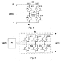
- Fig. 1 presents a prior-art PWM-controlled H-bridge H1 of a direct-current motor drive intended e.g. for an elevator application. It consists of two bridge arms H11 and H12 connected to a direct-current source UDC, each arm containing controllable semiconductor switches S11 - S14 for the positive and negative poles, consisting of e.g. an inverse parallel connection of an IGBT transistor and a diode.
- the bridge feeds a direct-current load L1, such as the direct-current motor of an elevator.
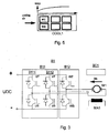
- Fig. 2 correspondingly presents a network bridge A1 as used in a prior-art three-phase alternating-current drive to rectify the alternating voltage of the network UAC into a direct voltage UDC, and an alternating-current inductor unit P1 connected before it.
- the bridge has in the upper and lower arms controllable semiconductor switches S21 - S26, which are connected to each network phase and which may also consist of e.g. an inverse parallel connection of an IGBT transistor and a diode.
- the electric motor drive of the invention is like a prior-art three-phase alternating-current drive comprising a network converter (rectifier bridge), a motor bridge and inductors.
- the present invention relates expressly to the DC/DC bridge feeding the motor.
- the network bridge and the inductors may be e.g. as presented in Fig. 2 .
- the same type of controllable semiconductor switches can be used in both the rectifier bridge and the motor bridge.
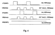
- Fig. 3 presents a DC/DC bridge B1 according to the invention, which is used to feed a direct-current motor M1, a direct current Idc flowing in the motor.
- the bridge is controlled by a control unit BC1.
- Magnetization of the motor is accomplished using a separate magnetizing unit MA1, which is controlled in a manner known in itself.
- the DC/DC bridge presented in Fig. 3 comprises two bridge sections B11, B12.
- the first bridge section in the bridge according to Fig. 3 comprises two arms B111 and B112, each containing controllable semiconductor switches UT, UB, VT, VB for the positive pole and the negative pole.
- the second bridge section B12 consists of a single arm with controllable semiconductor switches WT and WB for the positive and negative poles.
- the bridge as a whole has three arms, corresponding to a three-phase DC/AC bridge.
- the modulation of the DC/DC bridge of the invention is done as follows:
- the PWM-controlled direct-current drive of the invention can use the same kind of semiconductor switches for PWM control as are used in an alternating-current drive. Instead of alternating current, a zero-frequency is used (field not rotating).
- a high-frequency PWM control signal typically of a frequency of a few kHz; two of the switches, WT and WB, can be used so select the torque direction (up/down), and the switches in question conduct pure DC current.
- the switches UT, UB, VT, VB used for PWM control are turned on/off at a frequency of a few kHz to control the magnitude of the current Icd (the torque).
- Fig. 4 represents the conduction times of switches UT, VT and WT as well as the conduction times of switches UB and diodes VB.
- the invention provides the advantage that the power stage of an alternating-current drive can be fully utilized in a direct-current drive.
- Thermal dissipation in the IGBTs used in the circuit is typically double the dissipation in switches that are not used in PWM control. Therefore, according to the invention, switches UT, VT and WT are only kept conducting for at most 50% of the time in a cyclic manner. The conduction period varies according to the voltage (current) required.
- direct-current switches may have higher dissipation because direct-current losses are slightly greater than switching-PWM-losses. Therefore, switches WT and WB are placed on the air intake side of the cooling segment COOL1 ( Fig. 5 ) as it is cooler than the middle part of the segment or the air exit side, as indicated by the temperature curve TEMP.
- the switches used may also consist of other fully gate-controlled components.
- the load may also consist of e.g. a braking magnet of an elevator.
- the arrangement of the invention can be used in a wide range of electric drives.
- By applying the operating principle of the invention it will be possible to cover the power range of direct-current elevator drives using the latest IGBT technology.
- Alternating-current and direct-current drive modules can be assembled on the same production line, and the application can be selected mainly via software control.
Landscapes
- Engineering & Computer Science (AREA)
- Power Engineering (AREA)
- Control Of Direct Current Motors (AREA)
- Elevator Control (AREA)
- Control Of Ac Motors In General (AREA)
- Rectifiers (AREA)
Applications Claiming Priority (3)
| Application Number | Priority Date | Filing Date | Title |
|---|---|---|---|
| FI20012244A FI112297B (fi) | 2001-11-19 | 2001-11-19 | Ohjausyksikkö tasavirtakuorman ohjaamiseksi |
| FI20012244 | 2001-11-19 | ||
| PCT/FI2002/000767 WO2003044935A1 (en) | 2001-11-19 | 2002-09-24 | Full wave dc/dc converter |
Publications (2)
| Publication Number | Publication Date |
|---|---|
| EP1446865A1 EP1446865A1 (en) | 2004-08-18 |
| EP1446865B1 true EP1446865B1 (en) | 2010-03-31 |
Family
ID=8562284
Family Applications (1)
| Application Number | Title | Priority Date | Filing Date |
|---|---|---|---|
| EP02762483A Expired - Lifetime EP1446865B1 (en) | 2001-11-19 | 2002-09-24 | Full wave dc/dc converter |
Country Status (10)
Families Citing this family (4)
| Publication number | Priority date | Publication date | Assignee | Title |
|---|---|---|---|---|
| US6898094B2 (en) * | 2001-11-19 | 2005-05-24 | Kone Corporation | DC/DC bridge control unit for controlling a direct-current load |
| EP2303747B1 (en) * | 2008-06-17 | 2013-04-10 | Otis Elevator Company | Safe control of a brake using low power control devices |
| EP3214032B1 (en) * | 2016-03-03 | 2020-04-29 | Kone Corporation | Adjustable brake controller of an elevator brake, elevator brake and elevator |
| CN110880502B (zh) * | 2018-09-05 | 2022-10-14 | 无锡华润上华科技有限公司 | 半导体结构及电机驱动装置 |
Family Cites Families (9)
| Publication number | Priority date | Publication date | Assignee | Title |
|---|---|---|---|---|
| YU174183A (en) | 1983-08-23 | 1986-04-30 | Iskra Sozd Elektro Indus | Electronic circuit for organizinga the control of a transistor bridge |
| US5107190A (en) * | 1990-06-22 | 1992-04-21 | Motorola, Inc. | Means and method for optimizing the switching performance of power amplifiers |
| US5757636A (en) * | 1994-12-08 | 1998-05-26 | Pwm Drives Limited | Multi-phase inverters utilizing discontinuous PWM with dead bands |
| JPH08331882A (ja) * | 1995-03-24 | 1996-12-13 | Seiko Epson Corp | モータ制御装置 |
| JPH10164888A (ja) * | 1996-11-29 | 1998-06-19 | Hitachi Medical Corp | モータ駆動制御装置 |
| JPH10271889A (ja) | 1997-03-28 | 1998-10-09 | Komatsu Ltd | 電動式パワーステアリング制御装置 |
| US5912813A (en) * | 1997-10-01 | 1999-06-15 | Allen-Bradley Company, Llc | Method and apparatus for controlling reflected voltage using a motor controller |
| US6172882B1 (en) * | 1998-12-22 | 2001-01-09 | Tdk Corporation | Partial resonance PWM converter |
| JP3555567B2 (ja) * | 2000-09-04 | 2004-08-18 | 日産自動車株式会社 | 回転電機の制御装置 |
-
2001
- 2001-11-19 FI FI20012244A patent/FI112297B/fi not_active IP Right Cessation
-
2002
- 2002-09-24 EP EP02762483A patent/EP1446865B1/en not_active Expired - Lifetime
- 2002-09-24 DE DE60235827T patent/DE60235827D1/de not_active Expired - Lifetime
- 2002-09-24 AU AU2002327865A patent/AU2002327865B2/en not_active Ceased
- 2002-09-24 BR BRPI0214246A patent/BRPI0214246B1/pt not_active IP Right Cessation
- 2002-09-24 CN CNB028229746A patent/CN100338862C/zh not_active Expired - Fee Related
- 2002-09-24 WO PCT/FI2002/000767 patent/WO2003044935A1/en active IP Right Grant
- 2002-09-24 JP JP2003533381A patent/JP3764455B2/ja not_active Expired - Fee Related
- 2002-09-24 CA CA002463832A patent/CA2463832C/en not_active Expired - Fee Related
-
2003
- 2003-01-28 US US10/352,205 patent/US6697273B1/en not_active Expired - Lifetime
Also Published As
| Publication number | Publication date |
|---|---|
| EP1446865A1 (en) | 2004-08-18 |
| BRPI0214246B1 (pt) | 2016-02-10 |
| FI20012244A0 (fi) | 2001-11-19 |
| JP2004522400A (ja) | 2004-07-22 |
| DE60235827D1 (de) | 2010-05-12 |
| AU2002327865A1 (en) | 2003-06-10 |
| CA2463832C (en) | 2006-11-07 |
| CN100338862C (zh) | 2007-09-19 |
| FI20012244A7 (fi) | 2003-05-20 |
| CN1589518A (zh) | 2005-03-02 |
| WO2003044935A1 (en) | 2003-05-30 |
| HK1070475A1 (en) | 2005-06-17 |
| JP3764455B2 (ja) | 2006-04-05 |
| CA2463832A1 (en) | 2003-05-30 |
| BR0214246A (pt) | 2004-09-21 |
| US6697273B1 (en) | 2004-02-24 |
| FI112297B (fi) | 2003-11-14 |
| AU2002327865B2 (en) | 2006-04-06 |
Similar Documents
| Publication | Publication Date | Title |
|---|---|---|
| US8816625B2 (en) | Integrated regenerative AC drive with solid state precharging | |
| US7906922B2 (en) | Electric motor drive employing hybrid, hysteretic/pulse-width-modulated dynamic braking | |
| JP5860581B2 (ja) | 電力コンバータを提供するシステム及び方法 | |
| US7253574B2 (en) | Effective switching frequency multiplier inverter | |
| WO2020219857A1 (en) | Motor drive topologies for traction and charging in electrified vehicles | |
| US6898094B2 (en) | DC/DC bridge control unit for controlling a direct-current load | |
| EP2939339B1 (en) | Ac to ac converter and method of operation thereof for soft starting motors and other applications | |
| EP1446865B1 (en) | Full wave dc/dc converter | |
| CA2514863C (en) | Dc/dc bridge for controlling a direct-current load | |
| US20060208674A1 (en) | Controller, drive assembly and half-bridge assembly for providing a voltage | |
| AU2008297052B2 (en) | DC/DC bridge | |
| HK1070475B (en) | Full wave dc/dc converter | |
| FI113506B (fi) | DC/DC-silta tasavirtakuorman ohjaamiseksi | |
| HK1086115B (en) | Dc/dc bridge for controlling a direct-current load | |
| Sugden et al. | Low-power controlled-speed drives using SR motors | |
| JP2006211827A (ja) | 電力変換装置 | |
| KR20070047407A (ko) | 승압 인버터 |
Legal Events
| Date | Code | Title | Description |
|---|---|---|---|
| PUAI | Public reference made under article 153(3) epc to a published international application that has entered the european phase |
Free format text: ORIGINAL CODE: 0009012 |
|
| 17P | Request for examination filed |
Effective date: 20040326 |
|
| AK | Designated contracting states |
Kind code of ref document: A1 Designated state(s): AT BE BG CH CY CZ DE DK EE ES FI FR GB GR IE IT LI LU MC NL PT SE SK TR |
|
| AX | Request for extension of the european patent |
Extension state: AL LT LV MK RO SI |
|
| GRAP | Despatch of communication of intention to grant a patent |
Free format text: ORIGINAL CODE: EPIDOSNIGR1 |
|
| RBV | Designated contracting states (corrected) |
Designated state(s): CH DE FR GB LI |
|
| GRAS | Grant fee paid |
Free format text: ORIGINAL CODE: EPIDOSNIGR3 |
|
| GRAA | (expected) grant |
Free format text: ORIGINAL CODE: 0009210 |
|
| AK | Designated contracting states |
Kind code of ref document: B1 Designated state(s): CH DE FR GB LI |
|
| REG | Reference to a national code |
Ref country code: GB Ref legal event code: FG4D Ref country code: CH Ref legal event code: EP |
|
| REF | Corresponds to: |
Ref document number: 60235827 Country of ref document: DE Date of ref document: 20100512 Kind code of ref document: P |
|
| PLBE | No opposition filed within time limit |
Free format text: ORIGINAL CODE: 0009261 |
|
| 26N | No opposition filed |
Effective date: 20110104 |
|
| REG | Reference to a national code |
Ref country code: FR Ref legal event code: PLFP Year of fee payment: 15 |
|
| REG | Reference to a national code |
Ref country code: FR Ref legal event code: PLFP Year of fee payment: 16 |
|
| PGFP | Annual fee paid to national office [announced via postgrant information from national office to epo] |
Ref country code: CH Payment date: 20170921 Year of fee payment: 16 |
|
| REG | Reference to a national code |
Ref country code: FR Ref legal event code: PLFP Year of fee payment: 17 |
|
| PGFP | Annual fee paid to national office [announced via postgrant information from national office to epo] |
Ref country code: FR Payment date: 20180924 Year of fee payment: 17 Ref country code: DE Payment date: 20180920 Year of fee payment: 17 |
|
| PGFP | Annual fee paid to national office [announced via postgrant information from national office to epo] |
Ref country code: GB Payment date: 20180919 Year of fee payment: 17 |
|
| REG | Reference to a national code |
Ref country code: CH Ref legal event code: PL |
|
| PG25 | Lapsed in a contracting state [announced via postgrant information from national office to epo] |
Ref country code: LI Free format text: LAPSE BECAUSE OF NON-PAYMENT OF DUE FEES Effective date: 20180930 Ref country code: CH Free format text: LAPSE BECAUSE OF NON-PAYMENT OF DUE FEES Effective date: 20180930 |
|
| REG | Reference to a national code |
Ref country code: DE Ref legal event code: R119 Ref document number: 60235827 Country of ref document: DE |
|
| PG25 | Lapsed in a contracting state [announced via postgrant information from national office to epo] |
Ref country code: DE Free format text: LAPSE BECAUSE OF NON-PAYMENT OF DUE FEES Effective date: 20200401 |
|
| GBPC | Gb: european patent ceased through non-payment of renewal fee |
Effective date: 20190924 |
|
| PG25 | Lapsed in a contracting state [announced via postgrant information from national office to epo] |
Ref country code: GB Free format text: LAPSE BECAUSE OF NON-PAYMENT OF DUE FEES Effective date: 20190924 Ref country code: FR Free format text: LAPSE BECAUSE OF NON-PAYMENT OF DUE FEES Effective date: 20190930 |