EP1446546B1 - Dispositif charniere pour systeme de vitrage - Google Patents
Dispositif charniere pour systeme de vitrage Download PDFInfo
- Publication number
- EP1446546B1 EP1446546B1 EP20020774798 EP02774798A EP1446546B1 EP 1446546 B1 EP1446546 B1 EP 1446546B1 EP 20020774798 EP20020774798 EP 20020774798 EP 02774798 A EP02774798 A EP 02774798A EP 1446546 B1 EP1446546 B1 EP 1446546B1
- Authority
- EP
- European Patent Office
- Prior art keywords
- piece
- locking
- hinging
- frame part
- hinging piece
- Prior art date
- Legal status (The legal status is an assumption and is not a legal conclusion. Google has not performed a legal analysis and makes no representation as to the accuracy of the status listed.)
- Expired - Lifetime
Links
- 239000011521 glass Substances 0.000 claims abstract description 50
- 239000000463 material Substances 0.000 description 3
- 239000002184 metal Substances 0.000 description 2
- 238000005452 bending Methods 0.000 description 1
- 238000010276 construction Methods 0.000 description 1
- 238000000034 method Methods 0.000 description 1
- 238000009418 renovation Methods 0.000 description 1
- 238000005096 rolling process Methods 0.000 description 1
- 210000002105 tongue Anatomy 0.000 description 1
Images


Classifications
-
- E—FIXED CONSTRUCTIONS
- E06—DOORS, WINDOWS, SHUTTERS, OR ROLLER BLINDS IN GENERAL; LADDERS
- E06B—FIXED OR MOVABLE CLOSURES FOR OPENINGS IN BUILDINGS, VEHICLES, FENCES OR LIKE ENCLOSURES IN GENERAL, e.g. DOORS, WINDOWS, BLINDS, GATES
- E06B3/00—Window sashes, door leaves, or like elements for closing wall or like openings; Layout of fixed or moving closures, e.g. windows in wall or like openings; Features of rigidly-mounted outer frames relating to the mounting of wing frames
- E06B3/92—Doors or windows extensible when set in position
- E06B3/922—Doors or windows extensible when set in position with several wings opening horizontally towards the same side of the opening and each closing a separate part of the opening
- E06B3/924—Doors or windows extensible when set in position with several wings opening horizontally towards the same side of the opening and each closing a separate part of the opening positioned in one plane when closed
-
- E—FIXED CONSTRUCTIONS
- E05—LOCKS; KEYS; WINDOW OR DOOR FITTINGS; SAFES
- E05D—HINGES OR SUSPENSION DEVICES FOR DOORS, WINDOWS OR WINGS
- E05D15/00—Suspension arrangements for wings
- E05D15/06—Suspension arrangements for wings for wings sliding horizontally more or less in their own plane
- E05D15/0604—Suspension arrangements for wings for wings sliding horizontally more or less in their own plane allowing an additional movement
-
- E—FIXED CONSTRUCTIONS
- E05—LOCKS; KEYS; WINDOW OR DOOR FITTINGS; SAFES
- E05Y—INDEXING SCHEME ASSOCIATED WITH SUBCLASSES E05D AND E05F, RELATING TO CONSTRUCTION ELEMENTS, ELECTRIC CONTROL, POWER SUPPLY, POWER SIGNAL OR TRANSMISSION, USER INTERFACES, MOUNTING OR COUPLING, DETAILS, ACCESSORIES, AUXILIARY OPERATIONS NOT OTHERWISE PROVIDED FOR, APPLICATION THEREOF
- E05Y2201/00—Constructional elements; Accessories therefor
- E05Y2201/20—Brakes; Disengaging means; Holders; Stops; Valves; Accessories therefor
- E05Y2201/218—Holders
- E05Y2201/22—Locks
-
- E—FIXED CONSTRUCTIONS
- E05—LOCKS; KEYS; WINDOW OR DOOR FITTINGS; SAFES
- E05Y—INDEXING SCHEME ASSOCIATED WITH SUBCLASSES E05D AND E05F, RELATING TO CONSTRUCTION ELEMENTS, ELECTRIC CONTROL, POWER SUPPLY, POWER SIGNAL OR TRANSMISSION, USER INTERFACES, MOUNTING OR COUPLING, DETAILS, ACCESSORIES, AUXILIARY OPERATIONS NOT OTHERWISE PROVIDED FOR, APPLICATION THEREOF
- E05Y2201/00—Constructional elements; Accessories therefor
- E05Y2201/60—Suspension or transmission members; Accessories therefor
- E05Y2201/622—Suspension or transmission members elements
- E05Y2201/688—Rollers
- E05Y2201/692—Rollers having vertical axes
-
- E—FIXED CONSTRUCTIONS
- E05—LOCKS; KEYS; WINDOW OR DOOR FITTINGS; SAFES
- E05Y—INDEXING SCHEME ASSOCIATED WITH SUBCLASSES E05D AND E05F, RELATING TO CONSTRUCTION ELEMENTS, ELECTRIC CONTROL, POWER SUPPLY, POWER SIGNAL OR TRANSMISSION, USER INTERFACES, MOUNTING OR COUPLING, DETAILS, ACCESSORIES, AUXILIARY OPERATIONS NOT OTHERWISE PROVIDED FOR, APPLICATION THEREOF
- E05Y2900/00—Application of doors, windows, wings or fittings thereof
- E05Y2900/10—Application of doors, windows, wings or fittings thereof for buildings or parts thereof
- E05Y2900/13—Type of wing
- E05Y2900/148—Windows
- E05Y2900/15—Balcony glazing
Definitions
- the invention relates to a hinging device according to the preamble of claim 1.
- the invention also relates to a frame part of a hinging arrangement for a glazing system according to the preamble of claim 15.
- a hinging device and a frame part as in the preambles of Claims 1 and 15, respectively is known from WO 92/17673 .
- glazing systems of prior art are installed in connection with balconies, said glazing systems being called for example balcony glazings.
- the systems typically comprise an upper profile and a lower profile inside which necessary guide members are placed, single glass panes being suspended between said guide members.
- the profiles typically extend horizontally and they are fastened to the structures of the building.
- guide members it is possible to open and close individual glass panes, typically around a vertical axis of rotation, and they can also be transferred aside along the profiles, wherein several glass panes form a vertical stack, and the balcony is completely open.
- the guide members comprise a hinging and locking piece for each glass pane, by means of which the glass panes that have been turned aside are interlocked.
- the pieces are positioned against each other and locked when the glass panes are turned and taken close to each other.
- Said pieces are positioned at a distance from each other when the glass panes extend straight up, wherein the glass panes form a continuous wall, and the distance of the pieces corresponds to the width of the glass panes.
- Application publication EP 1 085 156 A1 discloses a known method for locking the hinging piece and the pivoted glass pane in their places, but there is, however, such a problem that the hinging piece must be fixed precisely at the location of the locking piece, said locking pieces being located only within a fixed minimum distance from each other.
- the hinging piece must be fixed precisely at the location of the locking piece, said locking pieces being located only within a fixed minimum distance from each other.
- the tongues that function as locking devices must be positioned accurately and in a stationary manner to a predetermined position.
- the glass pane does not have to be positioned in relation to the profile in connection with the locking, wherein it is sufficient that the glass panes, and at the same time the locking pieces are pressed against each other. Furthermore, the locking piece guides itself to the correct position inside the profile, wherein it is not necessary to fix the locking piece to a predetermined position, wherein it can rotate freely.
- the structure of the locking piece is, however, problematic in view of the torque forces, wherein bending forces are exerted thereon that are caused by the weight of the glass panes that hang on the support of a hinge pin. This restricts the selection of materials and the forces may force the locking piece for example due to deformation to a position in which the locking cannot be performed successfully or the locking piece is not capable of easily moving inside the profile.
- the hinging piece according to the invention is presented in claim 1.
- the frame part of a hinging arrangement for a glazing system is presented in claim 15.
- the locking piece can be suspended from the hinge pin in such a manner that it is capable of hanging freely.
- the hinge pin according to the invention carries the entire weight of the glass panes, and the weight is not transmitted to the locking piece, to the locking means or through them to the guide. In connection with the locking it is not necessary to apply any more force that is necessary to turn the glass pane, and the locking does not require accurate positioning with respect to the profile.
- the way in which the locking piece is attached enables the use of quite different locking pieces, and their easy replacement, and it is not even necessary to install the locking pieces to the hinging piece, if locking is not necessary.
- the locking piece does, however, contain the necessary locking means, wherein it is especially easy to add the locking at a later stage. When the locking is added, it is not necessary to change the profile or attach additional parts.
- the hinging piece according to the invention contains a set of wheels and locking means as well as fastening means for the glass panes arranged in the same piece that pivots around a rotating axis in the Y direction and supports the glass panes.
- the locking means are intended to function together with the locking piece that is fastened to the adjacent hinging piece.
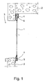
- a glazing system that has been installed in its place typically comprises several successive glass panes 1 that can be moved.
- the glass panes 1 have a rectangular form, and they are positioned in the X and Y direction, wherein they are in an upright position, forming a closed wall when placed one after the other. They can be transferred in the X direction that is typically the horizontal direction.
- the glass panes 1 can be opened into a position in which they extend in the Y and Z direction, said position being perpendicular to the closed position. In this position the glass panes 1 can be moved aside in such a manner that they are positioned side by side close to each other, wherein they are stored on one side of an opening 3 in a building 2.
- the upper profile 4 and the lower profile 5 are positioned in parallel to the X direction and each one of them comprises the necessary guide members 6 and 7 to which the glass panes 1 are fastened both from above and below.
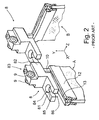
- Fig. 2 shows in more detail a locking piece 8 of related art that belongs to the necessary guide members and is placed especially in the upper profile 4.
- the piece 8 comprises rolls 9, on the support of which the glass panes 1 of Fig. 1 hang from the upper profile, and a hinge pin 10 that constitutes the necessary hinging piece and is fastened pivotably to the piece 8 and via which the glass pane is fastened to the piece 8.
- the locking piece 14 shown in Fig. 3 is constructed according to the aforementioned principle.
- the hinge pin 10 extends in parallel to the Y direction.
- the lateral direction, i.e. the Z direction is perpendicular both to the X direction and to the Y direction, wherein an orthogonal system of coordinates is formed at the same time.
- the piece 8 contains a rear end 82 that comprises fitting means 83 for fastening the hinge pin 10, the hinge pin 10 also pivoting in said fitting means, being at the same time arranged in said guide members.
- the piece 8 also contains a front end 81 comprising locking means 84 for locking the hinge pin 10 in a determined rotating position.
- the hinge pin 10 that can be locked is fastened to a preceding similar piece.
- the pieces 8 are typically identical, wherein the structure and the dimensions are similar.
- the pieces 8 are typically also symmetrical in relation to such a plane that coincides with the X and Y directions and is located on the central line of the piece.
- the front end 81 and the rear end 82 comprise an upper surface and a lower surface each, said surfaces being planar in the X and Z directions.
- the locking prevents the divergence of the pieces 8 in the X direction.
- the pieces 8 are transferred against each other, and the hinge pin 10 must be positioned in a locking gap 85.
- the width of the hinge pin 10 in the first rotating position A is smaller than in its predetermined second rotating position B. In the position A it has access to and away from the locking gap 85, but not in the position B.
- the aperture 86 of the locking gap 85 controls the access inside and outside.
- the glass panes typically also contain a fillet or a profile 12 to which the hinge pin 10 is fastened by means of a groove 13.
- Fig. 3 shows a locking piece 14 according to a preferred embodiment that is utilized in the invention.
- the piece 14 also contains a rear end 142 comprising fitting means 143 for fastening the hinge pin 10 (not shown in the drawing).
- the means 143 comprise at least an opening 146 that extends through the rear end 142 in the vertical direction and a recess 147 surrounding the opening 146, which recess is shown in the side projection of Fig. 4 (cross-section C - C) and in the position of Fig. 3 underneath the rear end 142.
- the hinge pin rotates in the opening 146 and the collar in the hinge pin is positioned in the recess 147, wherein the piece 14 can at the same time hang on the support of the hinge pin, wherein it is not necessary for the piece 14 to slide along the upper profile, wherein it does not support the glass panes on the upper profile. If necessary, it is possible to arrange a separate, preferably replaceable plate part of plastic material underneath the piece 14, which plate part slides well when needed.
- the structures inside the profile control the position of the piece 14 at least in the Z direction, if necessary.
- the piece 14 also contains a front end 141 comprising locking members 144 in whose locking gap 144a the hinge pin is positioned.
- the dimensioning of the aperture 144b of the locking gap 144a is adapted to allow the passage of the hinge pin in the position A of Fig. 2 , but not in the position B.
- the front end 141 is positioned underneath the rear end of the preceding piece and the rear end 142 is positioned underneath the front end of the next piece. Because of the step-shaped structure of the piece 14, the front and rear ends of the other pieces are positioned on different sides of the piece 14.
- the locking means 144 form a bifurcate fork 144c, 144d.
- the locking gap 144a is positioned between the branches 144c, 144d.
- Figure 5 shows a hinging piece 15 according to a preferred embodiment of the invention.
- the hinging piece 15 is placed together with the locking piece 14 inside a profile functioning as an upper profile.
- the hinging piece 15 can be connected especially to a locking piece 14 according to Fig. 3 , wherein they form the necessary guide members for the glazing system.
- the guide members are shown in Fig. 5 in a cross-section in the Y direction at the location of rotation axis 19, when positioned inside a profile 16 that is parallel to the X direction.
- the hinging piece 15 comprises two wheels 17 and 18 positioned in the horizontal plane on top of each other, said wheels forming a set of wheels on the same axis of rotation and symmetry 19 in the Y direction.
- the glass panes that are attached to a fillet 29 rest on the support of the wheels 17, 18, which, in turn, rest on the projections 20, 21 inside the upper profile 16 by means of their conical side surface.
- the projections 20 and 21 extend to opposite directions and they are positioned on different sides of the axis 19.
- Each wheel 17, 18 rests on the support of only one projection 20 or 21, along which the wheel rolls, wherein the wheels 17, 18 are capable of rotating around the rotation axis 19, wherein the glass panes and the guide members move by rolling along the profile 16 in the X direction.
- Each wheel 17, 18 comprises a hub part 24 or 25 that is typically made of metal, and a ring part 26 or 27 that is typically made of plastic material.
- the hub parts 24, 25 are locked in fixed manner, but the ring part 26, 27 is allowed to rotate centrally around the axis 19 and freely around the hub part 24, 25.
- intermediate rings 28 of metal must be placed between the hub parts 24, 25, wherein the height of the hub part 24, 25 is arranged to be greater than the height of the ring part 26, 27, so that the ring part would rotate freely.
- the hub part 24, 25 also contains at least one horizontal shoulder whose surface is directed downward, and a corresponding shoulder in the ring part 26, 27 is pressed against said horizontal shoulder.
- the hub parts 24 and 25, the ring parts 26 and 27, the screw 23 and the intermediate rings 28 are rotationally symmetrical in relation to the axis 19.
- a corresponding hinging piece 15 is placed inside the lower profile, but it is positioned upside down, and for example wheels 17 and 18 are not typically fastened thereto, wherein it does not contain a bearing part 31 and the narrowing of the frame part 22 extends all the way to the end.
- the screw 23 and the recess 30 are missing, wherein the purpose of the frame part 22 is to connect the glass panes to the lower profile and to prevent the movement in the Z direction.
- the parts 34, 35 are also higher, because the distance between the window pane and the lower profile is typically greater than in the upper profile.
- the frame part is preferably placed symmetrically and centrally on the axis 19.
- the frame part is also shown in Fig. 8 .
- the bearing means on top of the frame part 22 comprise a bearing part 31 that extends on a higher level than the locking piece 14, wherein the height of the piece 14 in the Y direction is smaller by the recess 147 than the height of the narrow collar i.e. the section 311 of the bearing part 31.
- the piece 14 is capable of rotating freely, if necessary, even if there was an intermediate ring 32 between the hub part 25 and the frame part 22.
- the hub part 25 can also be pressed directly against the frame part 22, wherein they are interlocked by means of a screw 23.
- the piece 14 must, however, be capable of pivoting freely, if necessary.
- the bearing part 31 also comprises a wide collar, i.e. a section 312 that is placed in the recess 147 of the piece 14, wherein the piece 14 rests on the support of the upper surface of the section 312, wherein the section 312 is preferably horizontal and its upper surface is directed upward.
- the height of the section 312 is smaller or equally great than the height of the recess 147, wherein the second locking piece moving underneath the rear end 142 of the piece 14 does not cling to the section 312.
- the frame part 22 extends downward in the Y direction and its diameter is preferably equal to the diameter of the section 312.
- the locking means formed in the frame part 22 comprise a locking part 33 that is intended to function together with the locking gap 144 of the locking piece 14 in the manner disclosed hereinabove and in connection with Fig. 2 as well.
- the horizontal cross-section of the locking part 33 follows the shape of a rectangular in such a manner that the distance between the short sides is greater than the distance between the long sides.
- the sides are preferably located symmetrically in relation to the axis 19, and the long sides are parallel to each other and extend vertically in the Y direction.
- the ring part 35 is capable of rotating freely around the rotation axis 19 and the bearing part 34, and it rests on the inner edges of the gap of the profile 16.
- the gap extending in the X direction is located on the lower surface of the profile 16.
- the diameter of the ring part 35 corresponds to the width of the gap, and thus it is possible to utilize the same to remove the clearance in the Z direction and to position the hinge pin 15 to the desired point, typically in the middle of the gap.
- the diameter of the ring part 35 can also be slightly larger than the width of the gap, wherein symmetrical narrowings must be made on the opposite sides of the ring part 35, the distance between the narrowings complying with the width of the gap.
- the diameter of the bearing part 34 is preferably slightly smaller than the greatest diameter of the locking part 33, wherein the ring part 35 rests against the shoulder between the locking part 33 and the bearing part 34.
- the ring part 35 also rests against the shoulder of the foot part 36, thus remaining by the gap in the profile 16.
- the bearing part 34 and the ring part 35 form the necessary sliding means by means of which the hinging part slides along the profile 19.
- the clearance between the ring part 35 and the bearing part 34 is arranged in such a manner that when the ring part 35 is pressed at the location of the narrowing in the bearing part 34, the ring part 35 yields, and it can be lifted up past the shoulder.
- the narrowings are arranged on opposite sides of the bearing part 34 and symmetrically in relation to the rotation axis 19. The narrowings are parallel to the narrowings in the locking part 33.
- the diameter of the section 312 must also be smaller than the inner diameter of the ring part 35.
- the widest part of the frame part 22 is located by the section 312.
- the hinge pin 15 is fastened to the fillet 29 by means of the foot part 36 that is presented in more detail also in Fig. 7 , wherein the glass panes are mounted underneath the piece 15 in the Y direction.
- the fillet 29 contains a gap extending in the X direction, said gap being narrower than the space inside the fillet 29 in which the foot part 36 is positioned.
- In the upper part of the foot part 36 there is a symmetrical narrowing 361 whose horizontal cross-section follows the shape of a rectangular in such a manner that the distance between the long sides equals the width of the gap.
- the long sides and their surfaces are parallel to the other narrowing surfaces of the frame part 22.
- the foot part 36 there is a symmetrical widening 362 whose width is greater than the width of the gap in the fillet 29 and it complies with the width of the free inner space of the fillet 29, wherein the foot part 36 and its widening 362 support the fillet 29.
- the widening 362 has preferably a substantially rectangular cross-section, but it can also be partly circular.
- On at least one side of the widening 362 there is an extension that extends in the X direction and whose width is greater than the width of the gap in the fillet 29.
- the width of the extension 363 preferably complies with the width of the widening 362 and on top of the extension there is a gap 37 that is open at least upward, preferably also to the sides in the Z direction.
- the recess 37 In the X direction of the fillet 29 the recess 37 is lined on one hand by the widening 362 and on the other hand by the end of the extension 363. It is possible to place a nut 38 in the recess 37, the outer appearance of said nut being such that its rotation in the recess 37 around the Y direction is prevented.
- the nut 38 is wider than the gap in the fillet 29, wherein it is possible to utilize said nut to fasten the foot part 36 and the fillet 29 together in a stationary manner, if a threaded screw 39 (shown by broken lines) is placed and tightened in the nut from above.
- the threaded screw 39 on one hand lifts up the nut 38 against the inner upper surface of the fillet 29, and on the other hand presses the foot part 36 against the inner lower surface of the fillet 29, wherein the hinge pin 15 and its frame part 22 are locked in their place in the X direction.
- the foot part 36, the nut 38 and the threaded screw 39 constitute the means intended for fastening of the glass panes, when the glass panes also comprise a fillet 29.
Landscapes
- Engineering & Computer Science (AREA)
- Mechanical Engineering (AREA)
- Civil Engineering (AREA)
- Structural Engineering (AREA)
- Securing Of Glass Panes Or The Like (AREA)
- Hinges (AREA)
- Closing And Opening Devices For Wings, And Checks For Wings (AREA)
- Glass Compositions (AREA)
- Re-Forming, After-Treatment, Cutting And Transporting Of Glass Products (AREA)
- Superstructure Of Vehicle (AREA)
Claims (17)
- Pièce charnière (15) pour système de vitrage, qui, lorsqu'elle est posée dans sa place, est censée être déplaçable dans la direction X lorsqu'elle est disposée dans un profilé de guidage (16) du système de vitrage, à laquelle les vitres (1) du système de vitrage sont censées être suspendues au moyen de ladite pièce charnière (15), ladite pièce comprenant :- un jeu de roues horizontal (17, 18) qui est disposé sur un axe de rotation (19) s'étendant dans la direction Y et censé supporter la pièce charnière (15) sur le profilé de guidage (16), et- une partie de châssis (22) qui est disposée afin de tourner autour dudit axe de rotation (19) avec les vitres,caractérisée en ce que la partie de châssis (22) comprend au moins :- des moyens de fixation (36) pour suspendre les vitres à la pièce charnière (15),- des moyen de verrouillage (33) qui sont disposés afin de verrouiller la pièce charnière (15) à une pièce de verrouillage lorsque la partie de châssis (22) se trouve dans une position de rotation prédéterminée, ladite pièce de verrouillage étant attachée à la pièce charnière adjacente lorsque deux pièces charnière (15) sont positionnées l'une à la suite de l'autre, dans laquelle le verrouillage empêche la divergence de pièces charnière (15) adjacentes l'une par rapport à l'autre dans la direction X, et- de moyens de support (31) qui sont disposés afin de fixer une pièce de verrouillage (14) sur la partie de châssis (22) de sorte que la partie de châssis (22) puisse pivoter autour dudit axe de rotation (19) relativement à la pièce de verrouillage (14).
- Pièce charnière selon la revendication 1, caractérisée en ce que la largeur hors-tout des moyens de verrouillage (33) dans la direction Z est plus petite dans la première position de rotation (A) que dans la seconde position de rotation (B) prédéterminée.
- Pièce charnière selon la revendication 1 ou 2, caractérisé en ce que les moyens de support (31) comprennent un premier collier (311) et un second collier (312) dont le diamètre est supérieur à celui du premier collier (311) et qui est positionné sous le premier collier (311), dans laquelle la pièce de verrouillage (14) est disposée afin de reposer sur le support du second collier (312) de sorte que sa rotation sur l'axe de rotation (19) soit permise.
- Pièce charnière selon l'une quelconque des revendications 1 à 3, caractérisée en ce que le jeu de roues (17, 18) censé assurer le déplacement de la pièce charnière (15) comprend au moins une roue (17, 18) qui est disposée afin de tourner autour de l'axe de rotation (19) s'étendant dans la direction Y, dans laquelle la partie de châssis (22) est suspendue sous le jeu de roues (17, 18).
- Pièce charnière selon la revendication 4, caractérisée en ce que la roue (17, 18) comprend une partie de moyeu (24, 25) via laquelle la roue est attachée à la partie de châssis (22) et une partie annulaire (26, 27) disposée afin de pivoter autour de la partie de moyeu (24, 25) et de l'axe de rotation (19).
- Pièce charnière selon l'une quelconque des revendications 1 à 5, caractérisée en ce qu'elle comprend également des moyens de coulissage (34, 35) qui sont disposés afin d'être positionnés contre le profilé de guidage, lorsque la pièce charnière (15) se déplace dans la direction X et de supporter la pièce charnière en place dans le direction Z, lesdits moyens de coulissage comprenant un anneau (35) qui est verrouillé autour de la partie de châssis (22), la rotation dudit anneau autour de l'axe de rotation (19) étant permise.
- Pièce charnière selon l'une quelconque des revendications 1 à 5, caractérisée en ce que les moyens de fixation (36) comprennent un élargissement (362) qui est disposé afin d'être positionné à l'intérieur d'un filet (29), auquel filet le verre est à son tour attaché, et un rétrécissement (361) qui est censé être positionné dans un vide du filet (29), et une extension (363) de l'élargissement (362) s'étendant dans la direction X de sorte que la combinaison d'un écrou et d'une vis peut être placée entre le filet (29) et l'extension (363) à l'intérieur du filet (29), ladite combinaison serrant et verrouillant l'extension (363) contre le filet (29).
- Pièce charnière selon l'une quelconque des revendications 1 à 7, caractérisée en ce que la pièce charnière (15) est disposée afin de pivoter vers une première position de rotation (A) qui correspond à la position de la vitre dans laquelle sa surface coïncide avec les directions X et Y, et au moins vers une seconde position de rotation (B) qui correspond à la position de la vitre dans laquelle sa surface coïncide avec les directions Y et Z, dans laquelle la direction X et la direction Z sont des directions essentiellement horizontales et la direction Y est une direction essentiellement verticale.
- Pièce charnière selon l'une quelconque des revendications 1 à 8, caractérisée en ce que la pièce charnière (14) comprend :- une extrémité arrière (142) comprenant des moyens d'adaptation (143) pour fixer la pièce charnière (15), dans laquelle la pièce charnière (15) qui supporte la vitre et s'étendant essentiellement dans la direction Y est censée pivoter, et- une extrémité avant (141) comprenant des moyens de verrouillage (144) pour verrouiller la pièce charnière (14) à la pièce charnière adjacente dans une position de rotation prédéterminée de la partie de châssis (22), lorsque deux pièces charnières (15) sont successivement positionnées dans la direction X, dans laquelle le verrouillage empêche la divergence de pièces charnière adjacentes (15) l'une par rapport à l'autre.
- Pièce charnière selon la revendication 9, caractérisée en ce que l'extrémité avant (141) est disposée afin d'être positionnée sous l'extrémité arrière de la pièce de verrouillage adjacente dans la direction Y, et en ce que l'extrémité arrière (142) est disposée afin d'être positionnée sous l'extrémité avant de la seconde pièce de verrouillage adjacente dans la direction Y, dans laquelle l'extrémité avant (141) est également disposée afin d'être positionnée sur un autre côté de la pièce que l'extrémité arrière (142).
- Pièce charnière selon la revendication 9 ou 10, caractérisée en ce que les moyens de verrouillage (144) de la pièce de verrouillage (14) comprennent un vide de verrouillage (144a) s'étendant au travers de l'extrémité avant (141) dans la direction Y et s'ouvrant en direction de la pièce de verrouillage adjacente dans la direction X, ledit vide de verrouillage étant disposé afin de recevoir la pièce charnière de la pièce de verrouillage précédente, dans laquelle l'ouverture (144b) du vide de verrouillage (144a) est disposé afin de permettre l'accès dudit axe de charnière à l'intérieur lorsqu'il se trouve dans une position de rotation (A) prédéterminée et d'empêcher l'accès dudit axe de charnière à l'extérieur lorsqu'il se trouve dans une seconde position (B) prédéterminée.
- Pièce de verrouillage selon la revendication 11, caractérisée en ce que les moyens de verrouillage (144) comprennent une fourche de bifurcation disposée afin de guider la pièce de charnière vers le vide de verrouillage (144a) positionné entre les branches.
- Pièce de charnière selon l'une quelconque des revendications 9 à 12, caractérisée en ce que la largeur hors-tout des moyens de verrouillage de la pièce de charnière (15) dans la direction Z dans la première position de rotation (A) est inférieure à celle dans la seconde position de rotation prédéterminée (B), et en ce que la largeur hors-tout de l'ouverture du vide de verrouillage dans la direction Z est inférieure à la largeur hors-tout des moyens de verrouillage dans la seconde position de rotation (B) et supérieure à la largeur hors-tout des moyens de verrouillage dans la première position de rotation (A).
- Pièce de charnière selon l'une quelconque des revendications 9 à 13, caractérisée en ce que les moyens d'adaptation de la pièce de charnière (14) comprennent au moins une ouverture (146) s'étendant dans la direction Y et au travers de l'extrémité arrière, ainsi qu'un retrait (147) entourant l'ouverture qui est situé entre l'extrémité arrière (142) et l'extrémité avant de la pièce suivante.
- Partie de châssis (22) pour pièce de charnière d'un système de vitrage, qui, lorsqu'elle est posée dans sa place, est censée être déplaçable dans la direction X lorsqu'elle est disposée dans un profilé de guidage (16) du système de vitrage, dans laquelle les vitres (1) du système de vitrage sont censées être suspendues ou reliées au moyen de ladite partie de châssis (22) de la pièce de charnière (15) qui est disposée afin de tourner avec les vitres autour d'un axe de rotation (A) s'étendant dans la direction Y,
caractérisée en ce que la partie de châssis (22) comprend au moins:- des moyens de fixation (36) pour suspendre les vitres à la pièce charnière (22),- des moyens de verrouillage (33) qui sont disposés afin de verrouiller la pièce charnière (22) à une pièce de verrouillage lorsque la partie de châssis (22) se trouve dans une position de rotation prédéterminée, ladite pièce de verrouillage étant attachée à la partie de châssis adjacente du dispositif charnière lorsque deux pièces de châssis (22) sont positionnées l'une à la suite de l'autre, dans laquelle le verrouillage empêche la divergence de pièces charnière (22) adjacentes l'une par rapport à l'autre dans la direction X. - Partie de châssis (22) selon la revendication 15, caractérisée en ce qu'elle comprend également des moyens de coulissage (34, 35) qui sont disposés afin d'être positionnés contre le profilé de guidage, lorsque la partie de châssis (22) se déplace dans la direction X et de supporter la pièce charnière en place dans la direction Z, lesdits moyens de coulissage comprenant un anneau (35) qui est verrouillé autour de la partie de châssis (22), la rotation dudit anneau autour de l'axe de rotation (19) étant permise.
- Partie de châssis (22) selon la revendication 15 ou 16, caractérisée en ce qu'elle comprend également des moyens de support (31) qui sont disposés afin de fixer une pièce de verrouillage (14) sur la partie de châssis (22) de sorte que la partie de châssis (22) puisse pivoter autour dudit axe de rotation (19) relativement à la pièce de verrouillage (14).
Applications Claiming Priority (3)
| Application Number | Priority Date | Filing Date | Title |
|---|---|---|---|
| FI20012130 | 2001-11-05 | ||
| FI20012130A FI116694B (fi) | 2001-11-05 | 2001-11-05 | Lasitusjärjestelmän saranointikappale |
| PCT/FI2002/000858 WO2003042482A1 (fr) | 2001-11-05 | 2002-11-05 | Dispositif charniere pour systeme de vitrage |
Publications (2)
| Publication Number | Publication Date |
|---|---|
| EP1446546A1 EP1446546A1 (fr) | 2004-08-18 |
| EP1446546B1 true EP1446546B1 (fr) | 2009-12-09 |
Family
ID=8562180
Family Applications (1)
| Application Number | Title | Priority Date | Filing Date |
|---|---|---|---|
| EP20020774798 Expired - Lifetime EP1446546B1 (fr) | 2001-11-05 | 2002-11-05 | Dispositif charniere pour systeme de vitrage |
Country Status (10)
| Country | Link |
|---|---|
| EP (1) | EP1446546B1 (fr) |
| CN (1) | CN100338328C (fr) |
| AT (1) | ATE451530T1 (fr) |
| DE (1) | DE60234709D1 (fr) |
| DK (1) | DK1446546T3 (fr) |
| ES (1) | ES2337988T3 (fr) |
| FI (1) | FI116694B (fr) |
| NO (1) | NO326740B1 (fr) |
| PT (1) | PT1446546E (fr) |
| WO (1) | WO2003042482A1 (fr) |
Families Citing this family (7)
| Publication number | Priority date | Publication date | Assignee | Title |
|---|---|---|---|---|
| AT7572U3 (de) * | 2004-12-09 | 2006-08-15 | Franz Haiderer | Schiebewandsystem |
| AT501398B1 (de) * | 2004-12-09 | 2008-01-15 | Franz Haiderer | Schiebewandsystem |
| FI119254B (fi) | 2006-08-16 | 2008-09-15 | Lumon Oy | Paneelijärjestelmä ja sen lukituksen ohjaus |
| FI119001B (fi) | 2006-08-16 | 2008-06-13 | Lumon Oy | Paneelijärjestelmä ja sen yläohjain |
| FI125865B (fi) | 2008-05-15 | 2016-03-15 | Lumon Oy | Paneeliin lukittava lista ja lasipaneeli |
| FI125283B (fi) | 2012-11-01 | 2015-08-14 | Lumon Invest Oy | Paneelijärjestelmä |
| ES1156759Y (es) * | 2016-03-14 | 2016-08-09 | Gonzalez Francisco Javier Ona | Dispositivo de cerrado para puerta que desliza y pivota |
Family Cites Families (6)
| Publication number | Priority date | Publication date | Assignee | Title |
|---|---|---|---|---|
| CN2076596U (zh) * | 1990-08-23 | 1991-05-08 | 刘新伯 | 滑移式开窗机构 |
| FI89532C (fi) * | 1991-10-14 | 1993-10-11 | Jarmo Sjoeholm | Gaongjaernsanordning |
| FI97990C (fi) * | 1995-04-21 | 1997-03-25 | Lasimyynti Juvonen Oy | Saranajärjestely parvekelasitusrakennetta tai vastaavaa varten |
| FI97636C (fi) * | 1995-04-21 | 1997-01-27 | Vantaan Asennuspalvelu Oy | Lukituslaitteisto |
| FI101823B (fi) * | 1997-04-15 | 1998-08-31 | Iloxi Oy | Lukituslaite |
| SE513747C2 (sv) * | 1998-03-04 | 2000-10-30 | Benth Loennberg | Anordning för vridbar och skjutbar upphängning av skivor |
-
2001
- 2001-11-05 FI FI20012130A patent/FI116694B/fi not_active IP Right Cessation
-
2002
- 2002-11-05 PT PT02774798T patent/PT1446546E/pt unknown
- 2002-11-05 DE DE60234709T patent/DE60234709D1/de not_active Expired - Lifetime
- 2002-11-05 WO PCT/FI2002/000858 patent/WO2003042482A1/fr not_active Application Discontinuation
- 2002-11-05 CN CNB028220943A patent/CN100338328C/zh not_active Expired - Fee Related
- 2002-11-05 AT AT02774798T patent/ATE451530T1/de active
- 2002-11-05 DK DK02774798T patent/DK1446546T3/da active
- 2002-11-05 ES ES02774798T patent/ES2337988T3/es not_active Expired - Lifetime
- 2002-11-05 EP EP20020774798 patent/EP1446546B1/fr not_active Expired - Lifetime
-
2004
- 2004-05-04 NO NO20041843A patent/NO326740B1/no not_active IP Right Cessation
Also Published As
| Publication number | Publication date |
|---|---|
| FI20012130A0 (fi) | 2001-11-05 |
| NO326740B1 (no) | 2009-02-09 |
| CN100338328C (zh) | 2007-09-19 |
| PT1446546E (pt) | 2010-03-01 |
| EP1446546A1 (fr) | 2004-08-18 |
| CN1582361A (zh) | 2005-02-16 |
| WO2003042482A1 (fr) | 2003-05-22 |
| DE60234709D1 (fr) | 2010-01-21 |
| DK1446546T3 (da) | 2010-04-12 |
| FI116694B (fi) | 2006-01-31 |
| ES2337988T3 (es) | 2010-05-03 |
| FI20012130A (fi) | 2003-05-06 |
| NO20041843L (no) | 2004-05-04 |
| ATE451530T1 (de) | 2009-12-15 |
Similar Documents
| Publication | Publication Date | Title |
|---|---|---|
| EP1446546B1 (fr) | Dispositif charniere pour systeme de vitrage | |
| EP1679281B1 (fr) | Dispositif d'ajustement pour guides | |
| NZ584905A (en) | Wheeled carriage for suspending a wing with an adjusting wedge for changing the height of the suspended wing | |
| AU2007221862A1 (en) | Device for holding panels and separation element | |
| CA2052996A1 (fr) | Console reglable pour batiments | |
| WO1994027015A1 (fr) | Porte coulissante ou systeme a baies coulissantes | |
| CN101316783A (zh) | 电梯的门装置 | |
| US20160201373A1 (en) | Running track device for the displaceable support of at least one first roller carriage and at least one second roller carriage | |
| EP1442192B1 (fr) | Piece de charniere et de verrouillage pour systeme de vitrage | |
| EP2886763A1 (fr) | Élément en verre | |
| EP1889996B1 (fr) | Système de panneaux et élément de guidage supérieur pour celui-ci | |
| KR100596183B1 (ko) | 건축용 안전 문 개폐장치 | |
| FI105711B (fi) | Sarana | |
| EP1947277A2 (fr) | Structure de vitrage de balcon | |
| CN216446736U (zh) | 一种缓解售货柜柜门下降的缓冲机构 | |
| CN214275253U (zh) | 一种线面式定位壁挂装置 | |
| JPH10121750A (ja) | 荷重解放用金具 | |
| CA2923572A1 (fr) | Mecanisme de porte coulissante pour portes vitrees | |
| FI91184C (fi) | Liukuikkunarakenne | |
| JPH0527656Y2 (fr) | ||
| AU743128B2 (en) | Overhead door track structure | |
| EP2518248A1 (fr) | Agencement de vitrage |
Legal Events
| Date | Code | Title | Description |
|---|---|---|---|
| PUAI | Public reference made under article 153(3) epc to a published international application that has entered the european phase |
Free format text: ORIGINAL CODE: 0009012 |
|
| 17P | Request for examination filed |
Effective date: 20040507 |
|
| AK | Designated contracting states |
Kind code of ref document: A1 Designated state(s): AT BE BG CH CY CZ DE DK EE ES FI FR GB GR IE IT LI LU MC NL PT SE SK TR |
|
| AX | Request for extension of the european patent |
Extension state: AL LT LV MK RO SI |
|
| GRAP | Despatch of communication of intention to grant a patent |
Free format text: ORIGINAL CODE: EPIDOSNIGR1 |
|
| GRAS | Grant fee paid |
Free format text: ORIGINAL CODE: EPIDOSNIGR3 |
|
| GRAA | (expected) grant |
Free format text: ORIGINAL CODE: 0009210 |
|
| RAP1 | Party data changed (applicant data changed or rights of an application transferred) |
Owner name: LUMON INVEST OY |
|
| AK | Designated contracting states |
Kind code of ref document: B1 Designated state(s): AT BE BG CH CY CZ DE DK EE ES FI FR GB GR IE IT LI LU MC NL PT SE SK TR |
|
| REG | Reference to a national code |
Ref country code: GB Ref legal event code: FG4D |
|
| REG | Reference to a national code |
Ref country code: CH Ref legal event code: EP |
|
| REG | Reference to a national code |
Ref country code: IE Ref legal event code: FG4D |
|
| REF | Corresponds to: |
Ref document number: 60234709 Country of ref document: DE Date of ref document: 20100121 Kind code of ref document: P |
|
| REG | Reference to a national code |
Ref country code: PT Ref legal event code: SC4A Free format text: AVAILABILITY OF NATIONAL TRANSLATION Effective date: 20100219 |
|
| REG | Reference to a national code |
Ref country code: CH Ref legal event code: NV Representative=s name: OFFICE ERNEST T. FREYLINGER S.A. C/O SCHLUEP & DEG |
|
| REG | Reference to a national code |
Ref country code: GR Ref legal event code: EP Ref document number: 20100400429 Country of ref document: GR |
|
| REG | Reference to a national code |
Ref country code: SE Ref legal event code: TRGR |
|
| REG | Reference to a national code |
Ref country code: NL Ref legal event code: T3 |
|
| REG | Reference to a national code |
Ref country code: DK Ref legal event code: T3 |
|
| REG | Reference to a national code |
Ref country code: ES Ref legal event code: FG2A Ref document number: 2337988 Country of ref document: ES Kind code of ref document: T3 |
|
| PG25 | Lapsed in a contracting state [announced via postgrant information from national office to epo] |
Ref country code: BG Free format text: LAPSE BECAUSE OF FAILURE TO SUBMIT A TRANSLATION OF THE DESCRIPTION OR TO PAY THE FEE WITHIN THE PRESCRIBED TIME-LIMIT Effective date: 20100309 |
|
| PG25 | Lapsed in a contracting state [announced via postgrant information from national office to epo] |
Ref country code: CZ Free format text: LAPSE BECAUSE OF FAILURE TO SUBMIT A TRANSLATION OF THE DESCRIPTION OR TO PAY THE FEE WITHIN THE PRESCRIBED TIME-LIMIT Effective date: 20091209 Ref country code: SK Free format text: LAPSE BECAUSE OF FAILURE TO SUBMIT A TRANSLATION OF THE DESCRIPTION OR TO PAY THE FEE WITHIN THE PRESCRIBED TIME-LIMIT Effective date: 20091209 |
|
| PLBE | No opposition filed within time limit |
Free format text: ORIGINAL CODE: 0009261 |
|
| STAA | Information on the status of an ep patent application or granted ep patent |
Free format text: STATUS: NO OPPOSITION FILED WITHIN TIME LIMIT |
|
| PG25 | Lapsed in a contracting state [announced via postgrant information from national office to epo] |
Ref country code: CY Free format text: LAPSE BECAUSE OF FAILURE TO SUBMIT A TRANSLATION OF THE DESCRIPTION OR TO PAY THE FEE WITHIN THE PRESCRIBED TIME-LIMIT Effective date: 20091209 |
|
| 26N | No opposition filed |
Effective date: 20100910 |
|
| PG25 | Lapsed in a contracting state [announced via postgrant information from national office to epo] |
Ref country code: MC Free format text: LAPSE BECAUSE OF NON-PAYMENT OF DUE FEES Effective date: 20101130 |
|
| PG25 | Lapsed in a contracting state [announced via postgrant information from national office to epo] |
Ref country code: TR Free format text: LAPSE BECAUSE OF FAILURE TO SUBMIT A TRANSLATION OF THE DESCRIPTION OR TO PAY THE FEE WITHIN THE PRESCRIBED TIME-LIMIT Effective date: 20091209 |
|
| PGFP | Annual fee paid to national office [announced via postgrant information from national office to epo] |
Ref country code: LU Payment date: 20141126 Year of fee payment: 13 |
|
| PGFP | Annual fee paid to national office [announced via postgrant information from national office to epo] |
Ref country code: GR Payment date: 20141121 Year of fee payment: 13 |
|
| PGFP | Annual fee paid to national office [announced via postgrant information from national office to epo] |
Ref country code: PT Payment date: 20141030 Year of fee payment: 13 |
|
| PGFP | Annual fee paid to national office [announced via postgrant information from national office to epo] |
Ref country code: IT Payment date: 20141125 Year of fee payment: 13 |
|
| PGFP | Annual fee paid to national office [announced via postgrant information from national office to epo] |
Ref country code: BE Payment date: 20141118 Year of fee payment: 13 |
|
| REG | Reference to a national code |
Ref country code: FR Ref legal event code: PLFP Year of fee payment: 14 |
|
| PGFP | Annual fee paid to national office [announced via postgrant information from national office to epo] |
Ref country code: IE Payment date: 20151123 Year of fee payment: 14 |
|
| REG | Reference to a national code |
Ref country code: PT Ref legal event code: MM4A Free format text: LAPSE DUE TO NON-PAYMENT OF FEES Effective date: 20160505 |
|
| PG25 | Lapsed in a contracting state [announced via postgrant information from national office to epo] |
Ref country code: LU Free format text: LAPSE BECAUSE OF NON-PAYMENT OF DUE FEES Effective date: 20151105 |
|
| PG25 | Lapsed in a contracting state [announced via postgrant information from national office to epo] |
Ref country code: GR Free format text: LAPSE BECAUSE OF NON-PAYMENT OF DUE FEES Effective date: 20160602 Ref country code: IT Free format text: LAPSE BECAUSE OF NON-PAYMENT OF DUE FEES Effective date: 20151105 |
|
| PG25 | Lapsed in a contracting state [announced via postgrant information from national office to epo] |
Ref country code: PT Free format text: LAPSE BECAUSE OF NON-PAYMENT OF DUE FEES Effective date: 20160505 |
|
| REG | Reference to a national code |
Ref country code: GR Ref legal event code: ML Ref document number: 20100400429 Country of ref document: GR Effective date: 20160602 |
|
| REG | Reference to a national code |
Ref country code: FR Ref legal event code: PLFP Year of fee payment: 15 |
|
| PGFP | Annual fee paid to national office [announced via postgrant information from national office to epo] |
Ref country code: NL Payment date: 20161117 Year of fee payment: 15 Ref country code: DK Payment date: 20161122 Year of fee payment: 15 Ref country code: EE Payment date: 20161129 Year of fee payment: 15 |
|
| PGFP | Annual fee paid to national office [announced via postgrant information from national office to epo] |
Ref country code: AT Payment date: 20161121 Year of fee payment: 15 |
|
| PG25 | Lapsed in a contracting state [announced via postgrant information from national office to epo] |
Ref country code: BE Free format text: LAPSE BECAUSE OF NON-PAYMENT OF DUE FEES Effective date: 20151130 |
|
| REG | Reference to a national code |
Ref country code: IE Ref legal event code: MM4A |
|
| REG | Reference to a national code |
Ref country code: FR Ref legal event code: PLFP Year of fee payment: 16 |
|
| PG25 | Lapsed in a contracting state [announced via postgrant information from national office to epo] |
Ref country code: IE Free format text: LAPSE BECAUSE OF NON-PAYMENT OF DUE FEES Effective date: 20161105 |
|
| REG | Reference to a national code |
Ref country code: EE Ref legal event code: MM4A Ref document number: E004082 Country of ref document: EE Effective date: 20171130 |
|
| REG | Reference to a national code |
Ref country code: DK Ref legal event code: EBP Effective date: 20171130 |
|
| REG | Reference to a national code |
Ref country code: NL Ref legal event code: MM Effective date: 20171201 |
|
| REG | Reference to a national code |
Ref country code: AT Ref legal event code: MM01 Ref document number: 451530 Country of ref document: AT Kind code of ref document: T Effective date: 20171105 |
|
| PG25 | Lapsed in a contracting state [announced via postgrant information from national office to epo] |
Ref country code: EE Free format text: LAPSE BECAUSE OF NON-PAYMENT OF DUE FEES Effective date: 20171130 |
|
| PG25 | Lapsed in a contracting state [announced via postgrant information from national office to epo] |
Ref country code: AT Free format text: LAPSE BECAUSE OF NON-PAYMENT OF DUE FEES Effective date: 20171105 |
|
| PG25 | Lapsed in a contracting state [announced via postgrant information from national office to epo] |
Ref country code: NL Free format text: LAPSE BECAUSE OF NON-PAYMENT OF DUE FEES Effective date: 20171201 |
|
| PG25 | Lapsed in a contracting state [announced via postgrant information from national office to epo] |
Ref country code: DK Free format text: LAPSE BECAUSE OF NON-PAYMENT OF DUE FEES Effective date: 20171130 |
|
| PGFP | Annual fee paid to national office [announced via postgrant information from national office to epo] |
Ref country code: DE Payment date: 20191120 Year of fee payment: 18 Ref country code: SE Payment date: 20191118 Year of fee payment: 18 Ref country code: FI Payment date: 20191030 Year of fee payment: 18 |
|
| PGFP | Annual fee paid to national office [announced via postgrant information from national office to epo] |
Ref country code: FR Payment date: 20191115 Year of fee payment: 18 Ref country code: ES Payment date: 20191205 Year of fee payment: 18 |
|
| PGFP | Annual fee paid to national office [announced via postgrant information from national office to epo] |
Ref country code: CH Payment date: 20191118 Year of fee payment: 18 |
|
| GBPC | Gb: european patent ceased through non-payment of renewal fee |
Effective date: 20191105 |
|
| PG25 | Lapsed in a contracting state [announced via postgrant information from national office to epo] |
Ref country code: GB Free format text: LAPSE BECAUSE OF NON-PAYMENT OF DUE FEES Effective date: 20191105 |
|
| REG | Reference to a national code |
Ref country code: DE Ref legal event code: R119 Ref document number: 60234709 Country of ref document: DE |
|
| REG | Reference to a national code |
Ref country code: FI Ref legal event code: MAE |
|
| REG | Reference to a national code |
Ref country code: SE Ref legal event code: EUG |
|
| REG | Reference to a national code |
Ref country code: CH Ref legal event code: PL |
|
| PG25 | Lapsed in a contracting state [announced via postgrant information from national office to epo] |
Ref country code: FI Free format text: LAPSE BECAUSE OF NON-PAYMENT OF DUE FEES Effective date: 20201105 |
|
| PG25 | Lapsed in a contracting state [announced via postgrant information from national office to epo] |
Ref country code: CH Free format text: LAPSE BECAUSE OF NON-PAYMENT OF DUE FEES Effective date: 20201130 Ref country code: LI Free format text: LAPSE BECAUSE OF NON-PAYMENT OF DUE FEES Effective date: 20201130 Ref country code: SE Free format text: LAPSE BECAUSE OF NON-PAYMENT OF DUE FEES Effective date: 20201106 |
|
| PG25 | Lapsed in a contracting state [announced via postgrant information from national office to epo] |
Ref country code: FR Free format text: LAPSE BECAUSE OF NON-PAYMENT OF DUE FEES Effective date: 20201130 |
|
| PG25 | Lapsed in a contracting state [announced via postgrant information from national office to epo] |
Ref country code: DE Free format text: LAPSE BECAUSE OF NON-PAYMENT OF DUE FEES Effective date: 20210601 |
|
| REG | Reference to a national code |
Ref country code: ES Ref legal event code: FD2A Effective date: 20220131 |
|
| PG25 | Lapsed in a contracting state [announced via postgrant information from national office to epo] |
Ref country code: ES Free format text: LAPSE BECAUSE OF NON-PAYMENT OF DUE FEES Effective date: 20201106 |