EP1445668B1 - Masse oscillante - Google Patents
Masse oscillante Download PDFInfo
- Publication number
- EP1445668B1 EP1445668B1 EP03405056A EP03405056A EP1445668B1 EP 1445668 B1 EP1445668 B1 EP 1445668B1 EP 03405056 A EP03405056 A EP 03405056A EP 03405056 A EP03405056 A EP 03405056A EP 1445668 B1 EP1445668 B1 EP 1445668B1
- Authority
- EP
- European Patent Office
- Prior art keywords
- inertia
- sector
- gravity
- center
- oscillating weight
- Prior art date
- Legal status (The legal status is an assumption and is not a legal conclusion. Google has not performed a legal analysis and makes no representation as to the accuracy of the status listed.)
- Expired - Lifetime
Links
Images


Classifications
-
- G—PHYSICS
- G04—HOROLOGY
- G04B—MECHANICALLY-DRIVEN CLOCKS OR WATCHES; MECHANICAL PARTS OF CLOCKS OR WATCHES IN GENERAL; TIME PIECES USING THE POSITION OF THE SUN, MOON OR STARS
- G04B5/00—Automatic winding up
- G04B5/02—Automatic winding up by self-winding caused by the movement of the watch
- G04B5/16—Construction of the weights
- G04B5/165—Weights consisting of several parts
-
- G—PHYSICS
- G04—HOROLOGY
- G04B—MECHANICALLY-DRIVEN CLOCKS OR WATCHES; MECHANICAL PARTS OF CLOCKS OR WATCHES IN GENERAL; TIME PIECES USING THE POSITION OF THE SUN, MOON OR STARS
- G04B5/00—Automatic winding up
- G04B5/02—Automatic winding up by self-winding caused by the movement of the watch
- G04B5/18—Supports, suspensions or guide arrangements, for oscillating weights
- G04B5/188—Bearing, guide arrangements or suspension of the movement forming oscillating weight
Definitions
- the present invention relates to automatic watches. It relates more particularly to the oscillating masses.
- the automatic watches comprise a movement provided with a time base, a gear synchronized by the time base, an energy accumulator, generally a cylinder, feeding the time base and ensuring the drive train, and an automatic mechanism providing energy to the energy store.
- this mechanism comprises an oscillating mass, pivotally mounted on the frame of the movement by means of a bearing, an inverter transforming the reciprocating movement of the mass into a rotational movement in one direction, and a winding gear, which is of reduction type driven by the inverter.
- the oscillations of the mass generated by the movements of the wearer of the watch, thus ensure the rotational drive of the winding train, which cooperates with the barrel to arm the spring.
- the oscillating mass is arranged to carry a bearing, for example a ball bearing, which defines an axis of rotation. It comprises a mass member having a center of gravity offset with respect to the axis of rotation.
- the mass member is generally designed to generate a maximum torque. It is made of heavy material, frequently gold or platinum in high-end watches. It includes, at its periphery, a sector of inertia defining the important part of its mass, and a board connecting the sector to the landing.
- the oscillating mass generates a torque which is essentially a function of the mass of the sector and the position of its center of gravity, with reference to the axis of rotation.
- This torque is applied to the first mobile of the winding gear through the inverter.
- the rate of reduction of the gear train forming the winding gear defines the torque finally applied to the mainspring.
- the document CH 317534 discloses an oscillating mass having two removable parts relative to each other.
- the movements of the arm bring the mass into imbalance and it is the terrestrial acceleration that defines the torque. If it is a very active person, the accelerations can be significantly higher.
- the winding mechanisms are chosen so that they ensure winding conditions of the spring for a normally active person. As a result, with a very active carrier the mainspring is strongly stressed and a risk of wear can not be excluded. If, on the contrary, the carrier is very calm, the mainspring is not sufficiently armed.
- the first part of the oscillating mass comprises, in addition, a board, arranged to carry the bearing, and a sector of inertia.
- This board extends from the center, which is provided with a hole in which is engaged the landing, towards the periphery which carries the sector of inertia.
- the second portion is formed of at least one feeder pivotally mounted on the sector.
- the fixing device comprises indexing means arranged to position the weight in a finite number of predefined positions in which the fixing device ensures the maintenance of the weight when it is in its second state, while it allows the passage from one to the other of these positions when it is in its first state.
- the second part comprises two flyweights.
- one of the weights can occupy a n finite number of defined positions so that the passage of said weight from one to the other of them generates a radial displacement the center of gravity of a value ⁇ G, and in that the second weight is arranged so as to occupy a number m of positions whose passage from one to the other of them causes a radial displacement of the center of gravity of a value ⁇ g, said weights being arranged so that the product m. ⁇ g is substantially equal to ⁇ G.
- the moment of inertia of the mass decreases with the generated torque.
- the second part of the mass also comprises a board and a sector of inertia, arranged side by side respectively of the board and the sector of the first part.
- the fixing device is arranged so as to allow a displacement relative of the second part with reference to the first part by rotation about the axis of the oscillating mass.
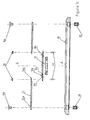
- the mass represented on the figure 1 comprises a board 10 comprising a central portion 10a of generally annular shape, provided with a central opening 10b for receiving a bearing 12 partially shown, for example a ball bearing, and arms 10c extending radially outwardly.
- the central opening 10b is circular, defined by a circle of axis AA.
- the plate 10 In its central portion 10a, the plate 10 carries, arranged in a ring, threaded rods 13 intended to secure the bearing 12 by means of bolts 14.
- the arms 10c are connected by an annular portion 10d of center disposed on the axis A-A. It is provided with three holes in which are engaged screws 16a.
- An inertia sector 18, in the form of an annular portion, is provided with five threaded feet 20. It is fixed to the board 10 by means of the screws 16a engaged in three of the threaded feet 20. It is advantageously made of heavy material, for example example in gold or platinum in high-end watches, brass for more common products. It extends over an angle of about 180 °. The function of the other two threaded feet 20 will be specified later.
- the board 10 is secured to the sector 18 only at an angle of about 90 °, by its annular portion 10d.
- the edges of the arms 10c connecting the portion central 10a at the annular portion 10d are also in arcs of circles whose centers are each at one end of the sector 18, coinciding with the centers of the two other threaded feet 20. These edges each carry six threaded feet 22, distributed regularly.
- Weights 24 are mounted one on each of the end legs. They have a generally circular sector shape and comprise, at the top 24a of the sector, a cylindrical hole in which is engaged the threaded foot 20, a screw 16b ensuring the axial retention. The opposite side is provided with a finger 24b having an opening intended to be engaged in one or other of the threaded feet 22. A nut 26 is screwed on the foot 22 to maintain the weight 24 by its finger 24b.
- the inertial sector 18 and the board 10 form a first part of a mass member, and the weights 24 a second part, the center of gravity of this member being in G.
- the screws 16, the threaded feet 20 and the threaded feet 22, and the nuts 26 take the place of a fixing device, which allows or not, depending on whether its components are in a unscrewed or screwed state, the displacement of the flyweights 24 with reference to the sector of inertia 18 and the board 10.
- the threaded feet provide indexing of the weights 24, so that they can occupy a fixed number of positions.
- Torque adjustment can be performed by any watchmaker trained for this purpose. To guarantee optimal working conditions, a first adjustment can be made at the time of sale of the watch, by qualifying the person for whom it is intended with reference to its physical activities, both professional and leisure. On this basis, the instructions for use of the watch define the position in which the flyweights must be located. After a few days of wearing, it is possible to control that the chosen position is the right one. To make the adjustment, simply unscrew the screws 16b and nuts 26 to move the flyweights 24, then screw them back when these weights 24 are in the chosen position.
- weights that do not have the same characteristics.
- One of them can occupy a finite number n of positions, defined such that the passage from one to the other of them results in a radial displacement of the center of gravity of a value .DELTA.G.
- the second weight is arranged so as to occupy a number m of positions whose passage from one to the other of them generates a radial displacement of the center of gravity of a value ⁇ g.
- the weights are dimensioned so that the product m. ⁇ g is substantially equal to ⁇ G. In this way, it is possible to make an accurate correction.
- the adjustment can be made particularly easy in a watch with a power reserve. It is then sufficient to establish a correlation between the displacement of the weights and the degree of winding of the spring.
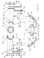
- This mass comprises first and second parts 32 and 34 each comprising a plate and a sector of inertia respectively referenced 36 and 38 for the first part 32, 40 and 42 for the second part 34.
- the boards 36 and 40 have a generally circular sector shape, with an apex angle of approximately 45 °.
- the top portion is cut to form an annular portion identified by the letter a , embracing an angle of about 200 ° for the portion 36a and about 90 ° for the portion 40a, as can be seen on the Figure 2c .
- These portions are pierced with holes identified by the letter b , three oblong holes in the portion 36a and two cylindrical holes in the portion 40a.
- the two boards are joined to each other by means of a fixing device comprising a clamping ring 44 provided with tapped holes 44a and disposed beneath the portions 36a and 40a, a cover 46 placed above the portions 36a and 40a, provided with cylindrical holes 46a aligned with the holes 44a, and screws 48 freely engaged in the holes of the cover 46 and annular portions 36a and 40a, and clamped in the tapped holes 44a of the clamping ring 44.
- a fixing device comprising a clamping ring 44 provided with tapped holes 44a and disposed beneath the portions 36a and 40a, a cover 46 placed above the portions 36a and 40a, provided with cylindrical holes 46a aligned with the holes 44a, and screws 48 freely engaged in the holes of the cover 46 and annular portions 36a and 40a, and clamped in the tapped holes 44a of the clamping ring 44.
- the board 36 is provided with oblong holes, it is possible to move it angularly with reference to the board 40, around an axis corresponding to the pivot axis AA of the mass, if the screws 48 are loosened.
- the boards 36 and 40 are each pierced with three holes identified by the letter c , practiced on the periphery of the circle sector. Their function will be specified later,
- the sectors of inertia 38 and 42 each comprise an annular portion, identified by the letter a and embracing an angle of about 80 °, and a bearing surface b attached to the annular portion a in its concave portion.
- the span b which extends about 45, serves as support for the board. It is provided with two cylindrical holes identified by the letter c , in which are engaged, for each of them, a clamping pin 50, which is provided with a threaded hole.
- Two screws 52 are engaged in two of the holes c of the boards 36 and 40 and in the tenons 50 in which they are tightened.
- the boards 36 and 40 are, in this way, respectively integral sectors 38 and 42.
- the sectors 38 and 42 could also be made of a part respectively with the boards 36 and 40, or welded to each other.
- the fixing device further comprises a stiffening arm 54, in the form of an annular portion embracing an angle of about 90 °, disposed in the extension of the bearing surfaces 38b and 42b.
- This arm comprises two oblong openings 54a each disposed facing the third hole of the boards.
- a screw 56 cooperating with a nut 58, is engaged in each of these holes and in the holes 36c and 40c not occupied by the screws 52, so that by tightening the screw and its nut, it is possible to rigidly in solidarity with both parties.
- the mass according to the invention has two moving parts one with reference to the other, their displacement inducing a radial position change of its center of gravity, it is possible to optimize the working conditions automatic watches, and thus obtain optimal performance for a minimum volume, and whatever the conditions imposed by the wearer.
Landscapes
- Physics & Mathematics (AREA)
- General Physics & Mathematics (AREA)
- Toys (AREA)
- Electric Clocks (AREA)
- Golf Clubs (AREA)
- Apparatuses For Generation Of Mechanical Vibrations (AREA)
Description
- La présente invention concerne les montres automatiques. Elle se rapporte plus particulièrement aux masses oscillantes.
- Les montres automatiques comportent un mouvement muni d'une base de temps, d'un rouage synchronisé par la base de temps, d'un accumulateur d'énergie, généralement un barillet, alimentant la base de temps et assurant l'entraînement du rouage, et d'un mécanisme automatique fournissant l'énergie à l'accumulateur d'énergie.
- Classiquement, ce mécanisme comprend une masse oscillante, montée pivotante sur le bâti du mouvement au moyen d'un palier, un inverseur transformant le mouvement alternatif de la masse en un mouvement de rotation dans un seul sens, et un rouage de remontoir, qui est de type démultiplicateur, entraîné par l'inverseur. Les oscillations de la masse, engendrées par les mouvements du porteur de la montre, assurent ainsi l'entraînement en rotation du rouage de remontoir, lequel coopère avec le barillet pour en armer le ressort.
- La masse oscillante est agencée pour porter un palier, par exemple un roulement à billes, qui définit un axe de rotation. Elle comporte un organe massique ayant un centre de gravité décalé par rapport à l'axe de rotation. L'organe massique est généralement conçu de manière à engendrer un couple maximum. Il est réalisé en matériau lourd, fréquemment en or ou en platine dans les montres haut de gamme. Il comprend, à sa périphérie, un secteur d'inertie définissant la part importante de sa masse, et une planche reliant le secteur au palier.
- La masse oscillante engendre un couple fonction essentiellement de la masse du secteur et de la position de son centre de gravité, en référence à l'axe de rotation. Ce couple est appliqué sur le premier mobile du rouage de remontoir par l'intermédiaire de l'inverseur. Le taux de démultiplication du train d'engrenages formant le rouage de remontoir définit le couple finalement appliqué sur le ressort de barillet.
- Le document
CH 317534 - Lorsque le porteur est une personne calme, les déplacements du bras amènent la masse en déséquilibre et c'est l'accélération terrestre g qui définit le couple. S'il s'agit d'une personne très active, les accélérations rencontrées peuvent être sensiblement plus élevées. Actuellement, les mécanismes de remontoir sont choisis de manière à ce qu'ils assurent des conditions d'armage du ressort pour une personne normalement active. Il en résulte qu'avec un porteur très actif le ressort de barillet est fortement sollicité et un risque d'usure ne peut être exclu. Si, au contraire, le porteur est très calme, le ressort de barillet n'est pas suffisamment armé.
- La présente invention, comme défini par les revendications, a pour but de permettre la prise en compte des spécificités du porteur pour améliorer les conditions de remontage. A cet effet, l'organe massique comporte :
- ■ deux parties amovibles l'une en référence à l'autre, et agencées de manière telle que leur déplacement relatif engendre un déplacement radial du centre de gravité de l'organe massique, et
- ■ un dispositif de fixation, coopérant avec les première et deuxième parties, susceptible d'occuper un premier état dans lequel lesdites parties peuvent être déplacées l'une en référence à l'autre, et un deuxième état dans lequel lesdites parties sont fixés rigidement l'une à l'autre.
- Grâce au fait que les deux parties peuvent être déplacées l'une par rapport à l'autre et, avec elles le centre de gravité de la masse, il est possible de faire varier les conditions de travail du mécanisme et l'adapter ainsi au mode de vie du porteur.
- De manière avantageuse, la première partie de la masse oscillante comporte, en outre, une planche, agencée pour porter le palier, et un secteur d'inertie. Cette planche s'étend du centre, lequel est muni d'un trou dans lequel est engagé le palier, vers la périphérie qui porte le secteur d'inertie. Certaines masses comportent un secteur d'inertie rapporté, alors que d'autres sont faites d'une pièce.
- Dans un premier mode de réalisation, la deuxième partie est formée d'au moins une masselotte montée pivotante sur le secteur. De plus, le dispositif de fixation comporte des moyens d'indexage agencés pour positionner la masselotte dans un nombre fini de positions prédéfinies dans lesquelles le dispositif de fixation assure le maintien de la masselotte lorsqu'il se trouve dans son deuxième état, alors qu'il permet le passage de l'une à l'autre de ces positions lorsqu'il se trouve dans son premier état.
- Afin d'augmenter la plage de correction et/ou la précision de cette correction, la deuxième partie comporte deux masselottes.
- Dans une variante permettant une grande précision de réglage, l'une des masselottes peut occuper un nombre n fini de positions définies de manière à ce que le passage de ladite masselotte de l'une à l'autre d'entres elles engendre un déplacement radial du centre de gravité d'une valeur ΔG, et en ce que la deuxième masselotte est agencée de manière à pouvoir occuper un nombre m de positions dont le passage de l'une à l'autre d'entre elles engendre un déplacement radial du centre de gravité d'une valeur Δg, lesdites masselottes étant agencées de manière à ce que le produit m.Δg est sensiblement égal à ΔG. De la sorte, il est possible de définir m.n positions de réglage, tout en évitant que les moyens d'indexage ne soient trop complexes.
- Dans ce mode de réalisation, le moment d'inertie de la masse diminue avec le couple engendré.
- Dans un deuxième mode de réalisation, la deuxième partie de la masse comprend également une planche et un secteur d'inertie, disposés côte à côte respectivement de la planche et du secteur de la première partie. En outre, le dispositif de fixation est agencé de manière à permettre un déplacement relatif de la deuxième partie en référence à la première partie par rotation autour de l'axe de la masse oscillante.
- D'autres avantages et caractéristiques de l'invention ressortiront de la description qui va suivre, faite en regard du dessin annexé, dans lequel:
- ■ Les
figures 1 et2 représentent des masses oscillantes, selon respectivement un premier mode et un deuxième mode de réalisation de l'invention, vues de dessus en a, vues en coupe en b, et en éclaté en c. - La masse représentée sur la
figure 1 comporte une planche 10 comprenant une portion centrale 10a de forme générale annulaire, munie d'une ouverture centrale 10b destinée à recevoir un palier 12 partiellement représenté, par exemple un roulement à billes, et des bras 10c s'étendant radialement vers l'extérieur. L'ouverture centrale 10b est circulaire, définie par un cercle d'axe A-A. - Dans sa portion centrale 10a, la planche 10 porte, disposées en anneau, des tiges filetées 13 destinées à assurer la fixation du palier 12 au moyen de boulons 14.
- A leur périphérie, les bras 10c sont reliés par une portion annulaire 10d de centre disposé sur l'axe A-A. Elle est munie de trois trous dans lesquelles sont engagées des vis 16a.
- Un secteur d'inertie 18, en forme de portion annulaire, est muni de cinq pieds taraudés 20. Il est fixé à la planche 10 au moyen des vis 16a engagées dans trois des pieds taraudés 20. Il est avantageusement réalisé en matériau lourd, par exemple en or ou en platine dans les montres de haut de gamme, en laiton pour des produits plus courants. Il s'étend sur un angle d'environ 180°. La fonction des deux autres pieds taraudés 20 sera précisée plus loin.
- La planche 10 n'est solidaire du secteur 18 que sur un angle de 90° environ, par sa portion annulaire 10d. Les bords des bras 10c reliant la portion centrale 10a à la portion annulaire 10d sont également en arcs de cercles dont les centres se trouvent chacun à l'une des extrémités du secteur 18, confondus avec les centres des deux autres pieds taraudés 20. Ces bords portent chacun six pieds filetés 22, répartis régulièrement.
- Des masselottes 24 sont montées une sur chacun des pieds 20 d'extrémités. Elles présentent une forme générale de secteur de cercle et comportent, au sommet 24a du secteur, un trou cylindrique dans lequel est engagé le pied taraudé 20, une vis 16b assurant le maintien axial. Le côté opposé est muni d'un doigt 24b comportant une ouverture destinée à être engagée dans l'un ou l'autre des pieds filetés 22. Un écrou 26 est vissé sur le pied 22 pour maintenir la masselotte 24 par son doigt 24b.
- Dans cette masse oscillante, le secteur d'inertie 18 et la planche 10 forment une première partie d'un organe massique, et les masselottes 24 une deuxième partie, le centre de gravité de cet organe se trouvant en G. Les vis 16, les pieds taraudés 20 et les pieds filetés 22, ainsi que les écrous 26 tiennent lieu de dispositif de fixation, lequel permet ou non, selon que ses constituants sont dans un état dévissé ou vissé, le déplacement des masselottes 24 en référence au secteur d'inertie 18 et à la planche 10. En outre, les pieds filetés assurent un indexage des masselottes 24, de telle sorte que celles-ci peuvent occuper un nombre déterminé de positions.
- Avec la masse ainsi décrite, il est possible de faire varier de quelques pourcent le couple qu'elle applique sur le rouage en vue d'assurer le remontage du ressort moteur de la montre. Il suffit de modifier la position d'une ou des deux masselottes 24. Le centre de gravité G est d'autant plus décalé par rapport à l'axe A-A et, en conséquence, le couple est d'autant plus grand que les extrémités munies du doigt 24b des masselottes 24 se trouvent au voisinage du secteur 18. Au contraire, en ramenant le doigt 24b de manière à ce qu'il soit engagé dans un pied 22 voisin de la portion centrale 10a, le centre de gravité est décalé vers l'axe A-A, de telle sorte que le couple est réduit.
- L'ajustement du couple peut être réalisé par n'importe quel horloger formé à cet effet. Pour garantir des conditions optimales de travail, un premier réglage peut être fait au moment de la vente de la montre, en qualifiant la personne à qui elle est destinée en référence à ses activités physiques, tant professionnelles que de loisir. Sur cette base, le mode d'emploi de la montre définit la position dans laquelle doivent se trouver les masselottes. Après quelques jours de porter, il est possible de contrôler que la position choisie est la bonne. Pour effectuer le réglage, il suffit de dévisser les vis 16b et les écrous 26 pour pouvoir déplacer les masselottes 24, puis les revisser lorsque ces masselottes 24 se trouvent dans la position choisie.
- Afin d'assurer un réglage le plus précis possible, il est envisageable de disposer de masselottes n'ayant pas les mêmes caractéristiques. L'une d'elles peut occuper un nombre n fini de positions, définies de manière à ce que le passage de l'une à l'autre d'entre elles engendre un déplacement radial du centre de gravité d'une valeur ΔG. La deuxième masselotte est agencée de manière à pouvoir occuper un nombre m de positions dont le passage de l'une à l'autre d'entre elles engendre un déplacement radial du centre de gravité d'une valeur Δg. Les masselottes sont dimensionnées de manière à ce que le produit m.Δg soit sensiblement égal à ΔG. De la sorte, il est possible d'effectuer une correction précise.
- Le mode de réalisation décrit ci-dessus ne doit que peu être modifié pour atteindre ce résultat. Il suffit que les dimensions (épaisseur, longueur notamment) de l'une des masselottes soient réduites de manière adéquate pour obtenir l'effet recherché. Cette opération est facilement accessible à l'homme du métier.
- Le réglage peut se faire de manière particulièrement aisée dans une montre munie d'une réserve de marche. Il suffit alors d'établir une corrélation entre le déplacement des masselottes et le degré d'armage du ressort.
- Dans le mode de réalisation décrit en référence à la
figure 1 , le moment d'inertie augmente en même temps qu'est déplacé le centre de gravité de la masse. Il est également possible de changer la position du centre de gravité tout en gardant le même moment d'inertie. C'est ce que permet le mode de réalisation représenté à lafigure 2 , qui montre une masse vue en plan en a et en coupe en b et en éclaté en c. - Cette masse comporte des première et deuxième parties 32 et 34 comprenant chacune une planche et un secteur d'inertie, respectivement référencés 36 et 38 pour la première partie 32, 40 et 42 pour la deuxième partie 34.
- Les planches 36 et 40 présentent une forme générale de secteur de cercle, d'angle au sommet environ égal à 45°. La partie sommitale est découpée pour former une portion annulaire identifiée par la lettre a, embrassant un angle d'environ 200° pour la portion 36a et d'environ 90° pour la portion 40a, comme on peut le voir sur la
figure 2c . Ces portions sont percées de trous identifiés par la lettre b, trois trous oblongs dans la portion 36a et deux trous cylindriques dans la portion 40a. - Les deux planches sont assemblées l'une à l'autre au moyen d'un dispositif de fixation comportant une bague de serrage 44 munie de trous taraudés 44a et disposée en-dessous des portions 36a et 40a, un couvercle 46 placé au-dessus des portions 36a et 40a, muni de trous cylindriques 46a alignés sur les trous 44a, et des vis 48 engagées librement dans les trous du couvercle 46 et des portions annulaires 36a et 40a, et serrées dans les trous taraudés 44a de la bague de serrage 44.
- Comme la planche 36 est munie de trous oblongs, il est possible de la déplacer angulairement en référence à la planche 40, autour d'un axe correspondant à l'axe de pivotement A-A de la masse, si les vis 48 sont desserrées.
- Les planches 36 et 40 sont percées chacune de trois trous identifiés par la lettre c, pratiqués à la périphérie du secteur de cercle. Leur fonction sera précisée plus loin,
- Les secteurs d'inertie 38 et 42 comprennent chacun une portion annulaire, identifiée par la lettre a et embrassant un angle de 80° environ, et une portée b attachée à la portion annulaire a dans sa partie concave. La portée b, qui s'étend sur environ 45 , sert d'appui à la planche. Elle est munie de deux trous cylindriques identifiés par la lettre c, dans lesquels sont engagés, pour chacun d'eux, un tenon de serrage 50, lequel est muni d'un trou taraudé. Deux vis 52 sont engagées dans deux des trous c des planches 36 et 40 et dans les tenons 50 dans lesquels elles sont serrées. Les planches 36 et 40 sont, de la sorte, respectivement solidaires des secteurs 38 et 42.
- En variante, les secteurs 38 et 42 pourraient aussi être réalisés d'une pièce respectivement avec les planches 36 et 40, ou soudés l'un à l'autre.
- Avec la structure telle qu'elle vient d'être décrite, il se peut que les planches 36 et 40 manquent de rigidité. Aussi, pour rendre mieux solidaires les deux parties, le dispositif de fixation comporte, en outre, un bras de rigidification 54, en forme de portion annulaire embrassant un angle de 90° environ, disposé dans le prolongement des portées 38b et 42b. Ce bras comprend deux ouvertures oblongues 54a disposées chacune en regard du troisième trou des planches. Une vis 56, coopérant avec un écrou 58, est engagée dans chacun de ces trous et dans les trous 36c et 40c non occupés par les vis 52, de telle sorte qu'en serrant la vis et son écrou, il est possible de rendre rigidement solidaires les deux parties.
- De nombreuses variantes aux deux modes de réalisations décrits ci-dessus sont, bien entendu, envisageables. Les solutions décrites font largement appel aux vis, ce qui est une solution particulièrement simple à mettre en oeuvre pour la réalisation de pièces uniques ou de prototypes. Dans le cas d'une production à grande échelle il serait envisageable d'utiliser d'autres systèmes de verrouillage, à cran par exemple, ou par tout autre moyen connu de l'homme du métier. Les deux parties constitutives de la masse pourraient aussi présenter des formes très différentes, et avoir des rapports dimensionnels variant considérablement, en fonction du déplacement relatif possible et de la plage de réglage souhaitée.
- Il serait également possible de construire une masse selon le deuxième mode de réalisation munie d'une masselotte telle que définie dans le premier mode de réalisation, de manière à permettre un ajustement grossier avec un déplacement relatif des deux parties, puis plus fin en réglant la position de la masselotte.
- Ainsi, grâce au fait que la masse selon l'invention présente deux parties mobiles l'une en référence à l'autre, leur déplacement induisant un changement de position radiale de son centre de gravité, il est possible d'optimiser les conditions de travail des montres automatiques, et ainsi obtenir un rendement optimal pour un volume minimum, et quelles que soient les conditions imposées par le porteur.
Claims (6)
- Masse oscillante pour montre automatique, agencée pour porter un palier (12) définissant un axe de rotation (A-A) et destiné à être monté sur le bâti de la montre, comportant un organe massique ayant un centre de gravité (G) décalé par rapport à l'axe de rotation, ledit organe comportant deux parties amovibles l'une (10, 18 ; 32) en référence à l'autre (24 ;34), et agencées de manière telle que leur déplacement relatif engendre un déplacement radial du centre de gravité (G) de l'organe massique, caractérisée en ce que ledit organe comporte un dispositif de fixation (13, 14, 16b ; 44, 46, 48, 54, 56), coopérant avec les première et deuxième parties, susceptible d'occuper un premier état dans lequel lesdites parties peuvent être déplacées l'une en référence à l'autre, et un deuxième état dans lequel lesdites parties sont fixées rigidement les unes aux autres.
- Masse oscillante selon la revendication 1, caractérisée en ce que ladite première partie comporte une planche (10) agencée pour porter ledit palier (12) et un secteur d'inertie (18) fixé rigidement à la planche (10).
- Masse oscillante selon la revendication 2, caractérisée en ce que ladite deuxième partie est formée d'au moins une masselotte (24) montée pivotante sur ledit secteur (18) et en ce que ledit dispositif de fixation comporte des moyens d'indexage (22) agencés pour positionner ladite masselotte dans un nombre fini de positions prédéfinies dans lesquelles ledit dispositif assure le maintien de ladite masselotte lorsqu'il se trouve dans son deuxième état, alors qu'il permet le passage de l'une à l'autre de ces positions lorsqu'il se trouve dans son premier état.
- Masse oscillante selon la revendication 3, caractérisée en ce que la deuxième partie comporte deux masselottes (24).
- Masse oscillante selon la revendication 4, caractérisée en ce que l'une des masselottes (24) peut occuper un nombre n fini de positions, définies de manière à ce que le passage de l'une à l'autre d'entres elles engendre un déplacement radial du centre de gravité (G) d'une valeur ΔG, et en ce que la deuxième masselotte (24) est agencée de manière à pouvoir occuper un nombre m de positions dont le passage de l'une à l'autre d'entre elles engendre un déplacement radial du centre de gravité d'une valeur Δg, lesdites masselottes (24) étant agencées de manière à ce que le produit m.Δg est sensiblement égal à ΔG.
- Masse oscillante selon la revendication 2, caractérisée en ce que ladite deuxième partie (34) comprend également une planche (40) et un secteur d'inertie (42), disposés côte à côte respectivement avec la planche (36) et le secteur (38) de la première partie (32), et en ce que le dispositif de fixation est agencé de manière à permettre, dans son premier état, un déplacement angulaire relatif de la deuxième partie (34) en référence à la première partie (32) par rotation autour dudit axe (A-A).
Priority Applications (8)
| Application Number | Priority Date | Filing Date | Title |
|---|---|---|---|
| EP03405056A EP1445668B1 (fr) | 2003-02-04 | 2003-02-04 | Masse oscillante |
| DE60328353T DE60328353D1 (de) | 2003-02-04 | 2003-02-04 | Schwungmasse |
| KR1020057014224A KR101016252B1 (ko) | 2003-02-04 | 2004-02-04 | 회전추 |
| JP2006502440A JP4334566B2 (ja) | 2003-02-04 | 2004-02-04 | 回転錘 |
| PCT/IB2004/000400 WO2004070478A2 (fr) | 2003-02-04 | 2004-02-04 | Masse oscillante |
| CNB2004800034286A CN100430842C (zh) | 2003-02-04 | 2004-02-04 | 摆锤 |
| US10/541,287 US7217030B2 (en) | 2003-02-04 | 2004-02-04 | Oscillating weight |
| HK04110228.9A HK1067718B (en) | 2004-12-24 | Oscillating weight |
Applications Claiming Priority (1)
| Application Number | Priority Date | Filing Date | Title |
|---|---|---|---|
| EP03405056A EP1445668B1 (fr) | 2003-02-04 | 2003-02-04 | Masse oscillante |
Publications (2)
| Publication Number | Publication Date |
|---|---|
| EP1445668A1 EP1445668A1 (fr) | 2004-08-11 |
| EP1445668B1 true EP1445668B1 (fr) | 2009-07-15 |
Family
ID=32605482
Family Applications (1)
| Application Number | Title | Priority Date | Filing Date |
|---|---|---|---|
| EP03405056A Expired - Lifetime EP1445668B1 (fr) | 2003-02-04 | 2003-02-04 | Masse oscillante |
Country Status (7)
| Country | Link |
|---|---|
| US (1) | US7217030B2 (fr) |
| EP (1) | EP1445668B1 (fr) |
| JP (1) | JP4334566B2 (fr) |
| KR (1) | KR101016252B1 (fr) |
| CN (1) | CN100430842C (fr) |
| DE (1) | DE60328353D1 (fr) |
| WO (1) | WO2004070478A2 (fr) |
Families Citing this family (21)
| Publication number | Priority date | Publication date | Assignee | Title |
|---|---|---|---|---|
| USD539182S1 (en) * | 2005-03-11 | 2007-03-27 | Perrelet Sa | Oscillating weight for wristwatches |
| CH699825B1 (fr) * | 2006-07-05 | 2010-05-14 | Marco Danzinelli | Montre automatique. |
| DE602006004465D1 (de) * | 2006-10-31 | 2009-02-05 | Swatch Group Man Serv Ag | Schwingmasse zum Wiederaufladen der Energiequelle eines tragbaren Instruments |
| EP2110719B1 (fr) * | 2008-04-15 | 2012-02-01 | Montres Jaquet Droz SA | Amortisseur de choc pour masse oscillante |
| EP2228693B1 (fr) * | 2009-03-13 | 2013-03-13 | Bulgari Horlogerie S.A. | Dispositif de fixation pour timbres d'une montre a sonnerie |
| USD640582S1 (en) * | 2009-12-01 | 2011-06-28 | Lvmh Swiss Manufactures S.A. | Weight |
| CH703577B1 (fr) * | 2011-03-23 | 2015-10-15 | Christian Dior Couture Sa | Masse oscillante pour montre automatique et montre automatique comportant une telle masse. |
| JP5731872B2 (ja) * | 2011-03-30 | 2015-06-10 | セイコーインスツル株式会社 | 時計用回転錘およびその回転錘を備えた時計 |
| EP2592498A1 (fr) * | 2011-11-08 | 2013-05-15 | ETA SA Manufacture Horlogère Suisse | Masse oscillante |
| CH706000B1 (fr) * | 2012-01-13 | 2023-09-15 | Christian Dior Couture Sa | Masse de remontage. |
| WO2013141493A1 (fr) * | 2012-03-20 | 2013-09-26 | Son Se Ik | Rotor pour mouvement de montre |
| USD772095S1 (en) * | 2014-07-16 | 2016-11-22 | Richemont International Sa | Oscillating weight |
| USD725530S1 (en) * | 2014-11-04 | 2015-03-31 | Graff Diamonds Sa | Watch rotor |
| USD892666S1 (en) * | 2018-01-05 | 2020-08-11 | Harry Winston Sa | Oscillating weight |
| TWD199031S (zh) * | 2018-02-20 | 2019-08-11 | 瑞士商哈利溫士頓公司 | 錶殼 |
| CH715510A1 (fr) * | 2018-11-02 | 2020-05-15 | Guenat Sa Montres Valgine | Masse oscillante à géométrie variable pour mécanisme horloger. |
| EP3879354B1 (fr) * | 2020-03-09 | 2025-07-30 | The Swatch Group Research and Development Ltd | Masse de remontage oscillante munie d'un element decoratif pour mouvement automatique de pièce d'horlogerie |
| CN111665706B (zh) * | 2020-07-03 | 2021-03-30 | 郑君雄 | 一种自动上弦且可以受到震动发出警报的老人手表 |
| USD982468S1 (en) * | 2022-02-28 | 2023-04-04 | Cartier International Ag | Watch dial |
| USD1079489S1 (en) * | 2023-05-19 | 2025-06-17 | Omega Sa | Watch case |
| WO2025190470A1 (fr) | 2024-03-11 | 2025-09-18 | Sarl Manufacture Dominique Renaud | Mouvement horloger comprenant un mécanisme de remontage automatique |
Family Cites Families (9)
| Publication number | Priority date | Publication date | Assignee | Title |
|---|---|---|---|---|
| CH317534A (fr) * | 1954-05-06 | 1956-11-30 | Bueren Watch Company S A | Masse pour montre à remontage automatique |
| US2988869A (en) * | 1958-03-26 | 1961-06-20 | Buren Watch Company S A | Self-winding watch |
| CH590505B5 (fr) * | 1975-05-30 | 1977-08-15 | Ebauchesfabrik Eta Ag | |
| JP2582155B2 (ja) * | 1989-04-25 | 1997-02-19 | シチズン時計株式会社 | 自動巻用オモリ |
| CN2149643Y (zh) * | 1993-01-01 | 1993-12-15 | 王文君 | 超薄型机械自动手表 |
| JP3686123B2 (ja) * | 1995-06-22 | 2005-08-24 | ペルレ ソシエテ アノニム | 時計の自動ぜんまい巻き装置 |
| EP0957414B1 (fr) * | 1998-05-07 | 2003-02-12 | Janvier S.A. | Masse de remontage oscillante pour pièce d'horlogerie à mouvement automatique et pièce d'horlogerie équipée d'une telle masse de remontage |
| JP2000065962A (ja) * | 1998-08-19 | 2000-03-03 | Seiko Epson Corp | 回転錘、時計、および回転錘の製造方法 |
| EP1046965B1 (fr) * | 1999-04-23 | 2004-08-18 | Rolex Sa | Montre à remontage automatique |
-
2003
- 2003-02-04 EP EP03405056A patent/EP1445668B1/fr not_active Expired - Lifetime
- 2003-02-04 DE DE60328353T patent/DE60328353D1/de not_active Expired - Lifetime
-
2004
- 2004-02-04 CN CNB2004800034286A patent/CN100430842C/zh not_active Expired - Lifetime
- 2004-02-04 KR KR1020057014224A patent/KR101016252B1/ko not_active Expired - Lifetime
- 2004-02-04 US US10/541,287 patent/US7217030B2/en not_active Expired - Lifetime
- 2004-02-04 WO PCT/IB2004/000400 patent/WO2004070478A2/fr not_active Ceased
- 2004-02-04 JP JP2006502440A patent/JP4334566B2/ja not_active Expired - Fee Related
Also Published As
| Publication number | Publication date |
|---|---|
| HK1067718A1 (en) | 2005-04-15 |
| KR20050095884A (ko) | 2005-10-04 |
| US7217030B2 (en) | 2007-05-15 |
| WO2004070478A2 (fr) | 2004-08-19 |
| JP4334566B2 (ja) | 2009-09-30 |
| JP2006517294A (ja) | 2006-07-20 |
| DE60328353D1 (de) | 2009-08-27 |
| EP1445668A1 (fr) | 2004-08-11 |
| US20060050617A1 (en) | 2006-03-09 |
| CN1748185A (zh) | 2006-03-15 |
| WO2004070478A3 (fr) | 2004-11-25 |
| CN100430842C (zh) | 2008-11-05 |
| KR101016252B1 (ko) | 2011-02-25 |
Similar Documents
| Publication | Publication Date | Title |
|---|---|---|
| EP1445668A1 (fr) | Masse oscillante | |
| EP2998800B1 (fr) | Composant horloger à pivot flexible | |
| EP1941326B1 (fr) | Echappement a detente pour piece d'horlogerie | |
| EP2690507B1 (fr) | Spiral d'horlogerie | |
| CH702707B1 (fr) | Mouvement de pièce d'horlogerie à tourbillon. | |
| EP3172626B1 (fr) | Pivot à lame | |
| CH708525B1 (fr) | Mécanisme de stabilisation du fonctionnement du balancier-spiral, mouvement horloger et montre mécanique. | |
| CH705238A2 (fr) | Balancier à réglage d'inertie pour mouvement d'horlogerie. | |
| EP4194964B1 (fr) | Balancier à reglage d'inertie | |
| EP1804143B1 (fr) | Pièce d'horlogerie mécanique comprenant des moyens de réglage de l'ébat d'un mobile tournant | |
| EP3874331B1 (fr) | Masse oscillante à géométrie variable pour mécanisme horloger | |
| EP2506093B1 (fr) | Balancier pour mouvement d'horlogerie | |
| EP1944662A1 (fr) | Mécanisme de sonnerie des heures | |
| EP2798414B1 (fr) | Ressort pour mouvement horloger | |
| EP2096504A2 (fr) | Mécanisme d'affichage des secondes mortes | |
| WO2013104941A1 (fr) | Piece d'horlogerie a remontage automatique | |
| EP3629100B1 (fr) | Dispositif de guidage symetrique de deux elements, notamment pour l'horlogerie | |
| EP1960846B1 (fr) | Mouvement d'horlogerie | |
| EP3783444B1 (fr) | Mécanisme horloger comprenant un dispositif de blocage | |
| EP4575668A1 (fr) | Ensemble d'horlogerie pour organe réglant muni de moyens d'ajustement de la marche | |
| CH701239A2 (fr) | Mecanisme de remontage automatique pour mouvement horloger. | |
| CH712013B1 (fr) | Mécanisme horloger à force constante. | |
| CH721309A2 (fr) | Carrousel d'horlogerie comprenant deux roulements à billes | |
| CH721430A2 (fr) | Ensemble d'horlogerie pour organe réglant muni de moyens d'ajustement de la marche | |
| CH720982A2 (fr) | Organe réglant d'horlogerie comprenant un système d'actionnement muni d'une bascule de commande |
Legal Events
| Date | Code | Title | Description |
|---|---|---|---|
| PUAI | Public reference made under article 153(3) epc to a published international application that has entered the european phase |
Free format text: ORIGINAL CODE: 0009012 |
|
| AK | Designated contracting states |
Kind code of ref document: A1 Designated state(s): AT BE BG CH CY CZ DE DK EE ES FI FR GB GR HU IE IT LI LU MC NL PT SE SI SK TR |
|
| AX | Request for extension of the european patent |
Extension state: AL LT LV MK RO |
|
| 17P | Request for examination filed |
Effective date: 20050104 |
|
| REG | Reference to a national code |
Ref country code: HK Ref legal event code: DE Ref document number: 1067718 Country of ref document: HK |
|
| AKX | Designation fees paid |
Designated state(s): AT BE BG CH CY CZ DE DK EE ES FI FR GB GR HU IE IT LI LU MC NL PT SE SI SK TR |
|
| GRAP | Despatch of communication of intention to grant a patent |
Free format text: ORIGINAL CODE: EPIDOSNIGR1 |
|
| GRAS | Grant fee paid |
Free format text: ORIGINAL CODE: EPIDOSNIGR3 |
|
| GRAA | (expected) grant |
Free format text: ORIGINAL CODE: 0009210 |
|
| AK | Designated contracting states |
Kind code of ref document: B1 Designated state(s): AT BE BG CH CY CZ DE DK EE ES FI FR GB GR HU IE IT LI LU MC NL PT SE SI SK TR |
|
| REG | Reference to a national code |
Ref country code: CH Ref legal event code: EP Ref country code: GB Ref legal event code: FG4D Free format text: NOT ENGLISH |
|
| REG | Reference to a national code |
Ref country code: IE Ref legal event code: FG4D |
|
| REF | Corresponds to: |
Ref document number: 60328353 Country of ref document: DE Date of ref document: 20090827 Kind code of ref document: P |
|
| REG | Reference to a national code |
Ref country code: CH Ref legal event code: NV Representative=s name: GLN S.A. Ref country code: CH Ref legal event code: PCOW Free format text: VAUCHER MANUFACTURE FLEURIER S.A.;CHEMIN DU RIGHI 2;2114 FLEURIER (CH) |
|
| REG | Reference to a national code |
Ref country code: HK Ref legal event code: GR Ref document number: 1067718 Country of ref document: HK |
|
| NLV1 | Nl: lapsed or annulled due to failure to fulfill the requirements of art. 29p and 29m of the patents act | ||
| PG25 | Lapsed in a contracting state [announced via postgrant information from national office to epo] |
Ref country code: ES Free format text: LAPSE BECAUSE OF FAILURE TO SUBMIT A TRANSLATION OF THE DESCRIPTION OR TO PAY THE FEE WITHIN THE PRESCRIBED TIME-LIMIT Effective date: 20091026 Ref country code: SE Free format text: LAPSE BECAUSE OF FAILURE TO SUBMIT A TRANSLATION OF THE DESCRIPTION OR TO PAY THE FEE WITHIN THE PRESCRIBED TIME-LIMIT Effective date: 20090715 Ref country code: FI Free format text: LAPSE BECAUSE OF FAILURE TO SUBMIT A TRANSLATION OF THE DESCRIPTION OR TO PAY THE FEE WITHIN THE PRESCRIBED TIME-LIMIT Effective date: 20090715 Ref country code: AT Free format text: LAPSE BECAUSE OF FAILURE TO SUBMIT A TRANSLATION OF THE DESCRIPTION OR TO PAY THE FEE WITHIN THE PRESCRIBED TIME-LIMIT Effective date: 20090715 |
|
| REG | Reference to a national code |
Ref country code: IE Ref legal event code: FD4D |
|
| PG25 | Lapsed in a contracting state [announced via postgrant information from national office to epo] |
Ref country code: NL Free format text: LAPSE BECAUSE OF FAILURE TO SUBMIT A TRANSLATION OF THE DESCRIPTION OR TO PAY THE FEE WITHIN THE PRESCRIBED TIME-LIMIT Effective date: 20090715 Ref country code: SI Free format text: LAPSE BECAUSE OF FAILURE TO SUBMIT A TRANSLATION OF THE DESCRIPTION OR TO PAY THE FEE WITHIN THE PRESCRIBED TIME-LIMIT Effective date: 20090715 |
|
| PG25 | Lapsed in a contracting state [announced via postgrant information from national office to epo] |
Ref country code: PT Free format text: LAPSE BECAUSE OF FAILURE TO SUBMIT A TRANSLATION OF THE DESCRIPTION OR TO PAY THE FEE WITHIN THE PRESCRIBED TIME-LIMIT Effective date: 20091115 Ref country code: BG Free format text: LAPSE BECAUSE OF FAILURE TO SUBMIT A TRANSLATION OF THE DESCRIPTION OR TO PAY THE FEE WITHIN THE PRESCRIBED TIME-LIMIT Effective date: 20091015 |
|
| PG25 | Lapsed in a contracting state [announced via postgrant information from national office to epo] |
Ref country code: CZ Free format text: LAPSE BECAUSE OF FAILURE TO SUBMIT A TRANSLATION OF THE DESCRIPTION OR TO PAY THE FEE WITHIN THE PRESCRIBED TIME-LIMIT Effective date: 20090715 Ref country code: DK Free format text: LAPSE BECAUSE OF FAILURE TO SUBMIT A TRANSLATION OF THE DESCRIPTION OR TO PAY THE FEE WITHIN THE PRESCRIBED TIME-LIMIT Effective date: 20090715 Ref country code: EE Free format text: LAPSE BECAUSE OF FAILURE TO SUBMIT A TRANSLATION OF THE DESCRIPTION OR TO PAY THE FEE WITHIN THE PRESCRIBED TIME-LIMIT Effective date: 20090715 Ref country code: IE Free format text: LAPSE BECAUSE OF FAILURE TO SUBMIT A TRANSLATION OF THE DESCRIPTION OR TO PAY THE FEE WITHIN THE PRESCRIBED TIME-LIMIT Effective date: 20090715 |
|
| PLBE | No opposition filed within time limit |
Free format text: ORIGINAL CODE: 0009261 |
|
| STAA | Information on the status of an ep patent application or granted ep patent |
Free format text: STATUS: NO OPPOSITION FILED WITHIN TIME LIMIT |
|
| PG25 | Lapsed in a contracting state [announced via postgrant information from national office to epo] |
Ref country code: SK Free format text: LAPSE BECAUSE OF FAILURE TO SUBMIT A TRANSLATION OF THE DESCRIPTION OR TO PAY THE FEE WITHIN THE PRESCRIBED TIME-LIMIT Effective date: 20090715 |
|
| 26N | No opposition filed |
Effective date: 20100416 |
|
| BERE | Be: lapsed |
Owner name: VAUCHER MANUFACTURE FLEURIER SA Effective date: 20100228 |
|
| PG25 | Lapsed in a contracting state [announced via postgrant information from national office to epo] |
Ref country code: MC Free format text: LAPSE BECAUSE OF NON-PAYMENT OF DUE FEES Effective date: 20100301 Ref country code: GR Free format text: LAPSE BECAUSE OF FAILURE TO SUBMIT A TRANSLATION OF THE DESCRIPTION OR TO PAY THE FEE WITHIN THE PRESCRIBED TIME-LIMIT Effective date: 20091016 |
|
| PG25 | Lapsed in a contracting state [announced via postgrant information from national office to epo] |
Ref country code: BE Free format text: LAPSE BECAUSE OF NON-PAYMENT OF DUE FEES Effective date: 20100228 |
|
| PG25 | Lapsed in a contracting state [announced via postgrant information from national office to epo] |
Ref country code: IT Free format text: LAPSE BECAUSE OF FAILURE TO SUBMIT A TRANSLATION OF THE DESCRIPTION OR TO PAY THE FEE WITHIN THE PRESCRIBED TIME-LIMIT Effective date: 20090715 |
|
| PG25 | Lapsed in a contracting state [announced via postgrant information from national office to epo] |
Ref country code: CY Free format text: LAPSE BECAUSE OF FAILURE TO SUBMIT A TRANSLATION OF THE DESCRIPTION OR TO PAY THE FEE WITHIN THE PRESCRIBED TIME-LIMIT Effective date: 20090715 |
|
| PG25 | Lapsed in a contracting state [announced via postgrant information from national office to epo] |
Ref country code: LU Free format text: LAPSE BECAUSE OF NON-PAYMENT OF DUE FEES Effective date: 20100204 Ref country code: HU Free format text: LAPSE BECAUSE OF FAILURE TO SUBMIT A TRANSLATION OF THE DESCRIPTION OR TO PAY THE FEE WITHIN THE PRESCRIBED TIME-LIMIT Effective date: 20100116 |
|
| PG25 | Lapsed in a contracting state [announced via postgrant information from national office to epo] |
Ref country code: TR Free format text: LAPSE BECAUSE OF FAILURE TO SUBMIT A TRANSLATION OF THE DESCRIPTION OR TO PAY THE FEE WITHIN THE PRESCRIBED TIME-LIMIT Effective date: 20090715 |
|
| REG | Reference to a national code |
Ref country code: CH Ref legal event code: PCAR Free format text: NEW ADDRESS: AVENUE EDOUARD-DUBOIS 20, 2000 NEUCHATEL (CH) |
|
| REG | Reference to a national code |
Ref country code: CH Ref legal event code: PUE Owner name: HOROMETRIE SA, CH Free format text: FORMER OWNER: VAUCHER MANUFACTURE FLEURIER S.A., CH |
|
| REG | Reference to a national code |
Ref country code: GB Ref legal event code: 732E Free format text: REGISTERED BETWEEN 20140612 AND 20140618 |
|
| REG | Reference to a national code |
Ref country code: FR Ref legal event code: TP Owner name: HOROMETRIE SA, CH Effective date: 20140710 |
|
| REG | Reference to a national code |
Ref country code: DE Ref legal event code: R081 Ref document number: 60328353 Country of ref document: DE Owner name: HOROMETRIE SA, CH Free format text: FORMER OWNER: VAUCHER MANUFACTURE FLEURIER S.A., FLEURIER, CH Effective date: 20141008 |
|
| REG | Reference to a national code |
Ref country code: FR Ref legal event code: PLFP Year of fee payment: 13 |
|
| REG | Reference to a national code |
Ref country code: FR Ref legal event code: PLFP Year of fee payment: 14 |
|
| REG | Reference to a national code |
Ref country code: CH Ref legal event code: PFA Owner name: HOROMETRIE SA, CH Free format text: FORMER OWNER: HOROMETRIE SA, CH |
|
| REG | Reference to a national code |
Ref country code: FR Ref legal event code: PLFP Year of fee payment: 15 |
|
| REG | Reference to a national code |
Ref country code: FR Ref legal event code: PLFP Year of fee payment: 16 |
|
| REG | Reference to a national code |
Ref country code: CH Ref legal event code: NV Representative=s name: BOVARD SA NEUCHATEL CONSEILS EN PROPRIETE INTE, CH |
|
| PGFP | Annual fee paid to national office [announced via postgrant information from national office to epo] |
Ref country code: GB Payment date: 20220223 Year of fee payment: 20 Ref country code: DE Payment date: 20220217 Year of fee payment: 20 Ref country code: CH Payment date: 20220210 Year of fee payment: 20 |
|
| PGFP | Annual fee paid to national office [announced via postgrant information from national office to epo] |
Ref country code: FR Payment date: 20220216 Year of fee payment: 20 |
|
| REG | Reference to a national code |
Ref country code: DE Ref legal event code: R071 Ref document number: 60328353 Country of ref document: DE |
|
| REG | Reference to a national code |
Ref country code: CH Ref legal event code: PL |
|
| REG | Reference to a national code |
Ref country code: GB Ref legal event code: PE20 Expiry date: 20230203 |
|
| PG25 | Lapsed in a contracting state [announced via postgrant information from national office to epo] |
Ref country code: GB Free format text: LAPSE BECAUSE OF EXPIRATION OF PROTECTION Effective date: 20230203 |