EP1445518A1 - Kolbenring - Google Patents
Kolbenring Download PDFInfo
- Publication number
- EP1445518A1 EP1445518A1 EP03027235A EP03027235A EP1445518A1 EP 1445518 A1 EP1445518 A1 EP 1445518A1 EP 03027235 A EP03027235 A EP 03027235A EP 03027235 A EP03027235 A EP 03027235A EP 1445518 A1 EP1445518 A1 EP 1445518A1
- Authority
- EP
- European Patent Office
- Prior art keywords
- ring
- piston ring
- piston
- webs
- ring according
- Prior art date
- Legal status (The legal status is an assumption and is not a legal conclusion. Google has not performed a legal analysis and makes no representation as to the accuracy of the status listed.)
- Granted
Links
Images


Classifications
-
- F—MECHANICAL ENGINEERING; LIGHTING; HEATING; WEAPONS; BLASTING
- F16—ENGINEERING ELEMENTS AND UNITS; GENERAL MEASURES FOR PRODUCING AND MAINTAINING EFFECTIVE FUNCTIONING OF MACHINES OR INSTALLATIONS; THERMAL INSULATION IN GENERAL
- F16J—PISTONS; CYLINDERS; SEALINGS
- F16J9/00—Piston-rings, e.g. non-metallic piston-rings, seats therefor; Ring sealings of similar construction
- F16J9/12—Details
- F16J9/14—Joint-closures
-
- F—MECHANICAL ENGINEERING; LIGHTING; HEATING; WEAPONS; BLASTING
- F16—ENGINEERING ELEMENTS AND UNITS; GENERAL MEASURES FOR PRODUCING AND MAINTAINING EFFECTIVE FUNCTIONING OF MACHINES OR INSTALLATIONS; THERMAL INSULATION IN GENERAL
- F16J—PISTONS; CYLINDERS; SEALINGS
- F16J9/00—Piston-rings, e.g. non-metallic piston-rings, seats therefor; Ring sealings of similar construction
- F16J9/12—Details
- F16J9/22—Rings for preventing wear of grooves or like seatings
Definitions
- the invention relates to a piston ring according to the Preamble of claim 1 specified type.
- a piston ring is used to seal a Annular gap between the piston and one him improve surrounding jack.
- Essential feature a piston ring is a parting line that adjusts itself a circumferential point across the ring body of the Ring piston extends, whereby two ring ends of the Piston ring are formed. In the field of The ring ends can be divided by tapered webs radially and / or axially overlap what is form a Z-shaped dividing line leaves.
- a piston ring described so far is suitable for an axially reciprocating piston, as in an Otto engine is the case for rotating pistons that z. B. in a gearbox through shafts or hollow shafts can be formed, and for stationary pistons that z. B. can be formed by axes.
- the piston ring in operation Walk circumferentially. With a rotating piston can also do such walking in the circumferential direction the piston friction can be caused with the bush.
- An existing piston ring is not only subject to its circumference but also on its side surfaces wear, especially in the area of its ring ends.
- the invention has for its object a Piston ring according to the preamble of claim 1 specified type in such a way that under Avoiding the disadvantages mentioned Susceptibility to wear on at least one side surface is reduced and its lifespan is increased.
- the invention is based on the knowledge that that the wear of the piston ring side surfaces especially in the area of the ring ends by a improved lubrication can be reduced. To the others are based on the knowledge that that at the dividing line in the side surfaces leaking gap spacing the lubrication deteriorate because of their side edges especially with a relative rotational movement between a lubricating film on the piston and the piston ring affect.
- a recessed open space is provided, each from the side surface towards the associated one
- the end of the ring extends and ends at the end of the ring.
- the Open space runs out at the associated ring end. hereby becomes a lubrication pocket open towards the end of the ring formed in which the lubricant collect well and also well delivered to the side surface of the piston ring can be.
- the configuration according to the invention leads to only limited a seal of the piston barrel gap. A particular Leakage is allowed and for lubrication and Oil film formation on the axial effective or sliding surface of the Piston ring desired. It can be done Prevent or minimize pressure drops.
- the configuration according to the invention is suitable for Piston rings of different pistons, e.g. B. also for Cylinder pistons for Otto engines.
- the configuration according to the invention is suitable especially good for a piston ring on a Piston is mounted, which rotates in operation. in this connection can cause the piston ring to twist with respect to the Pistons come, e.g. B. when the piston ring due to its friction with the socket surrounding it is not rotated or rotated less than the piston.
- the free space can also on the outer circumference of the Leak the piston ring.
- a piston ring With a piston ring, the ring ends of which coincide with radially overlap tapered webs, extend the webs each in one receiving groove of the other Ringendes, being between the free end faces of the Webs and the opposite boundary surfaces of the Grooves each have a gap distance. in the The range of these gap distances can be Partition joint through a central web on one of the two Close the webs that are in a central groove in the borders another bridge.
- the Piston rings can have two at the same end of the ring Open spaces according to the invention in the end Side surface area offset in the circumferential direction be arranged. One of the open spaces is in the End area of the associated web and the other Free space with regard to the receiving groove is in the Arranged circumferentially adjacent.
- the shape of the divergence of the open spaces can be different. It is suitable for. Legs acute-angled flat open space or a convex rounded open space. It can also be on one Piston ring differently shaped open areas be provided.
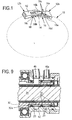
- the piston ring designated in its entirety with 10 consists of a hollow cylindrical ring body 12 rectangular or square cross-sectional shape, the at a circumferential point by a dividing line 14 is divided, which is Z-shaped by the ring body 12 extends.
- each one Due to the division of the ring body 12 with two Ring ends 12a, 12b, each one have tapered land that overlap each other and each in a next to the opposite bridge Border the arranged groove.
- the embodiment forming the ring end 12a has Web 16 a T-shaped cross-sectional shape with a Base web 16a, the z. B. is located radially inside, and from which a central web 16b z. B. radially outwards projects.
- the open at the end of the ring 12a Receiving grooves 16c are facing away from the ring end Circumferential direction essentially radial extending boundary surfaces 16f limited.
- the ring end 12b forming and z. B. radially outside arranged web 18 is axial by two Webs 18a having a spacing a from one another are formed, which is curved in the shape of the ring extend respectively associated receiving groove 16c.
- One is located radially inside of the webs 18a over the entire width b of the piston ring 10 extending receiving groove 18b, in which the base web 16a extends.
- a the receiving groove 18b in the Limiting surface 18c delimiting the circumferential direction extend in an axial plane E1 or with the Webs 18a form an obtuse angle W1, as shown in FIG. 3 shows.
- the end face 16g of the web 16a points from the boundary surface 18c one in the Distance c extending circumferential direction.
- the End face 16g can also be in an axial plane E2 extend or with the outer surface 16d Include an acute angle W2.
- the piston ring 10 has two piston rings 10 limiting, about the extent in the circumferential direction in Essentially parallel to each other Side surfaces 26 on.
- each other radially overlapping webs 16, 18 can open spaces 28a, 28b the radial height range h1, h2 of the existing between the ring ends 12a, 12b Gap distance c, f at these in the circumferential direction adjacent and tapering into the gap distance c, f be arranged.
- the free areas 28a, 28b are included offset about the amount of overlap in the circumferential direction in the end region of the webs 16a, 18a and opposite ends of the receiving grooves 16c, 18b are arranged adjacent.
- FIGS. 1 to 3 are only in the end regions of the adjacent to the gap distance f Side surfaces 26 free areas 28a available. At the 4 to 7 are also in the at the gap distance c adjacent end areas of Side surfaces 26 free areas 28b are provided.
- the respective free area 28 can be level E3 Side surface 26 either in the to the gap distance c, f directed circumferential directions (Fig. 1 to 3 and 5 right) or in the radial direction (FIG. 5 left) be convergent, e.g. B. with the Side surface 26 each an acute angle W3 lock in.
- the free areas 28a, 28b delimit in the installed state 3 each have a free space 28c which for associated ring end 12a, 12b towards or radially to diverged outside.
- the radial heights h1, h2 of the webs 16, 18 and receiving grooves 16c, 18b are in the Embodiments the same size.
- all open spaces can be used 28, 28a, 28b formed acute or rounded his.
- the piston ring 10 is made of known material such as elastically bendable metal, e.g. B. steel.
- a Piston ring 10 on a piston ring carrier 30 in the form a sleeve-shaped shaft mounted in one Gear housing 32 for a motor vehicle rotatable is mounted and surrounds a wheel drive shaft 34, which differ from a differential gear 36 to a Vehicle wheel, not shown, in particular one Front wheel, stretches.
- this is Differential gear 36 a torsional differential, with whose rotatably mounted base body 38 the Piston ring carrier 30 non-rotatably connected, for. B. screwed, is.
- the piston ring carrier 30 is by one or more Pivot bearing 40 and with little movement play in one non-rotatably arranged bushing 42, and he forms an axially effective barrier in the bushing 42 Annular gap 44 to prevent or minimize Pressure losses.
- Piston rings 10 there are at least two Piston rings 10 on either side of a radial Rotary inlet 46 for a hydraulic pressure fluid arranged, with a radial through channel 48 in the socket 42, the outside with a supply line 50th connected is.
- the through channel 48 opens inside an inner annular groove 52 in the socket 42, in the area thereof the piston ring carrier 30 a radially inward extending channel 54. From this channel 54 a continuation channel 56 branches off axially leads to a consumer.
- the rotary inlet 46 is used to the hydraulic pressure fluid to a not Actuator shown for a stepless adjustable gear.
- a second pressure fluid with a different, e.g. B. higher working pressure needed this can be done by a second Realize rotary insertion 46a in an axial Distance from the rotary inlet 46 is arranged and be identical or basically the same can, like the rotating inlet 46 and the associated Pressure medium supply, so that in this regard to the existing reference numerals and a repeated description can be omitted.
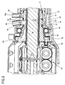
- the installation example according to FIG. 9 differs from 8 in that the piston rings 10 in Ring grooves 20 sit in a carrier sleeve 30a are arranged, which sits on the piston ring carrier 30 and is secured on it.
- the piston ring carrier 30 can a suitable ring recess for the carrier sleeve 30a exhibit. This configuration is u. a. out manufacturing reasons advantageous because the Ring grooves 20 on a small additional component can be trained more easily than on the larger one Piston ring carrier 30.
- the invention is suitable Design of the piston rings 10 particularly well. in this connection it must be taken into account that the at least one Piston ring 10 axially acted upon by the fluid pressure and therefore on the pressurization opposite side a considerable Wear stress between the piston ring 10 and the side wall of the annular groove 20 supporting it takes place. In this case it is enough for one Reduction of the piston ring's susceptibility to wear 10 out, this on the pressurization Train away side according to the invention.
- the piston ring 10 also in these cases to train that it is independent of its installation, it is advantageous to the piston ring 10 on its two To form side surfaces 26 according to the invention.
Landscapes
- Engineering & Computer Science (AREA)
- General Engineering & Computer Science (AREA)
- Mechanical Engineering (AREA)
- Pistons, Piston Rings, And Cylinders (AREA)
Abstract
Description
- Fig. 1
- eine schematische perspektivische Darstellung eines durch eine Teilungsfuge geteilten Kolbenrings mit einem Verschluss für die Ringenden nach der Erfindung;
- Fig. 2
- eine Draufsicht auf den Verschluss von Fig. 1 in vergrößerter Darstellung;
- Fig. 3
- eine Seitenansicht des Verschlusses von Fig. 1;
- Fig. 4
- eine Ansicht von innen des Verschlusses von Fig. 3 in abgewandelter Ausgestaltung;
- Fig. 5
- eine Ansicht von innen des Verschlusses von Fig. 4 in weiter abgewandelter Ausgestaltung;
- Fig. 6
- eine Seitenansicht eines abgewandelten Verschlusses nach der Erfindung;
- Fig. 7
- eine Ansicht von innen des Verschlusses von Fig. 6;
- Fig. 8
- einen Teilquerschnitt eines Kraftfahrzeuggetriebes mit mehreren erfindungsgemäßen Kolbenringen auf einem Kolben; und
- Fig. 9
- einen Teilquerschnitt des Getriebes von Fig. 8 in abgewandelter Ausgestaltung.
- 10
- Kolbenring
- 12
- Ringkörper
- 12a
- Ringende
- 12b
- Ringende
- 14
- Teilungsfuge
- 16
- Steg
- 16a
- Basissteg
- 16b
- Mittelsteg
- 16c
- Aufnahmenut
- 16d
- Außenfläche
- 16e
- Seitenfläche
- 16f
- Begrenzungsfläche
- 16g
- Stirnfläche
- 18
- Steg
- 18a
- Steg
- 18b
- Aufnahmenut
- 18c
- Begrenzungsfläche
- 18d
- Aufnahmenut
- 20
- Ringnut
- 22
- Kolben
- 24
- Buchse
- 26
- Seitenfläche
- 28
- Freifläche
- 28a
- Freifläche
- 28b
- Freifläche
- 28c
- Freiraum
- 30
- Kolbenringträger
- 30a
- Trägerhülse
- 32
- Getriebegehäuse
- 34
- Radantriebswelle
- 36
- Differentialgetriebe
- 38
- Basiskörper
- 40
- Drehlager
- 42
- Buchse
- 44
- Ringspalt
- 46
- Dreheinführung
- 46a
- Dreheinführung
- 48
- Durchgangskanal
- 50
- Zuführungsleitungen
- 52
- Innenringnut
- 54
- Kanal
- 56
- Weiterführungskanal
- a
- axialer Abstand
- b
- Breite
- c
- Spaltabstand
- d
- Breite
- e
- Abstand
- f
- Abstand
- h1
- Höhenbereich
- h2
- Höhenbereich
- D1
- Innendurchmesser
- D2
- Innendurchmesser
- E1
- Axialebene
- E2
- Axialebene
- E3
- Ebene der Seitenfläche
- W1
- Winkel
- W2
- Winkel
- W3
- Winkel
- W4
- Winkel
Claims (9)
- Kolbenring (10) mit zwei den Kolbenring (10) seitlich begrenzenden, über die Umfangserstreckung im Wesentlichen parallel zueinander verlaufenden Seitenflächen (26) mit zwei Ringenden (12a, 12b) und mit einer die zwei Ringenden (12a, 12b) bildenden Teilungsfuge (14), die durch verjüngte und sich überlappende Stege (16a, 18a) im Bereich der Ringenden (12a, 12b) überlappt ist, dadurch gekennzeichnet, dass auf einer oder auf beiden Seiten des Kolbenrings (10) bei einem Ringende (12a, 12b) oder bei beiden Ringenden (12a, 12b) jeweils eine vertiefte Freifläche (28) vorgesehen ist, die sich von der zugehörigen Seitenfläche (26) in Richtung auf das zugehörige Ringende (12a, 12b) erstreckt und am Ringende (12a, 12b) ausläuft.
- Kolbenring nach Anspruch 1, dadurch gekennzeichnet, dass die Freifläche (28) auch zu dem Außenumfang des Kolbenrings (10) ausläuft.
- Kolbenring nach Anspruch 1 oder 2, dadurch gekennzeichnet, dass die Freifläche (28) sich bezüglich der Ebene der Seitenfläche (26) divergent zum Ringende (12a, 12b) und/oder zum Außenumfang des Kolbenrings (10) erstreckt.
- Kolbenring nach Anspruch 3, dadurch gekennzeichnet, dass die Freifläche (28) mit der Ebene (E3) der Seitenfläche (26) einen spitzen Winkel (W3, W4) einschließt, der vorzugsweise etwa 5° bis 30° beträgt.
- Kolbenring nach Anspruch 3, dadurch gekennzeichnet, dass die Freifläche (28) sich konvex gerundet erstreckt.
- Kolbenring nach einem der vorherigen Ansprüche, dadurch gekennzeichnet, dass die Stege (16, 18) einander in radialer Richtung und/oder axialer Richtung überlappen.
- Kolbenring nach Anspruch 6, dadurch gekennzeichnet, dass die Stege (16, 18) einander in radialer Richtung überlappen und einer der beiden Stege (16, 18) einen Mittelsteg (16a) aufweist, der in eine Aufnahmenut (18d) im anderen Steg (18) einfasst.
- Kolbenring nach Anspruch 6 oder 7, dadurch gekennzeichnet, dass zwischen den Stirnflächen (16f, 16g, 18f) und den gegenüberliegenden Begrenzungsflächen (16f, 18c) der Aufnahmenuten (16c, 18d) im montierten Zustand jeweils ein Spaltabstand (c, f) angeordnet ist.
- Kolbenring nach einem der vorherigen Ansprüche, dadurch gekennzeichnet, dass er bezüglich einer radialen Mittelebene spiegelsymmetrisch ausgebildet ist.
Applications Claiming Priority (2)
| Application Number | Priority Date | Filing Date | Title |
|---|---|---|---|
| DE2003104565 DE10304565A1 (de) | 2003-02-05 | 2003-02-05 | Kolbenring |
| DE10304565 | 2003-02-05 |
Publications (2)
| Publication Number | Publication Date |
|---|---|
| EP1445518A1 true EP1445518A1 (de) | 2004-08-11 |
| EP1445518B1 EP1445518B1 (de) | 2007-03-07 |
Family
ID=32603152
Family Applications (1)
| Application Number | Title | Priority Date | Filing Date |
|---|---|---|---|
| EP20030027235 Expired - Lifetime EP1445518B1 (de) | 2003-02-05 | 2003-11-28 | Kolbenring |
Country Status (2)
| Country | Link |
|---|---|
| EP (1) | EP1445518B1 (de) |
| DE (2) | DE10304565A1 (de) |
Cited By (3)
| Publication number | Priority date | Publication date | Assignee | Title |
|---|---|---|---|---|
| EP2484868A3 (de) * | 2011-02-04 | 2013-12-25 | MTU Aero Engines GmbH | Dämpfungsring |
| WO2018138574A1 (en) * | 2017-01-10 | 2018-08-02 | Saint-Gobain Performance Plastics L+S GMBH | Seal rings and methods for making them |
| US10690248B2 (en) | 2017-01-10 | 2020-06-23 | Saint-Gobain Performance Plastics L+S GMBH | Injection molded seal rings and methods for making them |
Citations (4)
| Publication number | Priority date | Publication date | Assignee | Title |
|---|---|---|---|---|
| US1343828A (en) * | 1919-02-18 | 1920-06-15 | Robert M Jordan | Piston-ring |
| US1350849A (en) * | 1920-08-24 | Adolf stern | ||
| FR1118722A (fr) * | 1955-02-07 | 1956-06-11 | Segment à coupe étanche | |
| DE3612454A1 (de) * | 1986-04-14 | 1987-10-15 | Friedhelm Stecher | Kolbenringe |
Family Cites Families (7)
| Publication number | Priority date | Publication date | Assignee | Title |
|---|---|---|---|---|
| US1635407A (en) * | 1922-02-27 | 1927-07-12 | Grover Ray | Piston ring |
| US1763127A (en) * | 1926-05-17 | 1930-06-10 | Beer Georg | Piston ring |
| US2569777A (en) * | 1946-10-12 | 1951-10-02 | Hastings Mfg Co | Piston ring |
| US2768865A (en) * | 1952-06-07 | 1956-10-30 | Safety Seal Piston Ring Compan | Piston or packing rings |
| DE1885367U (de) * | 1963-10-28 | 1964-01-02 | Paul Stantic | Kolbenring. |
| AT281504B (de) * | 1967-11-10 | 1970-05-25 | Bayerische Motoren Werke Ag | Kolben mit Kolbenringen für Brennkraftmaschinen |
| US3784215A (en) * | 1971-11-12 | 1974-01-08 | Koppers Co Inc | Interlocking joint for sealing rings |
-
2003
- 2003-02-05 DE DE2003104565 patent/DE10304565A1/de not_active Withdrawn
- 2003-11-28 DE DE50306738T patent/DE50306738D1/de not_active Expired - Lifetime
- 2003-11-28 EP EP20030027235 patent/EP1445518B1/de not_active Expired - Lifetime
Patent Citations (4)
| Publication number | Priority date | Publication date | Assignee | Title |
|---|---|---|---|---|
| US1350849A (en) * | 1920-08-24 | Adolf stern | ||
| US1343828A (en) * | 1919-02-18 | 1920-06-15 | Robert M Jordan | Piston-ring |
| FR1118722A (fr) * | 1955-02-07 | 1956-06-11 | Segment à coupe étanche | |
| DE3612454A1 (de) * | 1986-04-14 | 1987-10-15 | Friedhelm Stecher | Kolbenringe |
Cited By (6)
| Publication number | Priority date | Publication date | Assignee | Title |
|---|---|---|---|---|
| EP2484868A3 (de) * | 2011-02-04 | 2013-12-25 | MTU Aero Engines GmbH | Dämpfungsring |
| WO2018138574A1 (en) * | 2017-01-10 | 2018-08-02 | Saint-Gobain Performance Plastics L+S GMBH | Seal rings and methods for making them |
| CN110249164A (zh) * | 2017-01-10 | 2019-09-17 | 圣戈班高性能塑料有限公司 | 密封环及其制备方法 |
| US10648567B2 (en) | 2017-01-10 | 2020-05-12 | Saint-Gobain Performance Plastics L+S GMBH | Seal rings and methods for making them |
| US10690248B2 (en) | 2017-01-10 | 2020-06-23 | Saint-Gobain Performance Plastics L+S GMBH | Injection molded seal rings and methods for making them |
| CN110249164B (zh) * | 2017-01-10 | 2021-03-09 | 圣戈班性能塑料L+S 有限公司 | 密封环及其制备方法 |
Also Published As
| Publication number | Publication date |
|---|---|
| DE10304565A1 (de) | 2004-08-19 |
| EP1445518B1 (de) | 2007-03-07 |
| DE50306738D1 (de) | 2007-04-19 |
Similar Documents
| Publication | Publication Date | Title |
|---|---|---|
| DE102017127876A1 (de) | Planetengetriebe und Gleitlagerstift für ein Planetengetriebe | |
| EP2221510B1 (de) | Planetenrad mit einem eine axiale Nut aufweisenden Lagerbolzen | |
| DE4139611A1 (de) | Getriebe mit einer verdraengerpumpe | |
| DE69916711T2 (de) | Hydromotor in Kompaktbauweise | |
| DE112005001719T5 (de) | Kugelförmiges Gleitlagersystem | |
| DE2835572C3 (de) | Anordnung zur Zuführung von Drucköl | |
| DE112006001875B4 (de) | Fahrzeugautomatikgetriebe | |
| DE10203265A1 (de) | Anlaufscheibe eines Planetengetriebes | |
| DE19622446C1 (de) | Zapfenkreuzgarnitur für Kreuzgelenke | |
| DE202013102506U1 (de) | Innenzahnradmaschine mit Schrägbohrungen zur Verbindung hydrostatischer Lager für ein Hohlrad mit einem Druck-Hauptkanal | |
| DE29506365U1 (de) | Raupenfahrwerk, insbesondere für Kleinbagger | |
| DE102017127874A1 (de) | Planetengetriebe und Planetenrad für ein Planetengetriebe | |
| EP1302679B1 (de) | Lagerhülse für ein Kurbelwellendrucklager | |
| DE19815134B4 (de) | Spindelkopf für Werkzeugmaschinen | |
| DE3342131C2 (de) | ||
| EP0754839B1 (de) | Stellvorrichtung zur relativen Winkelverstellung einer angetriebenen Welle, insbesondere Nockenwelle einer Brennkraftmaschine | |
| EP1445518B1 (de) | Kolbenring | |
| DE202013102079U1 (de) | Zahnradmaschine mit formschlüssiger Axialsicherung einer Lagerbuchse einer Wellenlagerung | |
| DE10053580A1 (de) | Handwerkzeugmaschine mit einem in einer Werkzeughalterung angeordneten Dichtungsring | |
| EP0836006A2 (de) | Kolbenpumpe | |
| DE102007017652A1 (de) | Rotationskolbenmaschine | |
| DE10322501A1 (de) | Drehkolbenpumpe | |
| DE102017127866A1 (de) | Planetengetriebe und Gleitlagerstift für ein Planetengetriebe | |
| EP4430327A1 (de) | Anordnung mit zwei bauteilen und einem ölübertragungsring | |
| DE19829925A1 (de) | Zahnräderwechselgetriebe |
Legal Events
| Date | Code | Title | Description |
|---|---|---|---|
| PUAI | Public reference made under article 153(3) epc to a published international application that has entered the european phase |
Free format text: ORIGINAL CODE: 0009012 |
|
| AK | Designated contracting states |
Kind code of ref document: A1 Designated state(s): AT BE BG CH CY CZ DE DK EE ES FI FR GB GR HU IE IT LI LU MC NL PT RO SE SI SK TR |
|
| AX | Request for extension of the european patent |
Extension state: AL LT LV MK |
|
| 17P | Request for examination filed |
Effective date: 20040702 |
|
| 17Q | First examination report despatched |
Effective date: 20041027 |
|
| AKX | Designation fees paid |
Designated state(s): DE FR GB |
|
| RBV | Designated contracting states (corrected) |
Designated state(s): DE FR GB |
|
| GRAP | Despatch of communication of intention to grant a patent |
Free format text: ORIGINAL CODE: EPIDOSNIGR1 |
|
| GRAS | Grant fee paid |
Free format text: ORIGINAL CODE: EPIDOSNIGR3 |
|
| GRAA | (expected) grant |
Free format text: ORIGINAL CODE: 0009210 |
|
| AK | Designated contracting states |
Kind code of ref document: B1 Designated state(s): DE FR GB |
|
| REG | Reference to a national code |
Ref country code: GB Ref legal event code: FG4D Free format text: NOT ENGLISH |
|
| REF | Corresponds to: |
Ref document number: 50306738 Country of ref document: DE Date of ref document: 20070419 Kind code of ref document: P |
|
| GBT | Gb: translation of ep patent filed (gb section 77(6)(a)/1977) |
Effective date: 20070423 |
|
| ET | Fr: translation filed | ||
| PLBE | No opposition filed within time limit |
Free format text: ORIGINAL CODE: 0009261 |
|
| STAA | Information on the status of an ep patent application or granted ep patent |
Free format text: STATUS: NO OPPOSITION FILED WITHIN TIME LIMIT |
|
| 26N | No opposition filed |
Effective date: 20071210 |
|
| PGFP | Annual fee paid to national office [announced via postgrant information from national office to epo] |
Ref country code: DE Payment date: 20141130 Year of fee payment: 12 |
|
| REG | Reference to a national code |
Ref country code: FR Ref legal event code: PLFP Year of fee payment: 13 |
|
| PGFP | Annual fee paid to national office [announced via postgrant information from national office to epo] |
Ref country code: GB Payment date: 20151123 Year of fee payment: 13 |
|
| PGFP | Annual fee paid to national office [announced via postgrant information from national office to epo] |
Ref country code: FR Payment date: 20151123 Year of fee payment: 13 |
|
| REG | Reference to a national code |
Ref country code: DE Ref legal event code: R119 Ref document number: 50306738 Country of ref document: DE |
|
| PG25 | Lapsed in a contracting state [announced via postgrant information from national office to epo] |
Ref country code: DE Free format text: LAPSE BECAUSE OF NON-PAYMENT OF DUE FEES Effective date: 20160601 |
|
| GBPC | Gb: european patent ceased through non-payment of renewal fee |
Effective date: 20161128 |
|
| REG | Reference to a national code |
Ref country code: FR Ref legal event code: ST Effective date: 20170731 |
|
| PG25 | Lapsed in a contracting state [announced via postgrant information from national office to epo] |
Ref country code: FR Free format text: LAPSE BECAUSE OF NON-PAYMENT OF DUE FEES Effective date: 20161130 |
|
| PG25 | Lapsed in a contracting state [announced via postgrant information from national office to epo] |
Ref country code: GB Free format text: LAPSE BECAUSE OF NON-PAYMENT OF DUE FEES Effective date: 20161128 |