EP1445231A2 - Méthode et dispositif de détection de surcharge sur des grues portiques - Google Patents
Méthode et dispositif de détection de surcharge sur des grues portiques Download PDFInfo
- Publication number
- EP1445231A2 EP1445231A2 EP04002108A EP04002108A EP1445231A2 EP 1445231 A2 EP1445231 A2 EP 1445231A2 EP 04002108 A EP04002108 A EP 04002108A EP 04002108 A EP04002108 A EP 04002108A EP 1445231 A2 EP1445231 A2 EP 1445231A2
- Authority
- EP
- European Patent Office
- Prior art keywords
- load
- trolley
- crane
- load cells
- cells
- Prior art date
- Legal status (The legal status is an assumption and is not a legal conclusion. Google has not performed a legal analysis and makes no representation as to the accuracy of the status listed.)
- Withdrawn
Links
Images

Classifications
-
- B—PERFORMING OPERATIONS; TRANSPORTING
- B66—HOISTING; LIFTING; HAULING
- B66C—CRANES; LOAD-ENGAGING ELEMENTS OR DEVICES FOR CRANES, CAPSTANS, WINCHES, OR TACKLES
- B66C15/00—Safety gear
Definitions
- the invention relates to a method and a device for incorrect load detection on a gantry crane, preferably for a pouring or charging crane in the Metallurgy.
- Lifting devices have been developed for lifting loads in rooms that are difficult to access or at risk. Load handling is problematic in cases when the crane operator's visibility is restricted during the lifting process. Such situations usually require instruction from the crane operator in order to rule out dangerous moments when lifting the load and to ensure safe transport. Instruction during the slinging process is usually always associated with the use of an additional worker, which has an adverse effect on the effectiveness of the transport. Particularly in metallurgy, where charging vessels and ladles of various designs are used to transport molten metals, well-functioning, self-supporting lifting devices are necessary to ensure smooth transport of the molten metal between the individual production units. Despite the presence of such load suspension devices, a residual risk cannot be excluded. Incorrect load pick-up can, however, lead to a significant accident with several days of production downtime. In metallurgical plants in particular, the damage can be considerable if a pan with melt liquid is caught on one side and the melt liquid escapes from the vessel.
- the load suspension device is equipped with load suspension elements, which are individually resiliently arranged on the supporting structure of the load suspension device.
- the load suspension devices are attached to bolts which are guided in the vertical direction through elongated holes in the web plates.
- the bolts are spring-loaded and each have a switching flag, which is coupled to a pulse generator. These pulse generators trigger a signal if not all pulse generators emit the same signal or the number of pulse generators does not match the number of signals emitted by the pulse generators.
- Such a solution has the defect that the load suspension device must be designed accordingly in order to install the pulse generator. Furthermore, the arrangement of the sensors in the immediate area of the load, particularly when used in metallurgy, is problematic, since such a solution is extremely susceptible to failure due to the existing loads caused by heat and dust.
- the object of the invention is a method and a device for To develop gantry cranes with under difficult external conditions, such as B. heat and dust, a safe control of Load pickup can be guaranteed and thus the safety when Striking the load and transporting it increases downtime as well Production facilities due to damage from damaged loads be avoided.
- the object is achieved by a method according to claim 1 solved.
- a device for implementing the method is in the claims 2 and 3 described.
- the exemplary embodiment relates to the detection of incorrect loads on a charging crane in a steel mill.
- Such cranes essentially consist of a trolley 2 on which two cable drums 1 for receiving the supporting cables are arranged, to which a crossbar 8 is attached with two load-bearing hooks 9 fastened to it on both sides.
- the trolley 2 consists of a support frame with four wheels 4 arranged at the corner points of the support frame, which can be moved on a carrier A, 7 in FIG. 1, or on a carrier D, marked 6 in FIG. 1.
- the supporting frame of the trolley 2 is supported at its four end points on load cells 3a and 3b, the load cells 3a and 3b being assigned to a load-carrying side.
- load cells 3a 1-4 and 3b 1-4 are located on each of the two load-carrying sides, which are arranged on both sides of an impeller 4 of the trolley 2.
- Crane impellers 5 on the supports A and D enable the trolley 2 to be moved in the longitudinal direction to the charging hall.
- An auxiliary stroke not shown in the drawings, serves to generate the necessary tilting movement during charging.
- the measured value acquisition is initially carried out separately for both sides of the trolley 2 in order to record a possible asymmetrical load on the load cells during load acceptance.
- An asymmetrical load on the load cells occurs when a crane hook 9 is not or not correctly inserted in the support bracket / ladle hanger. The loader then picks up the load on one side.
- the charging pan can be tipped over by an asymmetrical load bearing, which creates a high risk of accidents and considerable malfunctions.
- the invention is also intended to rule out the case where both crane hook tips are located under the two support brackets / pan hangers of a charging pan and thus, although the load is evenly distributed, there is a high risk of the support brackets / pan hangers sliding off the crane hook tips.
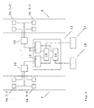
- the four load cells 3a 1-4 or 3b 1-4 arranged on the two sides of the trolley 2 are divided into two separate measuring circuits.
- the load cells 3a 1-4 of the load side A are connected to a switch box 10 via measuring lines and the load cells 3b 1-4 of the load side D are connected to a switch box 11.
- a measurement value equivalent to the respective side A or D is formed from the four measurement values of the load cells.
- the two switch boxes 10 and 11 are connected to an evaluation unit 12 for further processing of the measurement signals.
- the evaluation unit 12 consists of a measuring circuit A marked with reference number 13 for determining the weight value of the load side A and a measuring circuit D marked with reference number 14 for determining the weight value of the load side D.
- a differentiator 15 and a summer 16 are arranged in the evaluation unit 12, which are connected in parallel to the two measuring circuits A and D and are connected to them via corresponding cables.
- the load pick-up is a dynamic process, i.e. the weight value changes with the load pick-up depending on the time. Based on this, the change in the weight value of the load-bearing side A is compared with the change in the weight value of the load-bearing side D by the differentiator at the time of the load bearing. The measured value determined from the comparison of the two measurement signals present on the load sides A and D is shown in a subordinate display 17. If the difference exceeds a previously defined amount, there is an incorrect load detection.
- this can also trigger an acoustic signal to warn the personnel.
- the hazard detection of load pick-up on both sides of the crane hook tips was solved by raising one of the two crane hook tips. As a result of this increase, which can be approximately 100 mm in the case of a crane of this type, an unequal change in the weight value when the load is lifted is also indicated when the load is lifted on both sides via the crane hook tips. Safe transport can only take place when the two crane hooks 9 are correctly seated on the support brackets / pan hangers of the charging pan, which is characterized by the same height of the two support points. With the application of the invention, the risk of incorrect load pick-up can be excluded and safe transport can be ensured.
- the summer 16 forms the two applied measurement signals on the load sides A and D by totaling a total that is the total weight which represents the charging pan hanging on the two crane hooks 9.
Landscapes
- Engineering & Computer Science (AREA)
- Mechanical Engineering (AREA)
- Control And Safety Of Cranes (AREA)
Applications Claiming Priority (2)
| Application Number | Priority Date | Filing Date | Title |
|---|---|---|---|
| DE10304951 | 2003-02-06 | ||
| DE2003104951 DE10304951A1 (de) | 2003-02-06 | 2003-02-06 | Verfahren und Einrichtung zur Fehllasterkennung an Brückenkranen |
Publications (2)
| Publication Number | Publication Date |
|---|---|
| EP1445231A2 true EP1445231A2 (fr) | 2004-08-11 |
| EP1445231A3 EP1445231A3 (fr) | 2004-12-22 |
Family
ID=32603188
Family Applications (1)
| Application Number | Title | Priority Date | Filing Date |
|---|---|---|---|
| EP04002108A Withdrawn EP1445231A3 (fr) | 2003-02-06 | 2004-01-31 | Méthode et dispositif de détection de surcharge sur des grues portiques |
Country Status (2)
| Country | Link |
|---|---|
| EP (1) | EP1445231A3 (fr) |
| DE (1) | DE10304951A1 (fr) |
Cited By (2)
| Publication number | Priority date | Publication date | Assignee | Title |
|---|---|---|---|---|
| CN102785999A (zh) * | 2011-05-16 | 2012-11-21 | 江苏申大衡器有限公司 | 无线数传智能天车称重系统 |
| EP2313336B1 (fr) * | 2008-08-20 | 2015-04-01 | Firma Physik-Instrumente Dr. Bernd Brosa GmbH | Reconnaissance précoce d'une surcharge, pour un équipement de levage |
Families Citing this family (3)
| Publication number | Priority date | Publication date | Assignee | Title |
|---|---|---|---|---|
| DE102012015095A1 (de) | 2012-08-01 | 2014-02-06 | Vdeh-Betriebsforschungsinstitut Gmbh | Haken eines Krans mit einer Winkelmesseinheit und Verfahren zur Fehllasterkennung mit Automatisierungskonzept |
| DE102013017803B4 (de) | 2013-10-28 | 2017-01-05 | Vdeh-Betriebsforschungsinstitut Gmbh | "Fehllageerkennungssystem, Hebezeug, Kran und Verfahren zur Fehllageerkennung" |
| CN108002231A (zh) * | 2017-11-30 | 2018-05-08 | 无锡市汇鼎金属制管有限公司 | 一种起重机用称重装置 |
Citations (2)
| Publication number | Priority date | Publication date | Assignee | Title |
|---|---|---|---|---|
| DE2527411A1 (de) * | 1975-06-20 | 1977-01-13 | Krupp Gmbh | Chargierkran |
| EP0595222A1 (fr) * | 1992-10-24 | 1994-05-04 | Ralf Koschinski | Dispositif de levage de charges, en particulier pour des conteneurs |
-
2003
- 2003-02-06 DE DE2003104951 patent/DE10304951A1/de not_active Withdrawn
-
2004
- 2004-01-31 EP EP04002108A patent/EP1445231A3/fr not_active Withdrawn
Patent Citations (2)
| Publication number | Priority date | Publication date | Assignee | Title |
|---|---|---|---|---|
| DE2527411A1 (de) * | 1975-06-20 | 1977-01-13 | Krupp Gmbh | Chargierkran |
| EP0595222A1 (fr) * | 1992-10-24 | 1994-05-04 | Ralf Koschinski | Dispositif de levage de charges, en particulier pour des conteneurs |
Cited By (3)
| Publication number | Priority date | Publication date | Assignee | Title |
|---|---|---|---|---|
| EP2313336B1 (fr) * | 2008-08-20 | 2015-04-01 | Firma Physik-Instrumente Dr. Bernd Brosa GmbH | Reconnaissance précoce d'une surcharge, pour un équipement de levage |
| KR101625248B1 (ko) | 2008-08-20 | 2016-05-27 | 퍼르마 피직-인스투르먼트 닥터 번드 브로사 게엠베하 | 화물 승강 장치용 조기 과부하 검출 방법 |
| CN102785999A (zh) * | 2011-05-16 | 2012-11-21 | 江苏申大衡器有限公司 | 无线数传智能天车称重系统 |
Also Published As
| Publication number | Publication date |
|---|---|
| EP1445231A3 (fr) | 2004-12-22 |
| DE10304951A1 (de) | 2004-08-26 |
Similar Documents
| Publication | Publication Date | Title |
|---|---|---|
| EP1453754B1 (fr) | Dispositif et procede de controle de charge sans contact sur des installations de grutage | |
| EP2799386B1 (fr) | Dispositif et procédé de détermination et de surveillance d'un contre-poids équipé sur une grue | |
| DE69110301T2 (de) | Hebestrangverbindungsstücke mit maximalarbeitslastmarkierungen. | |
| DE3606363A1 (de) | Einrichtung zur bestimmung der lage eines fahrzeugs relativ zu einer container-hebevorrichtung | |
| DE3019385A1 (de) | Kran mit datenverarbeitungsanlage | |
| EP2636634A1 (fr) | Grue et procédé de commande de grue | |
| DE10233875B4 (de) | Krananlage, insbesondere Containerkran | |
| DE112020000738T5 (de) | Träger für eine Hebevorrichtung, damit versehene Hebevorrichtung und dazugehörige Arbeitsweise | |
| EP2313336B1 (fr) | Reconnaissance précoce d'une surcharge, pour un équipement de levage | |
| EP1445231A2 (fr) | Méthode et dispositif de détection de surcharge sur des grues portiques | |
| DE4005066A1 (de) | Containerbruecke | |
| DE19725315C2 (de) | Kran, insbesondere Hüttenwerkskran | |
| DE202006017730U1 (de) | Mobilkran | |
| DE102009060638A1 (de) | Werkstatteinrichtung eines Hütten- oder Walzwerks | |
| AT508795B1 (de) | Verfahren und vorrichtung zum auswechseln einer rollenbatterie | |
| DE102006035732B4 (de) | Entladebrücke zum Be- und/oder Entladen des Laderaumes eines Schiffes, vzw. mit Containern | |
| DE202017003239U1 (de) | Vorrichtung zum sicheren und schnellen Transfer neuer Glasplatten von der Fertigungslinie zu einem Transportfahrzeug | |
| DE102017126182B4 (de) | Kraftmessvorrichtung mit Dynamikkompensation | |
| DE102019102828A1 (de) | Verfahren und Vorrichtung zur Verhinderung von Schlaffseil | |
| DE102013017803B4 (de) | "Fehllageerkennungssystem, Hebezeug, Kran und Verfahren zur Fehllageerkennung" | |
| DE102012010248A1 (de) | Lastumschlag-Fahrzeug und Verfahren zur Bestimmung einer Gewichtsverteilung einer Last an einem Lastumschlag-Fahrzeug | |
| DE102015214945A1 (de) | Wiegevorrichtung und Verfahren zum Betreiben einer solchen Wiegevorrichtung | |
| DE4012381C2 (de) | Verwendung eines Laufkrans zum Wenden von Lasten und Verfahren zum Wenden der Last | |
| EP0595222B1 (fr) | Dispositif de levage de charges, en particulier pour des conteneurs | |
| DE102014108016A1 (de) | Verfahren zum Be- und Entladen eines Routenzugs |
Legal Events
| Date | Code | Title | Description |
|---|---|---|---|
| PUAI | Public reference made under article 153(3) epc to a published international application that has entered the european phase |
Free format text: ORIGINAL CODE: 0009012 |
|
| AK | Designated contracting states |
Kind code of ref document: A2 Designated state(s): AT BE BG CH CY CZ DE DK EE ES FI FR GB GR HU IE IT LI LU MC NL PT RO SE SI SK TR |
|
| AX | Request for extension of the european patent |
Extension state: AL LT LV MK |
|
| RIN1 | Information on inventor provided before grant (corrected) |
Inventor name: SCHIRMER, MARTIN Inventor name: FEUERSTEIN, RALF Inventor name: SCHALLER, KLAUS |
|
| PUAL | Search report despatched |
Free format text: ORIGINAL CODE: 0009013 |
|
| RIC1 | Information provided on ipc code assigned before grant |
Ipc: 7B 66C 17/10 B Ipc: 7B 66C 19/00 B Ipc: 7B 66C 15/06 B Ipc: 7B 66C 13/16 A |
|
| AK | Designated contracting states |
Kind code of ref document: A3 Designated state(s): AT BE BG CH CY CZ DE DK EE ES FI FR GB GR HU IE IT LI LU MC NL PT RO SE SI SK TR |
|
| AX | Request for extension of the european patent |
Extension state: AL LT LV MK |
|
| AKX | Designation fees paid | ||
| REG | Reference to a national code |
Ref country code: DE Ref legal event code: 8566 |
|
| STAA | Information on the status of an ep patent application or granted ep patent |
Free format text: STATUS: THE APPLICATION IS DEEMED TO BE WITHDRAWN |
|
| 18D | Application deemed to be withdrawn |
Effective date: 20050623 |