EP1444893A1 - Landwirtschaftliche Feldspritze - Google Patents
Landwirtschaftliche Feldspritze Download PDFInfo
- Publication number
- EP1444893A1 EP1444893A1 EP04001277A EP04001277A EP1444893A1 EP 1444893 A1 EP1444893 A1 EP 1444893A1 EP 04001277 A EP04001277 A EP 04001277A EP 04001277 A EP04001277 A EP 04001277A EP 1444893 A1 EP1444893 A1 EP 1444893A1
- Authority
- EP
- European Patent Office
- Prior art keywords
- valves
- cover
- shut
- valve
- valve shaft
- Prior art date
- Legal status (The legal status is an assumption and is not a legal conclusion. Google has not performed a legal analysis and makes no representation as to the accuracy of the status listed.)
- Granted
Links
Images




Classifications
-
- F—MECHANICAL ENGINEERING; LIGHTING; HEATING; WEAPONS; BLASTING
- F16—ENGINEERING ELEMENTS AND UNITS; GENERAL MEASURES FOR PRODUCING AND MAINTAINING EFFECTIVE FUNCTIONING OF MACHINES OR INSTALLATIONS; THERMAL INSULATION IN GENERAL
- F16K—VALVES; TAPS; COCKS; ACTUATING-FLOATS; DEVICES FOR VENTING OR AERATING
- F16K35/00—Means to prevent accidental or unauthorised actuation
- F16K35/14—Means to prevent accidental or unauthorised actuation interlocking two or more valves
-
- A—HUMAN NECESSITIES
- A01—AGRICULTURE; FORESTRY; ANIMAL HUSBANDRY; HUNTING; TRAPPING; FISHING
- A01M—CATCHING, TRAPPING OR SCARING OF ANIMALS; APPARATUS FOR THE DESTRUCTION OF NOXIOUS ANIMALS OR NOXIOUS PLANTS
- A01M7/00—Special adaptations or arrangements of liquid-spraying apparatus for purposes covered by this subclass
- A01M7/0089—Regulating or controlling systems
-
- F—MECHANICAL ENGINEERING; LIGHTING; HEATING; WEAPONS; BLASTING
- F16—ENGINEERING ELEMENTS AND UNITS; GENERAL MEASURES FOR PRODUCING AND MAINTAINING EFFECTIVE FUNCTIONING OF MACHINES OR INSTALLATIONS; THERMAL INSULATION IN GENERAL
- F16K—VALVES; TAPS; COCKS; ACTUATING-FLOATS; DEVICES FOR VENTING OR AERATING
- F16K27/00—Construction of housing; Use of materials therefor
- F16K27/12—Covers for housings
Definitions
- the invention relates to an agricultural field sprayer according to the preamble of claim 1.
- Such sprayers are in agriculture in various design in use.
- Such agricultural sprayers have a Variety of control valves on.
- control valves on.
- the invention is based on the object with simple Means possible operating errors and incorrect settings at least on the pressure side of the field spray lines avoid.
- the breakthrough has such a size on that only the actuators / the Actuating a branch line through the opening is operable by hand.
- a cover wall connected to the frame is provided is that behind the cover wall the valves and Branch lines are arranged, that the cover wall has at least one section through which the Valve shaft of the distribution valve protrudes, that the Operating lever is arranged in front of the cover wall.
- the branch line 9 leads via a branch to the container filling line 9 'and to a further filling line 9 " for further containers .
- These two lines 9' and 9" are arranged shutoff valves 12 which are arranged in the vicinity of the distributor valve 5 and have manual actuation elements 11.
- the branch line 10 leads from the distribution valve 5 via a branch to the inner cleaning line 10 'of the liquid container 1 and the outer cleaning line 10 ".
- These two cleaning lines 10' and 10" are in turn assigned shut-off valves 12 having hand-operated elements 11 arranged in the vicinity of the distributor valve 5.
- the distribution valve 5 has the manual operating lever 18 and a cover plate 19 with opening 20, not in Fig. 1, but in Fig. 3 to 9, on.
- the arrangement and Function of this cover 19 with breakthrough 20 is explained in more detail below.
- the actuating elements 11 of the shut-off valve 12 are, as Fig. 2 shows, on a to the valve shaft 22 of the Distributor valve 5 beaten circular arc 23 and within arranged covered by the cover 19 area.
- the cover 19 is rotatably connected to the valve shaft 22 of the Distributed valve 5 connected.
- On the valve shaft 22 is rotatably arranged the manual operating lever 18.
- In the Cover 19 is an opening 20, located in the Distance that is about the middle distance of the Actuators 11 of the shut-off valves 12 'of the Valve shaft 22 corresponds, is located by the valve shaft 22, arranged.
- the aperture 20 has such a size, that only the actuators 11 and the Actuator 11 a branch line 7,8,9,10 by the Breakthrough 20 is actuated by hand, as shown in FIGS. 3 to 9 demonstrate.
- the manual operation lever 18 of the distribution valve 5 or the Cover 19 act with Einstellmark isten 24 and / or Designations 25 together to provide for the operator Adjustment of the distributor valve 5 for the respective Function type to make recognizable and readable.
- these adjustment marks 24 and Setting designations 25 in the area of the shut-off valves 12 formed by means of the labeling representations.
- These Designations 24 and 25 are arranged fixed to the frame.
- these adjustment marks 24 and Setting designations 25 can be arranged on the cover 19 and then an associated adjustment arrow or Marking arrow frame fixed to install, so then the respective setting name / setting mark with fixed to the frame arranged Einstellmark isten to cover must be brought to the respective position of the valve 5 for the desired function, such as filling containers, to rinse, clean or inject.
- the embodiment according to FIGS. 8 and 9 differs of the embodiment according to FIGS. 2 to 7, that the cover 19 is associated with a cover wall 26.
- the lines 7,8,9,10 behind a cover 26 arranged.
- This cover wall is arranged on the frame to a protected arrangement of the lines 7,8,9,10 and To achieve valves 5,12. Behind this cover wall 26 are the valves 12 and the branch lines 7,8,9,10 arranged.
- the cover wall 26 has the cutout 27 through which the Valve shaft 22 of the distribution valve 5 protrudes.
- the Actuating lever 18 is arranged in front of the cover wall 26.
- the cover 19 is behind the Cover wall 26 is arranged.
- cutouts 26 In the cover wall 26 are above the manual actuation elements 12 of the shut-off valves 11 Cutouts 26 arranged. These cutouts 28 have at least on such a size that they have access to located behind the cover wall 26 Release actuators 11 of the shut-off valves 12.
- the arrangement is such that the Cutouts 28 in the cover wall 26 with the opening 20 in the cover 19 optional for setting or Actuation of the manual actuation elements 11 of the shut-off valves 12 can be brought together to cover.
Landscapes
- Engineering & Computer Science (AREA)
- General Engineering & Computer Science (AREA)
- Mechanical Engineering (AREA)
- Life Sciences & Earth Sciences (AREA)
- Insects & Arthropods (AREA)
- Pest Control & Pesticides (AREA)
- Wood Science & Technology (AREA)
- Zoology (AREA)
- Environmental Sciences (AREA)
- Special Spraying Apparatus (AREA)
- Catching Or Destruction (AREA)
Abstract
Description
- Fig. 1
- den Flüssigkeitsplan der Feldspritze in schematischer Darstellungsweise,
- Fig. 2
- die Anordnung des Verteilerventils mit den daran angeschlossenen Leitungen und den Leitungen zugeordneten Absperrventilen in der Ansicht II-II,
- Fig. 3
- die Anordnung des Verteilerventils mit Abdeckscheiben in der Vorderansicht,
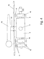
- Fig. 4
- die Anordnung des Verteilerventils in der Ansicht IV-IV,
- Fig. 5
- das Verteilerventil entsprechend Fig. 3, jedoch mit einer anderen Einstellung,
- Fig. 6
- das Verteilerventil entsprechend Fig. 3, jedoch mit einer anderen Einstellung,
- Fig. 7
- das Verteilerventil entsprechend Fig. 3, jedoch mit einer anderen Einstellung,
- Fig. 8
- eine weitere Anordnung des Verteilerventils in Verbindung mit einer Abdeckwand in der Vorderansicht und
- Fig. 9
- die Anordnung des Verteilerventils gemäß Fig. 8 in der Ansicht IX-IX.
Claims (8)
- Landwirtschaftliche Feldspritze mit einem Rahmen, einem Flüssigkeitsbehälter, einer angetriebenen Pumpe, zumindest einer Druckleitung zumindest einer Saugleitung, zumindest einem in zumindest einer der Leitungen angeordneten Verteilerventile, von dem zumindest zwei als Abzweigleitungen ausgebildete Leitungen über das eine Ventilwelle mit Handbetätigungshebel aufweisende Verteilerventil abzweigen, wobei der Betätigungshebel mit rahmenfest angeordneten Einstellmarkierungen und/oder -Bezeichnungen zusammenwirkt, wobei zumindest einer der Abzweigleitungen Handbetätigungselemente aufweisende Absperrventile zugeordnet sind, dadurch gekennzeichnet, dass eine drehfest mit der Ventilwelle (22) und/oder dem Handbetätigungshebel (18) des Verteilerventils (5) verbundene Abdeckscheibe (19) vorgesehen ist, dass die Betätigungselemente (11) der Absperrventile (12) auf einem um die Ventilwelle (22) geschlagenen Kreisbogen (23) und innerhalb des von der Abdeckscheibe (19) bedeckten Bereiches angeordnet sind, dass in der Abdeckscheibe (19) ein Durchbruch (20), der sich in dem Abstand, der dem Abstand der Betätigungselemente (11) der Absperrventile (12) von der Ventilwelle (22) entspricht, von der Ventilwelle (22) befindet, angeordnet ist.
- Feldspritze nach Anspruch 1, dadurch gekennzeichnet, dass der Durchbruch (20) eine derartige Größe aufweist, dass nur die Betätigungselemente (11) / das Betätigungselement (11) einer Abzweigleitung durch den Durchbruch (20) von Hand betätigbar ist.
- Feldspritze nach einem oder mehreren der vorstehenden Ansprüche, dadurch gekennzeichnet, dass eine mit dem Rahmen verbundene Abdeckwand (26) vorgesehen ist, dass hinter der Abdeckwand (26) die Ventile (12) und Abzweigleitungen angeordnet sind, dass die Abdeckwand (26) zumindest einen Ausschnitt (28) aufweist, durch den die Ventilwelle (22) des Verteilerventils (5) ragt, dass der Betätigungshebel (18) vor der Abdeckwand (26) angeordnet ist.
- Feldspritze nach Anspruch 3, dadurch gekennzeichnet, dass die Abdeckscheibe sich vor der Abdeckwand (26) befindet.
- Feldspritze nach Anspruch 3, dadurch gekennzeichnet, dass die Abdeckscheibe (19) sich hinter der Abdeckwand (26) befindet.
- Feldspritze nach Anspruch 3, dadurch gekennzeichnet, dass der Ausschnitt (28) in der Abdeckwand (26) zumindest eine derartige Größe aufweist, dass er den Zugang zu den sich hinter der Abdeckwand (26)angeordneten Betätigungselementen (11) der Absperrventile (12) freigibt.
- Feldspritze nach Anspruch 3, dadurch gekennzeichnet, dass für jedes Betätigungselement (11) der Absperrventile (12) und/oder für jedes Absperrventil (12) ein Ausschnitt (28) vorhanden ist.
- Feldspritze nach Anspruch 3, dadurch gekennzeichnet, dass der Ausschnitt / die Ausschnitte (28) mit dem Durchbruch (20) in der Absteckscheibe (19) wahlweise zur Deckung bringbar sind.
Applications Claiming Priority (2)
| Application Number | Priority Date | Filing Date | Title |
|---|---|---|---|
| DE2003104047 DE10304047A1 (de) | 2003-02-01 | 2003-02-01 | Landwirtschaftliche Feldspritze |
| DE10304047 | 2003-02-01 |
Publications (2)
| Publication Number | Publication Date |
|---|---|
| EP1444893A1 true EP1444893A1 (de) | 2004-08-11 |
| EP1444893B1 EP1444893B1 (de) | 2006-08-23 |
Family
ID=32603092
Family Applications (1)
| Application Number | Title | Priority Date | Filing Date |
|---|---|---|---|
| EP20040001277 Expired - Lifetime EP1444893B1 (de) | 2003-02-01 | 2004-01-22 | Landwirtschaftliche Feldspritze |
Country Status (3)
| Country | Link |
|---|---|
| EP (1) | EP1444893B1 (de) |
| DE (2) | DE10304047A1 (de) |
| DK (1) | DK1444893T3 (de) |
Cited By (3)
| Publication number | Priority date | Publication date | Assignee | Title |
|---|---|---|---|---|
| EP1821017A3 (de) * | 2006-02-15 | 2007-11-07 | Amazonen-Werke H. Dreyer GmbH & Co. KG | Mehrwegeventil |
| EP2789232A3 (de) * | 2013-04-11 | 2015-03-11 | Amazonen-Werke H. Dreyer GmbH & Co. KG | Feldspritze |
| EP2907386A1 (de) * | 2014-02-17 | 2015-08-19 | Amazonen-Werke H. Dreyer GmbH & Co. KG | Flüssigkeits-Fördersystem |
Families Citing this family (2)
| Publication number | Priority date | Publication date | Assignee | Title |
|---|---|---|---|---|
| DE102009026234B4 (de) | 2009-07-23 | 2023-07-06 | Amazonen-Werke H. Dreyer SE & Co. KG | Spritzeinrichtung |
| DE102009026233A1 (de) | 2009-07-23 | 2011-02-03 | Amazonen-Werke H. Dreyer Gmbh & Co. Kg | Spritzeinrichtung |
Citations (5)
| Publication number | Priority date | Publication date | Assignee | Title |
|---|---|---|---|---|
| DE2439248A1 (de) * | 1973-08-17 | 1975-02-27 | Air Liquide | Anschlussvorrichtung fuer stroemungsmittel und deren verwendung bei der niveaumessung und speicherung von fluessigkeiten |
| DE2554713A1 (de) * | 1975-12-05 | 1977-06-08 | Bayer Ag | Vorrichtung zum verriegeln von absperrorganen |
| DE3807099A1 (de) * | 1988-03-04 | 1989-09-14 | Bosch Gmbh Robert | Handbetaetigtes schaltventil |
| EP0428966A1 (de) * | 1989-11-24 | 1991-05-29 | Amazonen-Werke H. Dreyer GmbH & Co. KG | Dosierarmatur für eine landwirtschaftliche Feldspritze |
| EP0623280A1 (de) * | 1993-03-31 | 1994-11-09 | Tecnoma | Steuervorrichtung für eine landwirtschaftliche Feldspritze |
-
2003
- 2003-02-01 DE DE2003104047 patent/DE10304047A1/de not_active Withdrawn
-
2004
- 2004-01-22 DK DK04001277T patent/DK1444893T3/da active
- 2004-01-22 EP EP20040001277 patent/EP1444893B1/de not_active Expired - Lifetime
- 2004-01-22 DE DE200450001224 patent/DE502004001224D1/de not_active Expired - Lifetime
Patent Citations (5)
| Publication number | Priority date | Publication date | Assignee | Title |
|---|---|---|---|---|
| DE2439248A1 (de) * | 1973-08-17 | 1975-02-27 | Air Liquide | Anschlussvorrichtung fuer stroemungsmittel und deren verwendung bei der niveaumessung und speicherung von fluessigkeiten |
| DE2554713A1 (de) * | 1975-12-05 | 1977-06-08 | Bayer Ag | Vorrichtung zum verriegeln von absperrorganen |
| DE3807099A1 (de) * | 1988-03-04 | 1989-09-14 | Bosch Gmbh Robert | Handbetaetigtes schaltventil |
| EP0428966A1 (de) * | 1989-11-24 | 1991-05-29 | Amazonen-Werke H. Dreyer GmbH & Co. KG | Dosierarmatur für eine landwirtschaftliche Feldspritze |
| EP0623280A1 (de) * | 1993-03-31 | 1994-11-09 | Tecnoma | Steuervorrichtung für eine landwirtschaftliche Feldspritze |
Cited By (3)
| Publication number | Priority date | Publication date | Assignee | Title |
|---|---|---|---|---|
| EP1821017A3 (de) * | 2006-02-15 | 2007-11-07 | Amazonen-Werke H. Dreyer GmbH & Co. KG | Mehrwegeventil |
| EP2789232A3 (de) * | 2013-04-11 | 2015-03-11 | Amazonen-Werke H. Dreyer GmbH & Co. KG | Feldspritze |
| EP2907386A1 (de) * | 2014-02-17 | 2015-08-19 | Amazonen-Werke H. Dreyer GmbH & Co. KG | Flüssigkeits-Fördersystem |
Also Published As
| Publication number | Publication date |
|---|---|
| EP1444893B1 (de) | 2006-08-23 |
| DE502004001224D1 (de) | 2006-10-05 |
| DK1444893T3 (da) | 2006-10-23 |
| DE10304047A1 (de) | 2004-08-05 |
Similar Documents
| Publication | Publication Date | Title |
|---|---|---|
| EP3384748B1 (de) | Vorrichtung zum dosieren eines granularen oder körnigen materials in einer verteilmaschine und verteilmaschine | |
| DE102005030781B4 (de) | Schleuderstreuer für Streugut | |
| EP0385926B1 (de) | Vorrichtung zum Ausbringen von Pflanzenschutzmitteln | |
| DE2604836C2 (de) | ||
| EP1444893B1 (de) | Landwirtschaftliche Feldspritze | |
| DE3641080C2 (de) | Schleuderdüngerstreuer | |
| EP1821017A2 (de) | Mehrwegeventil | |
| DE3819419A1 (de) | Zumesseinrichtung fuer dosiervorrichtungen, insbesondere zur sterilisation von verpackungsmaterial bzw. -behaeltern | |
| DE19906824A1 (de) | Mechanische Dosiervorrichtung | |
| EP0432673A2 (de) | Fahrbare Vorrichtung zum Herstellen einer insbesondere zum Versprühen bestimmten, aus Wasser und mindestens einem flüssigen Wirkstoff bestehenden Lösung | |
| DE3318114A1 (de) | Betaetigungsvorrichtung zur zusaetzlichen fernbetaetigung der lageregelung eines hydraulisch krafthebers | |
| EP1749443B1 (de) | Landwirtschaftliches Spritzgerät | |
| DE60108322T2 (de) | Vorrichtung zur Kontrolle des Auslassventils eines Spülkastens | |
| EP3053427A1 (de) | Pneumatische sämaschine | |
| DE102021124705B4 (de) | Vorrichtung zur Desinfektion einer eine Türklinke drückenden Hand | |
| DE4139775A1 (de) | Verfahren zum betreiben einer elektrischen/elektronischen bedienungsanlage fuer landwirtschaftliche maschinen | |
| DE2658451C3 (de) | Vorrichtung zur Flüssigkeitsmengensteuerung bei Feldspritzen | |
| DE3616538C2 (de) | ||
| EP2942107A1 (de) | Kupplungselement | |
| EP2138636A1 (de) | Berieselungsvorrichtung zum dosierbaren Berieseln einer Grundplatte einer Vibrationsvorrichtung zur Bodenverdichtung | |
| DE202017103109U1 (de) | Vorrichtung zur Dosierung von Infusionsbeuteln für medizinische Zwecke sowie Einrichtung zur Befüllung einer Mehrzahl von Leerbehältern | |
| DE4138486C2 (de) | Hydraulikanlage eines landwirtschaftlichen Gerätes | |
| EP1512799B1 (de) | Schwenkbarer Mischwasserauslauf mit wasserführendem Drehgelenk | |
| DE102007063868B3 (de) | Zweischeibenstreuer | |
| EP1308658A2 (de) | Mehrwegehahn |
Legal Events
| Date | Code | Title | Description |
|---|---|---|---|
| PUAI | Public reference made under article 153(3) epc to a published international application that has entered the european phase |
Free format text: ORIGINAL CODE: 0009012 |
|
| AK | Designated contracting states |
Kind code of ref document: A1 Designated state(s): AT BE BG CH CY CZ DE DK EE ES FI FR GB GR HU IE IT LI LU MC NL PT RO SE SI SK TR |
|
| AX | Request for extension of the european patent |
Extension state: AL LT LV MK |
|
| 17P | Request for examination filed |
Effective date: 20041103 |
|
| AKX | Designation fees paid |
Designated state(s): DE DK FR NL |
|
| RBV | Designated contracting states (corrected) |
Designated state(s): DE DK FR NL |
|
| GRAP | Despatch of communication of intention to grant a patent |
Free format text: ORIGINAL CODE: EPIDOSNIGR1 |
|
| GRAS | Grant fee paid |
Free format text: ORIGINAL CODE: EPIDOSNIGR3 |
|
| GRAA | (expected) grant |
Free format text: ORIGINAL CODE: 0009210 |
|
| AK | Designated contracting states |
Kind code of ref document: B1 Designated state(s): DE DK FR NL |
|
| REF | Corresponds to: |
Ref document number: 502004001224 Country of ref document: DE Date of ref document: 20061005 Kind code of ref document: P |
|
| REG | Reference to a national code |
Ref country code: DK Ref legal event code: T3 |
|
| ET | Fr: translation filed | ||
| PLBE | No opposition filed within time limit |
Free format text: ORIGINAL CODE: 0009261 |
|
| STAA | Information on the status of an ep patent application or granted ep patent |
Free format text: STATUS: NO OPPOSITION FILED WITHIN TIME LIMIT |
|
| 26N | No opposition filed |
Effective date: 20070524 |
|
| REG | Reference to a national code |
Ref country code: FR Ref legal event code: PLFP Year of fee payment: 13 |
|
| REG | Reference to a national code |
Ref country code: FR Ref legal event code: PLFP Year of fee payment: 14 |
|
| REG | Reference to a national code |
Ref country code: FR Ref legal event code: PLFP Year of fee payment: 15 |
|
| PGFP | Annual fee paid to national office [announced via postgrant information from national office to epo] |
Ref country code: NL Payment date: 20180115 Year of fee payment: 15 |
|
| PGFP | Annual fee paid to national office [announced via postgrant information from national office to epo] |
Ref country code: DE Payment date: 20180110 Year of fee payment: 15 Ref country code: DK Payment date: 20180110 Year of fee payment: 15 |
|
| PGFP | Annual fee paid to national office [announced via postgrant information from national office to epo] |
Ref country code: FR Payment date: 20181213 Year of fee payment: 16 |
|
| REG | Reference to a national code |
Ref country code: DE Ref legal event code: R119 Ref document number: 502004001224 Country of ref document: DE |
|
| REG | Reference to a national code |
Ref country code: DK Ref legal event code: EBP Effective date: 20190131 |
|
| REG | Reference to a national code |
Ref country code: NL Ref legal event code: MM Effective date: 20190201 |
|
| PG25 | Lapsed in a contracting state [announced via postgrant information from national office to epo] |
Ref country code: DE Free format text: LAPSE BECAUSE OF NON-PAYMENT OF DUE FEES Effective date: 20190801 Ref country code: NL Free format text: LAPSE BECAUSE OF NON-PAYMENT OF DUE FEES Effective date: 20190201 |
|
| PG25 | Lapsed in a contracting state [announced via postgrant information from national office to epo] |
Ref country code: DK Free format text: LAPSE BECAUSE OF NON-PAYMENT OF DUE FEES Effective date: 20190131 |
|
| PG25 | Lapsed in a contracting state [announced via postgrant information from national office to epo] |
Ref country code: FR Free format text: LAPSE BECAUSE OF NON-PAYMENT OF DUE FEES Effective date: 20200131 |