EP1444878A1 - Aufbau für einen Radausleger und Stützträger - Google Patents
Aufbau für einen Radausleger und Stützträger Download PDFInfo
- Publication number
- EP1444878A1 EP1444878A1 EP04100293A EP04100293A EP1444878A1 EP 1444878 A1 EP1444878 A1 EP 1444878A1 EP 04100293 A EP04100293 A EP 04100293A EP 04100293 A EP04100293 A EP 04100293A EP 1444878 A1 EP1444878 A1 EP 1444878A1
- Authority
- EP
- European Patent Office
- Prior art keywords
- wheel boom
- support beam
- structure according
- areas
- wheel
- Prior art date
- Legal status (The legal status is an assumption and is not a legal conclusion. Google has not performed a legal analysis and makes no representation as to the accuracy of the status listed.)
- Granted
Links
- 238000010276 construction Methods 0.000 title claims description 9
- 238000005461 lubrication Methods 0.000 claims description 5
- 230000001050 lubricating effect Effects 0.000 claims 1
- 238000005266 casting Methods 0.000 description 23
- 238000003860 storage Methods 0.000 description 6
- 238000003971 tillage Methods 0.000 description 6
- 230000000712 assembly Effects 0.000 description 4
- 238000000429 assembly Methods 0.000 description 4
- 125000006850 spacer group Chemical group 0.000 description 4
- 238000011161 development Methods 0.000 description 2
- 230000018109 developmental process Effects 0.000 description 2
- 239000004519 grease Substances 0.000 description 2
- 210000002445 nipple Anatomy 0.000 description 2
- 230000003542 behavioural effect Effects 0.000 description 1
- 238000011109 contamination Methods 0.000 description 1
- 238000004519 manufacturing process Methods 0.000 description 1
- 230000003014 reinforcing effect Effects 0.000 description 1
Images


Classifications
-
- A—HUMAN NECESSITIES
- A01—AGRICULTURE; FORESTRY; ANIMAL HUSBANDRY; HUNTING; TRAPPING; FISHING
- A01B—SOIL WORKING IN AGRICULTURE OR FORESTRY; PARTS, DETAILS, OR ACCESSORIES OF AGRICULTURAL MACHINES OR IMPLEMENTS, IN GENERAL
- A01B63/00—Lifting or adjusting devices or arrangements for agricultural machines or implements
- A01B63/14—Lifting or adjusting devices or arrangements for agricultural machines or implements for implements drawn by animals or tractors
- A01B63/16—Lifting or adjusting devices or arrangements for agricultural machines or implements for implements drawn by animals or tractors with wheels adjustable relatively to the frame
- A01B63/22—Lifting or adjusting devices or arrangements for agricultural machines or implements for implements drawn by animals or tractors with wheels adjustable relatively to the frame operated by hydraulic or pneumatic means
Definitions
- the invention relates to a structure for a wheel boom and Support bracket for mounting on a frame agricultural equipment, with the frame transverse to Direction of forward movement of the device extends.
- Multi-part frame of agricultural equipment such as. B.
- Field cultivators or similar tillage machines usually have a main frame and side frame, which are attached to opposite sides of the main frame are.
- Superstructures of dials that have a wheel boom included, which can be swiveled around an axis mounted on the frame connected, support the side frames and make one Lift function ready, with which the device between a raised transport position and a lowered Field work position can be moved.
- the structures of Adjustment wheels can also be used to provide a adjustable depth control of the tillage tools on Serve frame.
- a support bracket for a cylinder swiveling with the axis of the wheel arm connected to rotate about the same axis as the To achieve wheel arms is a support bracket for a cylinder swiveling with the axis of the wheel arm connected to rotate about the same axis as the To achieve wheel arms.
- the upper end of the support beam is with one end of a length-adjustable linkage connected, with the opposite end of the linkage with the frame is connected to the support beam in a to maintain the desired angular position.
- a cylinder is between the wheel boom and the support bracket arranged.
- the object underlying the invention is therein seen to overcome the above problems.
- a structure of the type mentioned at the beginning comprises a first and a second selectable on the frame attachable bracket with wheel boom swivel areas and with Support beam swivel areas, a wheel boom construction with a wheel boom and a wheel boom pivot axis, which for Rotation of the wheel boom around an axis on Wheel boom swivel range is picked up and carried, one upright support beam with lower opening areas that open the support beam pivoting areas are receivable and relative to the support beam pivoting areas essentially about the axis are rotatable, a cylinder for pivoting the Wheel boom construction relative to the support bracket around the axis between the support bracket and the wheel boom construction is mounted, with a rotational movement subject to friction between the support beam and the support beam pivoting areas occurs when a bearing surface of the support beam relative to the Brackets is rotated, the rotation is independent rotation of the wheel boom about the axis can.
- the structure according to the invention for a wheel boom and Support bracket comprises a pair of individual pieces Swivel bearing castings (brackets) which can be selected different places on the frame can be arranged and a Allow pivoting of the wheel boom and the support beam.
- a wheel boom axis extends between the swivel bearing castings (Brackets) and is pivotable with cylindrical trained in the swivel bearing castings Storage areas arranged.
- the support bracket includes a Pair of plates on outside of storage areas located and concentric with the storage areas aligned bearing surfaces are rotatably supported, the Panels include circular openings that extend over the outside storage areas are included.
- the double pivot bearing function as a single piece trained swivel bearing castings offers a simple and relatively inexpensive bearing arrangement for the Wheel boom and the support bracket and eliminated Frictional wear between the support beam and the Wheel boom axis, which otherwise normally occurs, if the wheel boom for lifting and lowering the device is pivoted. Lubrication of a bearing for the Support beams are not required.
- the symmetrical training the swivel bearing castings (brackets) allow use the same part both as right-hand and as left-hand swivel bearing. It can be as simple as Plate arrangement trained support beams are used which are lightweight. Furthermore, a compact, Sturdy bearing construction created that simply different places along the frame can. Attachment and removal of the bearing structure can be relative can be carried out quickly and easily. Compared to the most of the bearing and support structures available to date the structure according to the invention is essentially lighter trained and offers more suitable positioning options to achieve an optimized behavior pattern of the Tillage tool.
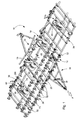
- Figure 1 shows an example of an agricultural device Field cultivator 10, with a main frame 12, which by Pivot wheel assemblies pivotally connected to the frame 12 14, 16 is worn.
- a hitch 18 is provided which is pivotable with a front area of the frame 12 is connected.
- the Adjustment wheel assemblies 14, 16 are hydraulic actuated lifting device 20 connected.
- the Superstructures 34, 36 contain lifting cylinders 44, 46, which in Essentially together with cylinders 48, 50 of the lifting device 20 are operated around the side frame 24, 26 together with the Main frame 12 to raise and lower.
- a more precise one Description of the frame shown in Figure 1 can be found in US Patent application dated December 19, 2002, file number 10 / 326,672 entitled “Implement Lift and Level System with a Front Mounted Direct Coupled Rockshaft " it goes without saying that the frame shown as Example serves and that the superstructures 34, 36 also in connection can be used with other types of frames.
- Assembly 36 includes a pair of identical, convertible swivel bearing castings or Brackets 54, 56 which are rectangular in cross section formed transverse tube 26t, which is part of the Forms side frame 26 are attached.
- Assembly 36 includes a pair of identical, convertible swivel bearing castings or Brackets 54, 56 which are rectangular in cross section formed transverse tube 26t, which is part of the Forms side frame 26 are attached.
- Adjustment boom 58 and a support bracket 60 are of the Castings 54, 56 pivotally carried, each independently one another transversely to the forward direction F extending axis 62 is rotatable.
- a length adjustable Linkage 66 is between an upper end portion of the Support bracket 60 and a bracket 68 attached, the Bracket 68 at a front location or on a frame part 70 (see Figure 1) of the side frame 26 of the device attached is.
- the cylinder 46 has a bottom end, which between the axis 62 and the linkage 66 to the support beam 60 is attached.
- the rod end of the cylinder 46 is with a lower bracket 72 for the setting wheel arm 58 connected, which also receives a wheel assembly 74.
- the brackets 54, 56 are essentially identical trained and shown as uniform castings.
- On Mounting area 80 ( Figure 4) includes surfaces 82, 84 that are in are arranged at right angles to each other so that these to adjoining lower and front surfaces of the support frame part. Openings 86 and 88 take with them Threaded legs of U-shaped bolts 90 on the bolts 90 are around the remaining surfaces of the frame part extend. The legs are provided with bolt nuts 92 to to fix the castings firmly to the frame parts. Reinforcing ribs 94, 96 are provided on the circumference downward and forward direction from the mounting area 80 extend from to a cylindrical bearing receiving area 100.
- the bearing receiving area 100 comprises an axle bearing surface structure 102 with a centrally arranged annular lubrication groove 104, which in connection with a Lubrication channel 106 is available, which opens into a grease nipple 108.
- the grease nipple 108 is arranged so that it is for tools is optimally accessible.
- the end area of the Storage area 100 is closed on one side 110, to protect the bearing receiving area 100 from contamination.
- a cylindrical support bracket bearing or shoulder 112 protrudes axially on the open side of the bearing receiving area 100 and includes a fixed cylindrical bearing surface 114, which is formed centered on the axis 62.
- a cylindrical shaft or wheel boom pivot axis 118 is fixed connected to the wheel arm 58 and includes opposed Ends which are received by the bearing receiving areas 100 and for rotary movements around the axis 62 on the Bearing surface structure 102 are worn.
- the support beam 60 is made of a pair of Essentially identical, upright and in Transversely spaced plates 124, 126 which have lower end regions with openings 128 which extend beyond the Bearing surfaces 114 are pushed. Plates 124, 126 extend upward to a mounting area 130 for the bottom end of the cylinder 46, in which a Swivel pin and a spacer 132 added becomes, for the pivotable connection of the bottom end of the Cylinder 46 between the plates 124, 126 and for compliance a suitable distance between the plates 124, 126 in Mounting area 130. The plates 124, 126 extend continue upward to an assembly area 140 for the linkage 66, which is in front of and above the assembly area 130 is arranged.
- a link pivot pin and one Spacer 142 is provided by openings in the assembly area 140 worn, for the pivotable connection of the rear End region of the linkage 66 with the upper end region of the Support beam 60 and to maintain a suitable distance between the upper end portions of plates 124, 126.
- One Spacer 146 extends between the lower ones End portions of plates 124, 126.
- the spacers 132, 142, 146 keep the plates 124, 126 in relation to each other parallel position.
- the brackets 54, 56 are on the Side frame 26 mounted that the axle bearing surface structure 102 and the bearing surface 114 at a suitable distance are good storage of each other Wheel boom pivot axis 118 and support beam 60 provide.
- the swivel bearing castings (Brackets) 54, 56 When mounting the swivel bearing castings (Brackets) 54, 56 to a desired frame part a place where an optimal Behavioral pattern of tillage tools can be achieved, to avoid interference.
- the swivel bearing castings (Brackets) 54, 56 loosely attached to the frame and the wheel boom pivot axis 118 and the support bracket 60 regarding the pivot bearing castings (brackets) 54, 56 positioned.
- the swivel bearing castings (Brackets) 54, 56 pushed together to the Include the wheel boom pivot axis 118 and the support bracket.
- the bolt nuts 92 are then on the threaded ends of the Bolt 90 tightened around the pivot bearing castings (Brackets) 54, 56 secure in place.
- the Superstructures 34, 36 can be done by simply loosening one or both Swivel bearing castings (brackets) 54, 56 and Pushing apart the swivel bearing castings (brackets) 54, 56 can be taken apart.
- the entire structure 34, 36 can easily on the frame part in the transverse direction be adjusted or moved to another assembly point become.
- a relative rotational movement between the support beam 60 and the bearing surface 114 occurs only when adjustments with respect to the position of the wheel assembly 74 by adjusting the Length of the linkage 66 take place so that on the bearing surfaces 114 no lubrication is required.
- each swivel bearing casting (brackets) 54, 56 bisecting and on axis 62 (see Figure 4) lying area allows the swivel bearing castings (Brackets) 54, 56 with the opening of the bearing receiving areas 100 can be mounted on the left as well as on the right, see above that only a single casting configuration for both Pivot bearing castings (brackets) 54, 56 is required and thus the variety of parts and the manufacturing costs can be reduced.
Landscapes
- Life Sciences & Earth Sciences (AREA)
- Zoology (AREA)
- Engineering & Computer Science (AREA)
- Mechanical Engineering (AREA)
- Soil Sciences (AREA)
- Environmental Sciences (AREA)
- Soil Working Implements (AREA)
- Pivots And Pivotal Connections (AREA)
- Tents Or Canopies (AREA)
- Vehicle Body Suspensions (AREA)
- Agricultural Machines (AREA)
- Transplanting Machines (AREA)
- Conveying And Assembling Of Building Elements In Situ (AREA)
- Jib Cranes (AREA)
Abstract
Description
- Fig. 1
- eine perspektivische Ansicht eines mehrteiligen Gerätes mit einer befestigten Tragkonstruktion für Stützträger und Einstellradaufbauten, mit einigen aus Klarheitsgründen entfernten Bauteilen,
- Fig. 2
- eine vergrößerte perspektivische Vorderansicht der Tragkonstruktion für Stützträger und Einstellradaufbauten aus Figur 1,
- Fig. 3
- eine vergrößerte perspektivische Hinteransicht eines Bereichs der Tragkonstruktion aus Figur 2 und
- Fig. 4
- eine vergrößerte perspektivische Seitenansicht eines in der Tragkonstruktion verwendeten Gussteils.
Claims (14)
- Aufbau für einen Radausleger (58) und Stützträger (60) zur Montage an einen Rahmen (24, 26) eines landwirtschaftlichen Gerätes (10), wobei sich der Rahmen (24, 26) quer zur Richtung einer Vorwärtsbewegung des Gerätes (10) erstreckt, mitwobei eine reibungsbehaftete Drehbewegung zwischen dem Stützträger (60) und den Stützträgerschwenkbereichen auftritt, wenn eine Lagerfläche (114) des Stützträgers (60) relativ zu den Halterungen (54, 56) verdreht wird, und wobei die Drehbewegung unabhängig von einer Drehbewegung des Radauslegers (58) um die Achse (62) erfolgen kann.einer ersten und einer zweiten auswählbar an den Rahmen (24, 26) befestigbaren Halterung (54, 56) mit Radauslegerschwenkbereichen und mit Stützträgerschwenkbereichen,einer Radauslegerkonstruktion mit einem Radausleger (58) und einer Radauslegerschwenkachse (118), die zur Drehung des Radauslegers (58) um eine Achse (62) am Radauslegerschwenkbereich aufgenommen und getragen wird,einem aufrechten Stützträger (60) mit unteren Öffnungsbereichen (128), die auf den Stützträgerschwenkbereichen aufnehmbar sind und relativ zu den Stützträgerschwenkbereichen im Wesentlichen um die Achse (62) drehbar sind,einem Zylinder (46), der zum Schwenken der Radauslegerkonstruktion relativ zum Stützträger (60) um die Achse (62) zwischen dem Stützträger (60) und der Radauslegerkonstruktion montiert ist,
- Aufbau nach Anspruch 1, dadurch gekennzeichnet, dass die erste und zweite Halterung (54, 56) einzelne Bauteile umfassen, welche im Wesentlichen identisch und untereinander austauschbar sind.
- Aufbau nach Anspruch 1 oder 2, dadurch gekennzeichnet, dass die Halterungen (54, 56) einheitliche Gussteile umfassen.
- Aufbau nach einem der vorhergehenden Ansprüche, dadurch gekennzeichnet, dass die Halterungen (54, 56) eine Schmiernut (104) zur Schmierung der Radauslegerschwenkachse aufweisen.
- Aufbau nach einem der vorhergehenden Ansprüche, dadurch gekennzeichnet, dass die Halterungen (54, 56) relativ zu dem Rahmen (24, 26) einzeln montierbar und verschiebbar sind, um eine Positionierung und eine Demontage der Radauslegerkonstruktion zu vereinfachen.
- Aufbau nach einem der vorhergehenden Ansprüche, dadurch gekennzeichnet, dass die Halterungen (54, 56) zylindrisch ausgebildete Lageraufnahmebereiche (100), welche die Radauslegerschwenkbereiche definieren, und von den Lageraufnahmebereichen (100) sich nach außen erstreckende, zylindrisch ausgebildete Absätze (112) aufweisen, welche die Stützträgerschwenkbereiche definieren.
- Aufbau nach Anspruch 6, dadurch gekennzeichnet, dass die Lageraufnahmebereiche (100) eine offene Seite und eine geschlossene Seite (110) aufweisen und die Absätze (112) sich an der offenen Seite erstrecken.
- Aufbau nach einem der Ansprüche 6 oder 7, dadurch gekennzeichnet, dass die Radauslegerschwenkachse (118) fest mit dem Radausleger (58) verbunden ist und drehbar von den Lageraufnahmebereichen (100) aufgenommen wird.
- Aufbau nach einem der vorhergehenden Ansprüche, dadurch gekennzeichnet, dass der Stützträger (60) erste und zweite aufrecht ausgerichtete, zueinander beabstandete Platten (124, 126) aufweist und die Öffnungsbereiche (128) als kreisförmige Bohrungen an den unteren Endbereichen der Platten (124, 126) ausgebildet sind.
- Aufbau nach einem der vorhergehenden Ansprüche, dadurch gekennzeichnet, dass die Stützträgerschwenkbereiche zylindrisch ausgebildete Absätze (112) aufweisen, die sich von den Radauslegerschwenkbereichen erstrecken.
- Aufbau nach Anspruch 10, dadurch gekennzeichnet, dass die Radauslegerschwenkbereiche zylindrisch ausgebildete Lageraufnahmebereiche (100) und die Absätze (112) eine Achse aufweisen, die der Achse (62) entspricht.
- Aufbau nach einem der vorhergehenden Ansprüche, dadurch gekennzeichnet, dass ein längeneinstellbares Element (66) vorgesehen ist, welches zwischen dem Rahmen (24, 26) und dem Stützträger (60) zur Einstellung der Schwenkposition des Stützträgers (60) relativ zu den Halterungen (54, 56) angeordnet ist.
- Aufbau nach Anspruch 12, dadurch gekennzeichnet, dass die reibungsbehaftete Drehbewegung durch Einstellungen des längeneinstellbaren Elements (66) erfolgt.
- Aufbau nach einem der vorhergehenden Ansprüche, dadurch gekennzeichnet, dass die Radauslegerschwenkachse (118) als Zapfen ausgebildet ist.
Applications Claiming Priority (2)
| Application Number | Priority Date | Filing Date | Title |
|---|---|---|---|
| US361723 | 2003-02-06 | ||
| US10/361,723 US6745848B1 (en) | 2003-02-06 | 2003-02-06 | Tower and wheel arm assembly |
Publications (2)
| Publication Number | Publication Date |
|---|---|
| EP1444878A1 true EP1444878A1 (de) | 2004-08-11 |
| EP1444878B1 EP1444878B1 (de) | 2006-04-19 |
Family
ID=32326119
Family Applications (1)
| Application Number | Title | Priority Date | Filing Date |
|---|---|---|---|
| EP04100293A Expired - Lifetime EP1444878B1 (de) | 2003-02-06 | 2004-01-28 | Aufbau für einen Radausleger und Stützträger |
Country Status (7)
| Country | Link |
|---|---|
| US (1) | US6745848B1 (de) |
| EP (1) | EP1444878B1 (de) |
| AR (1) | AR042964A1 (de) |
| BR (1) | BRPI0400344B1 (de) |
| CA (1) | CA2456656C (de) |
| DE (1) | DE502004000432D1 (de) |
| MX (1) | MXPA04000830A (de) |
Families Citing this family (3)
| Publication number | Priority date | Publication date | Assignee | Title |
|---|---|---|---|---|
| US20080110649A1 (en) * | 2006-10-27 | 2008-05-15 | Deere And Company | Folding disk with wing stabilizer wheels |
| DE112010004761T5 (de) * | 2009-12-09 | 2012-11-29 | Cts Corporation | Antriebs- und Sensoranordnung |
| US11419255B2 (en) | 2019-11-04 | 2022-08-23 | Cnh Industrial America Llc | Wheel carrier system |
Citations (4)
| Publication number | Priority date | Publication date | Assignee | Title |
|---|---|---|---|---|
| US4428435A (en) * | 1982-05-10 | 1984-01-31 | Deere & Company | Agricultural implement with hitch control |
| US5488996A (en) * | 1994-07-01 | 1996-02-06 | Kinze Manufacturing, Inc. | Forward-folding, winged, implement frame |
| US6401832B1 (en) * | 2000-04-17 | 2002-06-11 | Deere & Company | Agricultural implement lift wheel structure |
| US20020074139A1 (en) * | 2000-12-19 | 2002-06-20 | Ankenman Thomas W. | Floating hitch for agricaltural implement |
Family Cites Families (8)
| Publication number | Priority date | Publication date | Assignee | Title |
|---|---|---|---|---|
| US4696349A (en) * | 1986-01-31 | 1987-09-29 | J. I. Case Company | Farm implement with frame connected thereto by linkage mechanism |
| US4681335A (en) * | 1986-03-06 | 1987-07-21 | J. I. Case Company | Center pivot hitch assembly |
| US5232054A (en) * | 1991-12-02 | 1993-08-03 | Great Plains Manufacturing, Incorporated | Front folding no-till drill |
| US5740870A (en) * | 1996-04-04 | 1998-04-21 | Kinze Manufacturing, Inc. | Agricultural implement with stacking wings |
| CA2205456A1 (en) * | 1997-05-21 | 1998-11-21 | Flexi-Coil Ltd. | Folding frame implement |
| US6003616A (en) * | 1998-03-20 | 1999-12-21 | Deere & Company | Wheel arm assembly interchangeable between walking beam and straight tandem configurations |
| US6554078B1 (en) * | 2001-06-25 | 2003-04-29 | Mcdonald Kevin G. | Multi-function farm implement for treating soil |
| US6679339B1 (en) * | 2002-12-19 | 2004-01-20 | Deere & Company | Implement lift and level system with a front mounted direct coupled rockshaft |
-
2003
- 2003-02-06 US US10/361,723 patent/US6745848B1/en not_active Expired - Lifetime
-
2004
- 2004-01-27 MX MXPA04000830A patent/MXPA04000830A/es active IP Right Grant
- 2004-01-28 EP EP04100293A patent/EP1444878B1/de not_active Expired - Lifetime
- 2004-01-28 DE DE502004000432T patent/DE502004000432D1/de not_active Expired - Lifetime
- 2004-01-29 AR ARP040100265A patent/AR042964A1/es active IP Right Grant
- 2004-01-30 BR BRPI0400344-6A patent/BRPI0400344B1/pt not_active IP Right Cessation
- 2004-02-02 CA CA002456656A patent/CA2456656C/en not_active Expired - Lifetime
Patent Citations (4)
| Publication number | Priority date | Publication date | Assignee | Title |
|---|---|---|---|---|
| US4428435A (en) * | 1982-05-10 | 1984-01-31 | Deere & Company | Agricultural implement with hitch control |
| US5488996A (en) * | 1994-07-01 | 1996-02-06 | Kinze Manufacturing, Inc. | Forward-folding, winged, implement frame |
| US6401832B1 (en) * | 2000-04-17 | 2002-06-11 | Deere & Company | Agricultural implement lift wheel structure |
| US20020074139A1 (en) * | 2000-12-19 | 2002-06-20 | Ankenman Thomas W. | Floating hitch for agricaltural implement |
Also Published As
| Publication number | Publication date |
|---|---|
| BRPI0400344B1 (pt) | 2011-06-28 |
| BRPI0400344A (pt) | 2005-01-04 |
| MXPA04000830A (es) | 2004-08-11 |
| DE502004000432D1 (de) | 2006-05-24 |
| CA2456656A1 (en) | 2004-08-06 |
| US6745848B1 (en) | 2004-06-08 |
| AR042964A1 (es) | 2005-07-13 |
| CA2456656C (en) | 2008-01-29 |
| EP1444878B1 (de) | 2006-04-19 |
Similar Documents
| Publication | Publication Date | Title |
|---|---|---|
| DE2637444C2 (de) | Kombinierte Bodenbearbeitungsmaschine | |
| DE2428917C3 (de) | Bodenbearbeitungsgerät | |
| EP1147699B1 (de) | Anhebbarer Radzusammenbau für den Rahmen eines landwirtschaftlichen Geräts | |
| DE69705807T2 (de) | Heuwerbungsmaschine | |
| EP4492955B1 (de) | Landwirtschaftliches arbeitsgerät | |
| EP0158151B1 (de) | Geräterahmen für Bodenbearbeitungswerkzeuge | |
| DE3011212A1 (de) | Heuwerbungsmaschine | |
| DE9213091U1 (de) | Kreiselegge | |
| EP0094072A1 (de) | Bodenbearbeitungsgerät | |
| EP1731012B1 (de) | Landmaschine mit nach vorn klappbaren Werkzeugen | |
| DE60112351T2 (de) | Heuwerbungsmaschine | |
| DE69117842T2 (de) | Bodenbearbeitungsmaschine | |
| DE2247055A1 (de) | Bodenbearbeitungsgeraet | |
| EP3165076B1 (de) | Anbaugestell für ein nutzfahrzeug | |
| AT391391B (de) | Bodenbearbeitungsmaschine | |
| EP3649841B1 (de) | Landwirtschaftliche maschine zur bodenbearbeitung | |
| EP1444878B1 (de) | Aufbau für einen Radausleger und Stützträger | |
| DE9010178U1 (de) | Landwirtschaftliches Bodenwalzgerät | |
| DE29714523U1 (de) | Gezogene Mähmaschine mit einer seitlich angehängten Zugstange | |
| EP2113159A1 (de) | Grubber | |
| EP2050323B1 (de) | Aufsatteldrehpflug | |
| DE3337193C2 (de) | ||
| EP0427149B1 (de) | Vorrichtung zum Anbau einer Landmaschine an einen Dreipunktbock | |
| DE102004025478B4 (de) | Landwirtschaftliche Maschine | |
| DE69424828T2 (de) | Gerätekombination zur Bodenbearbeitung und zum Säen deren Sämaschine während des Transportes gut gehalten ist |
Legal Events
| Date | Code | Title | Description |
|---|---|---|---|
| PUAI | Public reference made under article 153(3) epc to a published international application that has entered the european phase |
Free format text: ORIGINAL CODE: 0009012 |
|
| AK | Designated contracting states |
Kind code of ref document: A1 Designated state(s): AT BE BG CH CY CZ DE DK EE ES FI FR GB GR HU IE IT LI LU MC NL PT RO SE SI SK TR |
|
| AX | Request for extension of the european patent |
Extension state: AL LT LV MK |
|
| 17P | Request for examination filed |
Effective date: 20050211 |
|
| AKX | Designation fees paid |
Designated state(s): DE FR GB |
|
| RBV | Designated contracting states (corrected) |
Designated state(s): DE FR GB |
|
| GRAP | Despatch of communication of intention to grant a patent |
Free format text: ORIGINAL CODE: EPIDOSNIGR1 |
|
| GRAS | Grant fee paid |
Free format text: ORIGINAL CODE: EPIDOSNIGR3 |
|
| GRAA | (expected) grant |
Free format text: ORIGINAL CODE: 0009210 |
|
| AK | Designated contracting states |
Kind code of ref document: B1 Designated state(s): DE FR GB |
|
| REG | Reference to a national code |
Ref country code: GB Ref legal event code: FG4D Free format text: NOT ENGLISH |
|
| REF | Corresponds to: |
Ref document number: 502004000432 Country of ref document: DE Date of ref document: 20060524 Kind code of ref document: P |
|
| GBT | Gb: translation of ep patent filed (gb section 77(6)(a)/1977) |
Effective date: 20060512 |
|
| ET | Fr: translation filed | ||
| PLBE | No opposition filed within time limit |
Free format text: ORIGINAL CODE: 0009261 |
|
| STAA | Information on the status of an ep patent application or granted ep patent |
Free format text: STATUS: NO OPPOSITION FILED WITHIN TIME LIMIT |
|
| 26N | No opposition filed |
Effective date: 20070122 |
|
| PGFP | Annual fee paid to national office [announced via postgrant information from national office to epo] |
Ref country code: GB Payment date: 20140127 Year of fee payment: 11 |
|
| GBPC | Gb: european patent ceased through non-payment of renewal fee |
Effective date: 20150128 |
|
| PG25 | Lapsed in a contracting state [announced via postgrant information from national office to epo] |
Ref country code: GB Free format text: LAPSE BECAUSE OF NON-PAYMENT OF DUE FEES Effective date: 20150128 |
|
| REG | Reference to a national code |
Ref country code: FR Ref legal event code: PLFP Year of fee payment: 13 |
|
| REG | Reference to a national code |
Ref country code: FR Ref legal event code: PLFP Year of fee payment: 14 |
|
| REG | Reference to a national code |
Ref country code: FR Ref legal event code: PLFP Year of fee payment: 15 |
|
| PGFP | Annual fee paid to national office [announced via postgrant information from national office to epo] |
Ref country code: FR Payment date: 20230125 Year of fee payment: 20 |
|
| PGFP | Annual fee paid to national office [announced via postgrant information from national office to epo] |
Ref country code: DE Payment date: 20221221 Year of fee payment: 20 |
|
| REG | Reference to a national code |
Ref country code: DE Ref legal event code: R071 Ref document number: 502004000432 Country of ref document: DE |