EP1444779B1 - Mikroelektromechanischer resonator mit abstimmbarem luftspalt und verfahren zu dessen abstimmung - Google Patents
Mikroelektromechanischer resonator mit abstimmbarem luftspalt und verfahren zu dessen abstimmung Download PDFInfo
- Publication number
- EP1444779B1 EP1444779B1 EP02788056A EP02788056A EP1444779B1 EP 1444779 B1 EP1444779 B1 EP 1444779B1 EP 02788056 A EP02788056 A EP 02788056A EP 02788056 A EP02788056 A EP 02788056A EP 1444779 B1 EP1444779 B1 EP 1444779B1
- Authority
- EP
- European Patent Office
- Prior art keywords
- gap
- constituting
- resonator
- signal electrode
- operating
- Prior art date
- Legal status (The legal status is an assumption and is not a legal conclusion. Google has not performed a legal analysis and makes no representation as to the accuracy of the status listed.)
- Expired - Lifetime
Links
- 238000000034 method Methods 0.000 title claims abstract description 64
- 230000008569 process Effects 0.000 claims abstract description 28
- 238000005530 etching Methods 0.000 claims abstract description 25
- 238000006073 displacement reaction Methods 0.000 claims abstract description 16
- 230000003042 antagnostic effect Effects 0.000 claims abstract description 4
- 239000000758 substrate Substances 0.000 claims description 11
- 238000004873 anchoring Methods 0.000 claims description 9
- 239000004020 conductor Substances 0.000 claims description 3
- 230000000284 resting effect Effects 0.000 claims 4
- 238000009877 rendering Methods 0.000 claims 1
- 230000005540 biological transmission Effects 0.000 description 6
- 238000005516 engineering process Methods 0.000 description 6
- 238000004519 manufacturing process Methods 0.000 description 5
- 229910021420 polycrystalline silicon Inorganic materials 0.000 description 5
- 238000000926 separation method Methods 0.000 description 5
- 238000013461 design Methods 0.000 description 4
- XUIMIQQOPSSXEZ-UHFFFAOYSA-N Silicon Chemical compound [Si] XUIMIQQOPSSXEZ-UHFFFAOYSA-N 0.000 description 3
- 239000000470 constituent Substances 0.000 description 3
- 229910052710 silicon Inorganic materials 0.000 description 3
- 239000010703 silicon Substances 0.000 description 3
- 230000000694 effects Effects 0.000 description 2
- 238000001459 lithography Methods 0.000 description 2
- 238000005259 measurement Methods 0.000 description 2
- 238000005459 micromachining Methods 0.000 description 2
- 230000010287 polarization Effects 0.000 description 2
- 229920005591 polysilicon Polymers 0.000 description 2
- 239000010409 thin film Substances 0.000 description 2
- 230000026683 transduction Effects 0.000 description 2
- 238000010361 transduction Methods 0.000 description 2
- 230000009471 action Effects 0.000 description 1
- 238000010420 art technique Methods 0.000 description 1
- 238000010586 diagram Methods 0.000 description 1
- 239000003989 dielectric material Substances 0.000 description 1
- 239000006185 dispersion Substances 0.000 description 1
- 230000005284 excitation Effects 0.000 description 1
- 238000013213 extrapolation Methods 0.000 description 1
- 239000010408 film Substances 0.000 description 1
- 238000011835 investigation Methods 0.000 description 1
- 230000000873 masking effect Effects 0.000 description 1
- 239000000463 material Substances 0.000 description 1
- 230000004048 modification Effects 0.000 description 1
- 238000012986 modification Methods 0.000 description 1
- 230000009467 reduction Effects 0.000 description 1
- 239000002210 silicon-based material Substances 0.000 description 1
- 239000007787 solid Substances 0.000 description 1
- 230000017105 transposition Effects 0.000 description 1
Images

Classifications
-
- H—ELECTRICITY
- H03—ELECTRONIC CIRCUITRY
- H03H—IMPEDANCE NETWORKS, e.g. RESONANT CIRCUITS; RESONATORS
- H03H9/00—Networks comprising electromechanical or electro-acoustic elements; Electromechanical resonators
- H03H9/02—Details
- H03H9/02244—Details of microelectro-mechanical resonators
- H03H9/02393—Post-fabrication trimming of parameters, e.g. resonance frequency, Q factor
- H03H9/02417—Post-fabrication trimming of parameters, e.g. resonance frequency, Q factor involving adjustment of the transducing gap
-
- H—ELECTRICITY
- H03—ELECTRONIC CIRCUITRY
- H03H—IMPEDANCE NETWORKS, e.g. RESONANT CIRCUITS; RESONATORS
- H03H9/00—Networks comprising electromechanical or electro-acoustic elements; Electromechanical resonators
- H03H9/02—Details
- H03H9/02244—Details of microelectro-mechanical resonators
- H03H2009/02488—Vibration modes
- H03H2009/02496—Horizontal, i.e. parallel to the substrate plane
Definitions
- the separation intervals mentioned above must be able to reach the lowest values, in particular separation interval values well below the usual resolution of microgravure processes implemented.
- the aforementioned resonator is suspended on flexible beams and electrostatically attracted by a buried electrode, in a direction orthogonal to the planar dimension of the substrate.
- the technique described makes it possible to reduce the gap of the resonator from 1.5 ⁇ m to 0.3 ⁇ m.
- micromechanical structures with thick layers and their application to the production of electromechanical resonators according to the techniques of the prior art is therefore very difficult, the implementation of evolving structures can not, for this reason , be considered.
- the object of the present invention is to overcome the drawbacks and limitations of the prior art techniques by implementing a method of adjusting the spacing of two mechanical elements of a substantially plane micromechanical structure which makes it possible to adjust the separation interval values of micromechanical structure elements at values much smaller than the resolution of the microgravure process used for producing such micromechanical structures.
- Another object of the present invention is the implementation of a method for adjusting the spacing of two mechanical elements of a substantially flat micromechanical structure made in thin film or thick film technology or thanks to any type of technology. Because of the substantially flat structure of the aforementioned mechanical structure.
- Another object of the present invention is also the implementation of an electromechanical resonator circuit of substantially flat configuration having, for this reason, a very high reliability and a great deal of tuning dynamics in radio frequency.
- Another object of the present invention is also the implementation of an electromechanical resonator circuit, the resonance radio frequency of which can be adjusted with great precision by applying a control voltage of reduced value.
- object of the present invention applies to mechanical elements formed by one element and another element of this structure each comprising a face, or edge, substantially flat facing and having a residual gap substantially equal to the resolution of the micro-etching process.
- this other element also consists in connecting this other element to the fixed reference position by an elastic connection, this other element in the presence of this elastic connection occupying a rest position for which the spacing between each substantially flat face opposite is substantially equal to the residual gap. It then consists in installing, between the element constituting the fixed reference position in the structure and the other element made free, at least one abutment wedge, so as to arrange between the other element and this abutment wedge a spacing stopper defining the maximum displacement amplitude of this other element between the rest position and a stop position constituting the operating position.
- the other element is then subjected to an opposing movement at the elastic connection to the stop position constituting the operating position, the residual gap being thus reduced to an operating gap equal to the difference between this residual gap and the stop gap and less than the resolution of the micro-etching process.
- the electromechanical resonator circuit with adjustable lateral air gap, object of the present invention is remarkable in that it comprises at least, formed by a micro-etching process on a dielectric substrate and arranged in a substantially flat structure, an electrically resonator element conductor anchored in a structure having a fixed reference position, another element constituting a signal electrode, the resonator element and the other element each having a substantially flat face facing each other separated by a residual gap substantially equal to the resolution of the micro-etching process.
- This other element has a degree of freedom in the direction of the residual gap.
- An anchor element of this other signal electrode component is provided and at least one resilient connection connects the other signal electrode component and anchor element.
- the other element constituting the signal electrode in the presence of the elastic connection occupies a rest position for which the spacing between each substantially flat face facing is substantially equal to the residual gap.
- a stop block is further installed between the structure having a fixed reference position and this other element constituting signal electrode, so as to arrange between the other element and the abutment shim an abutment spacing, defining the maximum displacement amplitude of the other element between the rest position and a stop position, constituting the operating position.
- Application circuits, between this other element constituting a signal electrode and a fixed electrode with respect to the resonator element, of an electric potential difference make it possible to constitute an electrostatic motor with adjustable air gap as a function of the difference in applied potential, electrostatic motor formed by the resonator element or an auxiliary electrode, the other element constituting the signal electrode and the elastic connection.
- the electrostatic motor reduces the residual gap to an operating gap equal to the difference between this residual gap and the abutment spacing and less than the resolution of the microgravure process.
- the method and the resonator circuit of the invention are applicable to the manufacture of electromechanical filters or resonators for generating or discriminating radio frequency signals in frequency bands between 10 MHz and 100 MHz, for example.
- a micromechanical structure such as an electromechanical resonator for example, is considered to be formed on a micromechanical structure that is substantially plane and obtained by micro-etching.
- the mechanical elements of the micromechanical structure are formed by an element E and by another element E E each element comprising, for example, a substantially flat face or edge, each of the abovementioned faces being opposite and having a residual spacing obtained by virtue of engraving process or micro-etching used. This residual gap is substantially equal to the resolution of the micro-etching process for this reason.
- the aforementioned residual gap is the limit value of the gap of the micromechanical resonator, this spacing thus corresponding to a lower limit of the distance value and the gap value finally obtained by the sole implementation of the microgravure process.
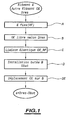
- the method, object of the invention of adjusting the operating distance of two mechanical elements, such as the element E, and the other element, OE, consists from their respective position and from the residual spacing Dres separating them, to be attributed to a step A to one of the elements, the element E for example , a fixed position called RF reference in the aforementioned micromechanical structure.
- Step A is followed by a step B consisting in making free, according to at least one degree of freedom, in the direction of the aforementioned residual distance Dres, the other element OE with respect to the element E and of course by relative to the reference fixed position of the latter.
- Step B is followed by a step C of connecting the other element OE, made free, to the fixed reference position RF by an elastic connection S.
- the other element OE, in the presence of the link and the link elastic S occupies a rest position for which the spacing between each substantially flat face facing is substantially equal to the residual spacing Dres.
- Step C can then be followed by a step D consisting in installing between the element E, constituting the fixed reference position RF, and the other element made free, OE, at least one stop block B so as to between the other element OE and the abutment block B, a stop spacing start.
- the abutment spacing is chosen so as to have a determined value making it possible to define the maximum displacement amplitude of the other element, OE, between the rest position and the stop position constituting the operating position.
- Step D is then followed by a step DE consisting of subjecting the other element OE to a displacement that is opposite to the elastic connection S to the stop position constituting the operating position.
- the method that is the subject of the present invention can advantageously be implemented for adjusting the operating gap of an electromechanical resonator and in particular of the air gap of the latter.
- the element E and the other element E E consist of an electrically conductive material obtained for example by micro-etching of a poly-silicon substrate, reported on an electrical substrate for example, in accordance with the micro-etching technique of integrated circuits.
- the step consisting in subjecting the other element, OE, to an antagonistic displacement to the elastic connection S as represented in step E of FIG. figure 1 may advantageously consist in applying between the other element OE and a fixed electrode FE linked to the element E, in particular to the fixed position of reference RF, a specific electrical potential difference.
- the assembly formed by the fixed electrode bonded to the element E, the other element OE and the elastic connection S and the applied electrical potential difference constitute an electrostatic motor with adjustable air gap.
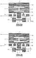
- the set of elements is represented in plan view, the elements made of electrically conductive poly-silicon material being represented in gray in the plane of the figure and consisting of strips of polysilicon material attached to an electrical substrate. not shown in the drawing.
- the anchoring of the element E constituting a resonator is carried out with respect to RF mechanical masses ensuring the aforementioned fixed position and that the other element E E constituting the signal electrode, is in fact subdivided.
- the other element OE constituting the signal electrode and the anchoring part constituting the fixed reference position RF being mechanically connected by the elastic connection constituted by two meander elements S on the Figures 2a and 2b .
- the electric potential difference applied between the fixed electrode FE and the anchoring element ensuring the fixed reference position RF of the other element OE constituting the signal electrode is substantially nothing.
- the gap between the element E and the other element OE constituting the signal electrode corresponds to the residual spacing Dres.
- the electrostatic motor thus constituted makes it possible to move the other element, OE, constituting the signal electrode made mobile towards the element, E, and thereby reduce the value of the gap to the working gap e under the conditions previously mentioned in the description.
- the end position corresponds to the abutment position on the abutment shims B placed for example in the vicinity of the fixed electrode FE.
- the method that is the subject of the present invention would appear to be particularly advantageous when the micromechanical structure constituting the structure of an electromechanical resonator, and in particular the element constituting the resonator element E, the other element OE constituting the signal electrode. and the elastic connection are formed by substantially planar electrically conductive structures on an electrical substrate.
- the mechanical resonance frequency of the element E constituting the resonator, represents the operating frequency of the signal of the resonator in lateral vibration mode.
- the resonator circuit and the electromechanical resonator with adjustable lateral air gap comprise electrically conductive mechanical elements formed by a process of micro-etching on a substrate of electrical, these elements being arranged in a substantially flat structure.
- the element E constitutes an electrically conductive resonator element and is anchored in a structure representing the fixed reference position RF.
- the other element OE and the element E resonator have a face or a plane edge opposite and are separated in the rest position, that is to say in the absence of displacement application of the other constituent element the signal electrode, of the residual gap previously mentioned in the description.
- the other element OE is separated, that is to say, detached from the fixed reference position RF, so as to have a degree of freedom in the directions of the aforementioned residual spacing.
- it is connected by an elastic connection, such as a spring S for example, formed by a polysilicon meander structure.
- the aforementioned meandering structure may consist of two elementary meander structures arranged symmetrically with respect to a longitudinal axis of symmetry X'X of the aforementioned resonator circuit.
- the meander structures connect the other element OE, constituting the signal electrode, to the anchor element constituting the fixed reference position for the latter.
- stop blocks B these are installed between the structure having the reference position and the other element OE constituting a signal electrode so as to arrange, between this other element OE and the where the shims of abutment B, a stop gap as previously mentioned in the description.
- the abutment gap defines the maximum displacement amplitude of the other element OE, that is to say of the signal electrode, between the rest position and the stop position constituting the operating position.
- the resonator circuit as represented in Figure 2a or 2b comprises circuits for applying the potential difference, a continuous potential difference between the other element, OE, and a fixed electrode, FE, mechanically secured to the element E via the fixed reference position RF for constitute the electrostatic motor, as mentioned previously in the description.
- circuits for applying the potential difference are represented schematically by electrical lines connected to the fixed electrode FE respectively to the anchoring part ensuring the fixed position RF reference for the other element OE constituting the signal electrode.
- the signal electrode constituted by the other element OE is not directly subjected to the bias voltage for applying the above-mentioned potential difference but via the elastic connection formed by the S springs.
- the latter Under the action of fields electrostatic thus created between the electrodes of the motor, fixed electrode FE and signal electrode formed by the other element OE, the latter is close to the fixed electrode FE and the element E forming resonator and is positioned in the operating position, that is to say on the stop blocks B.
- the working gap e verifies the previously mentioned relationship in the description, which is constituted by the difference between two spacings generated by the micro-etching process. This operating distance then has values well below the micro-etching gaps which are the distance limits inherent to the micro-etching process used.
- the method which is the subject of the present invention makes it possible to use resonator circuits industrially because, in particular, of the insensitivity of the method which is the subject of the present invention to the phenomenon of overgraving of the structural layer.
- the edges of structure or microstructure are consumed over a width close to 3 to 5% of the thickness to be etched, that is to say between 0.6 ⁇ m and 1 ⁇ m. ⁇ m lateral etching, for a 20 ⁇ m thick layer.
- This phenomenon of lateral supergravation causes a reduction in size of the engraved elements and increases the width of all the spacings.
- the width of silicon consumed on the edges is therefore unpredictable because it depends on the conditions of the microgravure process but remains constant on neighboring patterns. Such a phenomenon of overgrafting does not therefore make it possible to provide precise dimensioning of the structures and spacings associated with the latter.
- the implementation of the method which is the subject of the present invention, makes it possible to define resonators comprising operating gaps, that is to say operating airgaps between the element E constituting the resonator and the other EO element constituting the signal electrode, which are determined by the difference between the widths of two residual spacings. Since the surgraving phenomenon known from the prior art is of course present and constant for the two spacings, the effect of this phenomenon vanishes by difference and the phenomenon of overgrafting is therefore substantially eliminated and does not appear on the final value. of the spacing of operation. Under these conditions, the final gap is defined solely by the lithography masks.
- the lithography masks make it possible to define not only the abovementioned displacements but also the thicknesses of abutment wedges which, of course, determine the displacement value of the signal electrode constituted by the other element OE .
- the figure 3 represents an electromechanical resonator realized thanks to the implementation of the method which is the subject of the present invention.
- the electromechanical resonator object of the present invention comprises a first resonator circuit, designated resonator circuit A, and a second resonator circuit, designated resonator circuit B, as previously described in the description in conjunction with Figures 2a and 2b .
- the resonator circuits A and B are arranged head-to-tail symmetrically with respect to an axis Y'Y orthogonal to the longitudinal axis of symmetry X'X.
- each resonator circuit comprises a first and a second spring Sa1 Sa2 respectively Sb1 Sb2 each providing an elastic connection and a set of stop blocks Ba1, B'a1 respectively Bb1, B'b1. They allow to maintain in the operating position of the other element OE OE has b respectively constituting the signal electrode of each resonator circuit.
- the resonator as represented in figure 3 was implemented from two substantially identical resonator circuits of the type embedded beam in lateral vibration mode and had the following dimensions: length 40 ⁇ m, width 3 ⁇ m, thickness 15 ⁇ m, these dimensions being the design dimensions without taking into account the phenomenon of surgravure, which is substantially eliminated through the implementation of the method object of the present invention.
- the residual gap was 1.8 ⁇ m while for the other resonator, the same residual gap was 2 ⁇ m for an operating gap of 0. , 4 ⁇ m.
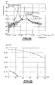
- the Figures 4a and 4b allow to represent certain experimental results relating to the resonator implemented in accordance with the figure 3 for each resonator.
- the figure 4a represents the transmission characteristic of each resonator, as a function of the frequency of the excitation, at bias voltage of each constant resonator circuit.
- the ordinate axis is graduated in attenuation that is to say in dB and the abscissa axis in frequency.
- the figure 4b represents the characteristic of the evolution of the resonance frequency of each resonator, the ordinate axis being graduated in frequency and the abscissa axis in voltage value or potential difference applied.
- the natural frequency of the resonator circuits and the resonators corresponds to a substantially zero polarization. This natural frequency is obtained by extrapolation of the curves of the figure 4b . A bias voltage or zero applied potential difference causing amplitudes too low to be detected. While in theory the eigenfrequencies of the two resonators should be substantially identical, the difference between them, about 2%, is attributable to dispersions related to microfabrication techniques.
- the slope of the curve corresponding to the resonator having the operating gap reduced to 0.2 microns is much steeper than that of the resonator whose operating gap is reduced to only 0.4 microns.
- This effect unambiguously demonstrates a better transduction coefficient for the resonator having the smallest operating distance. Due to the fact that all other parameters of transduction of the two resonators are identical, it is deduced that the residual difference is smaller for the resonator designed for an operating gap of 0.2 microns. Such measurements make it possible to qualitatively certify the improvements made by the method that is the subject of the present invention and the resonator and resonator circuits thus obtained.
- the electrostatic motor architecture used makes it possible to obtain submicron operating distances, while using standard technologies of silicon microgravure with a single structural layer, the structural layer of poly-silicon being reported on a dielectric material for example.
Landscapes
- Physics & Mathematics (AREA)
- Acoustics & Sound (AREA)
- Micromachines (AREA)
- Piezo-Electric Or Mechanical Vibrators, Or Delay Or Filter Circuits (AREA)
Claims (8)
- Verfahren zur Abstimmung bzw. Einstellung des Betriebsabstands zweier mechanischer Elemente einer durch ein Mikroätzverfahren hergestellten, im Wesentlichen planen mechanischen Struktur, wobei die genannten mechanischen Elemente durch ein Element beziehungsweise ein anderes Element gebildet werden, von denen jedes eine im Wesentlichen plane Seite umfasst, sich gegenüberstehend und einen Restabstand (Dres) aufweisend, der im Wesentlichen der Auflösung des genannten Mikroätzverfahrens entspricht,
wobei das genannte Verfahren wenigstens darin besteht:dem einen der genannten Elemente (E) eine feste Bezugsposition in der genannten Struktur zuzuordnen;- das genannte andere Element (OE) in Bezug auf das genannte Element gemäß wenigstens eines Freiheitsgrades in der Richtung des genannten Restabstands frei zu machen;- das genannte andere Element mit der festen Bezugsposition durch eine elastische Verbindung (S) zu verbinden, wobei das andere Element in Präsenz der genannten elastischen Verbindung eine Ruheposition einnimmt, für die der Abstand zwischen den sich gegenüberstehenden planen Seiten im Wesentlichen gleich dem genannten Restabstand ist;dadurch gekennzeichnet, dass es außerdem darin besteht:- wenigstens einen Anschlag (B) einzurichten, zwischen dem in der genannten Struktur die genannte feste Bezugsposition bildenden genannten Element und dem genannten freigemachten anderen Element, um zwischen dem genannten anderen Element und dem genannten wenigstens einen Anschlag einen Anschlagsabstand von bestimmtem Wert zu schaffen, der die maximale Verschiebungsamplitude des genannten anderen Elements zwischen der genannten Ruheposition und einer die Betriebsposition bildenden Anschlagsposition definiert;- das genannte andere Element einer zu der elastischen Verbindung antagonistischen Verschiebung bis zu der genannten die Betriebsposition bildenden Anschlagsposition zu unterwerfen, was ermöglicht, den genannten Restabstand zu reduzieren bis auf einen Betriebsabstand (e) gleich der Differenz zwischen diesem Restabstand und dem genannten Anschlagsabstand und kleiner als die Auflösung des genannten Mikroätzverfahrens. - Verfahren nach Anspruch 1, dadurch gekennzeichnet, dass das genannte Element (E) und das genannte andere Element (OE) durch ein elektrisch leitfähiges Material gebildet werden, wobei der darin bestehende Schritt, die genannte elastische Verbindung (S) einer antagonistischen Verschiebung zu unterwerfen, darin besteht, zwischen dem genannten anderen Element und einer mit dem genannten Element verbundenen festen Elektrode eine elektrisches Potential- bzw. Spannungsdifferenz anzulegen, wobei das Ganze, gebildet durch die mit dem genannten anderen Element verbundene feste Elektrode, das genannte andere Element, die genannte wenigstens eine elastische Verbindung und die genannte angelegte elektrische Potential- bzw. Spannungsdifferenz, einen elektrostatischen Motor mit justierbarem Luftspalt bildet.
- Verfahren nach Anspruch 2, dadurch gekennzeichnet, dass die einen elektromechanischen Resonator bildende genannte Struktur, das das genannte Resonatorelement bildende Element (E), das die Signalelektrode bildende andere Element (OE) und die elastische Verbindung (S) durch im Wesentlichen plane elektrisch leitfähige Strukturen auf einem dielektrischen Substrat ausgebildet werden, wobei die mechanische Resonanzfrequenz des genannten Elements die Betriebsfrequenz des Signals des genannten Resonators im Lateralschwindungsmodus darstellt.
- Elektromechanischer Resonatorkreis mit justierbarem seitlichem Luftspalt, ausgebildet durch ein Mikroätzverfahren auf einem dielektrischen Substrat und angeordnet gemäß einer im Wesentlichen planen Struktur, umfassend:wenigstens ein elektrisch leitfähiges Resonatorelement (E), verankert in einer Struktur mit einer festen Bezugsposition;- ein die Signalelektrode bildendes anderes Element (OE), wobei das Resonatorelement und das andere Element jeweils eine im Wesentlichen plane Seite aufweisen, sich gegenüberstehend und getrennt durch einen Restabstand (Dres) im Wesentlichen gleich der Auflösung des genannten Mikroätzverfahrens, wobei das andere Element in der Richtung des genannten Restabstands einen Freiheitsgrad aufweist;- ein Verankerungselement (RF) des die Signalelektrode bildenden anderen Elements;- wenigstens eine elastische Verbindung (S), die das die Signalelektrode bildende andere Element und das genannte Verankerungselement des die Signalelektrode bildenden anderen Elements verbindet, wobei das die Signalelektrode bildende andere Element in Präsenz der genannten wenigstens einen elastischen Verbindung eine Ruheposition einnimmt, für die der Abstand zwischen den sich gegenüberstehenden planen Seiten im Wesentlichen gleich dem genannten Restabstand ist;dadurch gekennzeichnet, dass er außerdem umfasst:- wenigstens einen Anschlag (B), eingerichtet zwischen der eine Bezugsposition aufweisenden genannten Struktur und dem genannten die Signalelektrode bildenden anderen Element, um zwischen dem genannten anderen Element und dem genannten wenigstens einen Anschlag einen Anschlagsabstand (e) von bestimmtem Wert zu schaffen, der die maximale Verschiebungsamplitude des genannten anderen Elements zwischen der genannten Ruheposition und der die Betriebsposition bildenden Anschlagsposition definiert;- Einrichtungen (RF, FE) zum Anlegen einer elektrischen Potential- bzw. Spannungsdifferenz zwischen dem die Signalelektrode bildenden anderen Element und einer dem genannten Resonatorelement gegenüberstehenden festen Elektrode, wobei das Ganze, gebildet durch das genannte Resonatorelement, das die Signalelektrode bildende andere Element, die wenigstens eine elastische Verbindung und die genannten Einrichtungen zum Anlegen einer Potential- bzw. Spannungsdifferenz, einen elektrostatischen Motor mit in Abhängigkeit von der angelegten Potential- bzw. Spannungsdifferenz justierbarem Luftspalt bildet, was ermöglicht, den genannten Restabstand zu reduzieren bis auf einen Betriebsabstand gleich der Differenz zwischen diesem Restabstand und dem genannten Anschlagsabstand und kleiner als die Auflösung des genannten Mikroätzverfahrens.
- Resonatorkreis nach Anspruch 4, dadurch gekennzeichnet, dass die mechanische Resonanzfrequenz des genannten Elements die Betriebsfrequenz des Signals des genannten Resonatorkreises im Lateralschwingungsmodus darstellt.
- Resonatorkreis nach einem der Ansprüche 4 oder 5, dadurch gekennzeichnet, dass dieser eine in Bezug auf eine zu der Richtung des Restabstands (Dres) im Wesentlichen parallelen Längssymmetrieachse (x'x) im Wesentlichen symmetrische Struktur aufweist.
- Resonatorkreis nach Anspruch 6, dadurch gekennzeichnet, dass dieser in symmetrischer Anordnung, bezogen auf die Längssymmetrieachse, umfasst:- eine erste (Sa1, Sb1) und eine zweite (Sa2, Ab2) Feder, von denen jede eine elastische Verbindung gewährleistet;- einen Satz von zwei Anschlägen (Ba1, B'a1; Bb1, B'b1), die ermöglichen, das die Signalelektrode bildende andere Element (OEa, OEb) in der Betriebsposition zu halten.
- Elektromechanischer Resonator mit seitlichem Luftspalt, dadurch gekennzeichnet, dass er umfasst:- einen ersten Resonatorkreis (A) nach einem der Ansprüche 4 bis 7, und gegenüber, symmetrisch zum ersten Resonatorkreis,- einen zweiten Resonatorkreis (B) nach einem der Ansprüche 4 bis 7, entgegengesetzt angeordnet in Bezug auf den ersten Resonator.
Applications Claiming Priority (3)
| Application Number | Priority Date | Filing Date | Title |
|---|---|---|---|
| FR0114798A FR2832270B1 (fr) | 2001-11-15 | 2001-11-15 | Procede de reglage de l'ecartement de deux elements mecaniques d'une structure micromecanique sensiblement plane et resonateur electromecanique correspondant |
| FR0114798 | 2001-11-15 | ||
| PCT/FR2002/003902 WO2003043189A2 (fr) | 2001-11-15 | 2002-11-14 | Resonateur electromecanique e entrefer lateral ajustable et procede de reglage du meme |
Publications (2)
| Publication Number | Publication Date |
|---|---|
| EP1444779A2 EP1444779A2 (de) | 2004-08-11 |
| EP1444779B1 true EP1444779B1 (de) | 2011-05-04 |
Family
ID=8869442
Family Applications (1)
| Application Number | Title | Priority Date | Filing Date |
|---|---|---|---|
| EP02788056A Expired - Lifetime EP1444779B1 (de) | 2001-11-15 | 2002-11-14 | Mikroelektromechanischer resonator mit abstimmbarem luftspalt und verfahren zu dessen abstimmung |
Country Status (7)
| Country | Link |
|---|---|
| US (1) | US7893595B2 (de) |
| EP (1) | EP1444779B1 (de) |
| JP (1) | JP4351055B2 (de) |
| AU (1) | AU2002352338A1 (de) |
| DE (1) | DE60239951D1 (de) |
| FR (1) | FR2832270B1 (de) |
| WO (1) | WO2003043189A2 (de) |
Families Citing this family (14)
| Publication number | Priority date | Publication date | Assignee | Title |
|---|---|---|---|---|
| AU2003275159A1 (en) | 2002-09-23 | 2004-04-08 | Georgia Tech Research Corporation | Electrically-coupled micro-electro-mechanical filter systems and methods |
| CN103088038B (zh) | 2004-07-12 | 2015-06-24 | 美国天甲生物医药有限公司 | 黄病毒疫苗 |
| DE102004058103B4 (de) * | 2004-12-01 | 2011-03-17 | Technische Universität Chemnitz | Einrichtung zur Spalteinstellung |
| JP2009094690A (ja) * | 2007-10-05 | 2009-04-30 | Seiko Instruments Inc | 発振子及び該発振子を有する発振器 |
| US8111108B2 (en) * | 2008-07-29 | 2012-02-07 | Sand9, Inc. | Micromechanical resonating devices and related methods |
| DE102008040854A1 (de) | 2008-07-30 | 2010-02-04 | Robert Bosch Gmbh | Mikromechanische Struktur sowie Verfahren zum Einstellen der Arbeitsspaltbreite einer mikromechanischen Struktur |
| CN101792108B (zh) * | 2010-03-16 | 2011-12-21 | 杭州电子科技大学 | 一种基于滑膜阻尼的大电容微惯性传感器及其制作方法 |
| EP2395533B1 (de) | 2010-06-09 | 2014-04-30 | Fraunhofer-Gesellschaft zur Förderung der angewandten Forschung e.V. | Elektrostatisch betätigte mikromechanische Schaltvorrichtung |
| JP5671742B2 (ja) * | 2010-07-23 | 2015-02-18 | 学校法人立命館 | 電極構造要素と振動構造要素を近接して配置する方法およびこれを用いたmemsデバイス |
| DE102012010549A1 (de) * | 2012-05-29 | 2013-12-05 | Fraunhofer-Gesellschaft zur Förderung der angewandten Forschung e.V. | Verfahren zur Fixierung einer beweglichen Komponente eines mikromechanischenBauelementes |
| US9923545B2 (en) * | 2014-10-22 | 2018-03-20 | Microchip Technology Incorporated | Compound spring MEMS resonators for frequency and timing generation |
| US9866200B2 (en) | 2014-10-22 | 2018-01-09 | Microchip Technology Incorporated | Multiple coil spring MEMS resonator |
| CN105516817B (zh) * | 2015-12-11 | 2018-11-02 | 重庆环漫科技有限公司 | 影院播放内容的可变精度调节装置 |
| CN105489233B (zh) * | 2015-12-11 | 2018-08-31 | 重庆环漫科技有限公司 | 一种影院播放内容的可变精度调节方法 |
Family Cites Families (6)
| Publication number | Priority date | Publication date | Assignee | Title |
|---|---|---|---|---|
| WO1994014240A1 (en) * | 1992-12-11 | 1994-06-23 | The Regents Of The University Of California | Microelectromechanical signal processors |
| US5491604A (en) * | 1992-12-11 | 1996-02-13 | The Regents Of The University Of California | Q-controlled microresonators and tunable electronic filters using such resonators |
| US5610335A (en) * | 1993-05-26 | 1997-03-11 | Cornell Research Foundation | Microelectromechanical lateral accelerometer |
| US5640133A (en) * | 1995-06-23 | 1997-06-17 | Cornell Research Foundation, Inc. | Capacitance based tunable micromechanical resonators |
| JP3351325B2 (ja) * | 1997-11-14 | 2002-11-25 | 株式会社村田製作所 | 共振子 |
| DE19964218C2 (de) * | 1999-10-08 | 2003-04-10 | Hahn Schickard Ges | Elektromechanisches Bauelement mit einem Polymerkörper und Verfahren zur Herstellung desselben |
-
2001
- 2001-11-15 FR FR0114798A patent/FR2832270B1/fr not_active Expired - Fee Related
-
2002
- 2002-11-14 AU AU2002352338A patent/AU2002352338A1/en not_active Abandoned
- 2002-11-14 WO PCT/FR2002/003902 patent/WO2003043189A2/fr not_active Ceased
- 2002-11-14 EP EP02788056A patent/EP1444779B1/de not_active Expired - Lifetime
- 2002-11-14 DE DE60239951T patent/DE60239951D1/de not_active Expired - Lifetime
- 2002-11-14 US US10/495,639 patent/US7893595B2/en not_active Expired - Fee Related
- 2002-11-14 JP JP2003544904A patent/JP4351055B2/ja not_active Expired - Fee Related
Also Published As
| Publication number | Publication date |
|---|---|
| DE60239951D1 (de) | 2011-06-16 |
| JP2005510108A (ja) | 2005-04-14 |
| WO2003043189A2 (fr) | 2003-05-22 |
| US7893595B2 (en) | 2011-02-22 |
| FR2832270A1 (fr) | 2003-05-16 |
| AU2002352338A1 (en) | 2003-05-26 |
| JP4351055B2 (ja) | 2009-10-28 |
| WO2003043189A3 (fr) | 2003-12-11 |
| US20090219113A1 (en) | 2009-09-03 |
| EP1444779A2 (de) | 2004-08-11 |
| FR2832270B1 (fr) | 2006-07-28 |
Similar Documents
| Publication | Publication Date | Title |
|---|---|---|
| EP1444779B1 (de) | Mikroelektromechanischer resonator mit abstimmbarem luftspalt und verfahren zu dessen abstimmung | |
| EP0605302B1 (de) | Herstellungsverfahren für Druckwandler mittels der Silicium auf Isolation Technologie sowie derart hergestellte Wandler | |
| EP2018571B1 (de) | Bewegungsempfindliche anordnung mit mindestens einem transistor | |
| EP2617129B1 (de) | Vorrichtung mit freihängendem träger und piezoresistive vorrichtung zur verlagerungserkennung | |
| EP1286465A1 (de) | Mikroelektromechanisches Bauelement | |
| US20170366107A1 (en) | Mems device for harvesting sound energy and methods for fabricating same | |
| EP2949621B1 (de) | Kapazitive mikro- und/ oder nanoelektronische Vorrichtung mit erhöhter Kompaktheit | |
| FR2831705A1 (fr) | Micro-condensateur variable a fort rapport et faible tension d'actionnement | |
| EP1705151A1 (de) | Mikroelektromechanisches System mit einem sich biegendem Balken | |
| WO2005061991A1 (fr) | Structure vibrante micro-usinee et microgyrometre associe | |
| EP1295384A1 (de) | Elektronisches mikrobauteil sowie dieses enthaltender sensor bzw. antrieb | |
| EP4400471A1 (de) | Elektromechanisches system mit kapazitiven mess- oder betätigungsmitteln | |
| EP3264480B1 (de) | Elektromechanisches stellglied | |
| FR3028257A1 (fr) | Procede de fabrication d'un dispositif electromecanique et dispositif correspondant | |
| EP2201681B1 (de) | Auf nanometrischem oder mikrometrischem massstab vibrierende elektromechanische komponente mit verbessertem detektionsniveau | |
| EP0392945B1 (de) | Mikromagnetometer mit kapazitiver Detektion | |
| EP2337222A1 (de) | Kompensierter Mikro-/Nanoresonator mit verbesserter kapazitiver Erkennung, und Herstellungsverfahren | |
| WO1998014786A1 (fr) | Capteur, notamment accelerometre, et actionneur, et procede de fabrication d'une structure de capteur ou d'actionneur a isolation electrique localisee dans une plaque de substrat | |
| EP1641709B1 (de) | Verfahren zum trennen einer nützlichen schicht und durch das verfahren erhaltene komponente | |
| EP1308972B1 (de) | Bauelement mit variabler Kapazität und Verfahren zur Herstellung | |
| EP4127741B1 (de) | Detektor für elektrische felder | |
| WO2005069057A9 (fr) | Composants optiques et leur procede de realisation | |
| WO2003100969A1 (fr) | Procede de realisation de structure de microsysteme a entrefers lateraux et structure de microsysteme correspondante | |
| EP4464655A1 (de) | Elektromechanisches system mit kapazitiven mess- oder betätigungsmitteln und einer antriebswelle | |
| FR2792068A1 (fr) | Dispositif de mesure d'une force |
Legal Events
| Date | Code | Title | Description |
|---|---|---|---|
| PUAI | Public reference made under article 153(3) epc to a published international application that has entered the european phase |
Free format text: ORIGINAL CODE: 0009012 |
|
| 17P | Request for examination filed |
Effective date: 20040510 |
|
| AK | Designated contracting states |
Kind code of ref document: A2 Designated state(s): AT BE BG CH CY CZ DE DK EE ES FI FR GB GR IE IT LI LU MC NL PT SE SK TR |
|
| AX | Request for extension of the european patent |
Extension state: AL LT LV MK RO SI |
|
| GRAP | Despatch of communication of intention to grant a patent |
Free format text: ORIGINAL CODE: EPIDOSNIGR1 |
|
| GRAS | Grant fee paid |
Free format text: ORIGINAL CODE: EPIDOSNIGR3 |
|
| GRAA | (expected) grant |
Free format text: ORIGINAL CODE: 0009210 |
|
| AK | Designated contracting states |
Kind code of ref document: B1 Designated state(s): CH DE FI FR GB LI SE |
|
| REG | Reference to a national code |
Ref country code: GB Ref legal event code: FG4D Free format text: NOT ENGLISH |
|
| REG | Reference to a national code |
Ref country code: CH Ref legal event code: EP |
|
| REF | Corresponds to: |
Ref document number: 60239951 Country of ref document: DE Date of ref document: 20110616 Kind code of ref document: P |
|
| REG | Reference to a national code |
Ref country code: DE Ref legal event code: R096 Ref document number: 60239951 Country of ref document: DE Effective date: 20110616 |
|
| PG25 | Lapsed in a contracting state [announced via postgrant information from national office to epo] |
Ref country code: SE Free format text: LAPSE BECAUSE OF FAILURE TO SUBMIT A TRANSLATION OF THE DESCRIPTION OR TO PAY THE FEE WITHIN THE PRESCRIBED TIME-LIMIT Effective date: 20110504 |
|
| PG25 | Lapsed in a contracting state [announced via postgrant information from national office to epo] |
Ref country code: FI Free format text: LAPSE BECAUSE OF FAILURE TO SUBMIT A TRANSLATION OF THE DESCRIPTION OR TO PAY THE FEE WITHIN THE PRESCRIBED TIME-LIMIT Effective date: 20110504 |
|
| PLBE | No opposition filed within time limit |
Free format text: ORIGINAL CODE: 0009261 |
|
| STAA | Information on the status of an ep patent application or granted ep patent |
Free format text: STATUS: NO OPPOSITION FILED WITHIN TIME LIMIT |
|
| 26N | No opposition filed |
Effective date: 20120207 |
|
| REG | Reference to a national code |
Ref country code: DE Ref legal event code: R097 Ref document number: 60239951 Country of ref document: DE Effective date: 20120207 |
|
| REG | Reference to a national code |
Ref country code: CH Ref legal event code: PL |
|
| PG25 | Lapsed in a contracting state [announced via postgrant information from national office to epo] |
Ref country code: CH Free format text: LAPSE BECAUSE OF NON-PAYMENT OF DUE FEES Effective date: 20111130 Ref country code: LI Free format text: LAPSE BECAUSE OF NON-PAYMENT OF DUE FEES Effective date: 20111130 |
|
| REG | Reference to a national code |
Ref country code: FR Ref legal event code: PLFP Year of fee payment: 14 |
|
| REG | Reference to a national code |
Ref country code: FR Ref legal event code: PLFP Year of fee payment: 15 |
|
| REG | Reference to a national code |
Ref country code: FR Ref legal event code: PLFP Year of fee payment: 16 |
|
| PGFP | Annual fee paid to national office [announced via postgrant information from national office to epo] |
Ref country code: DE Payment date: 20181112 Year of fee payment: 17 |
|
| PGFP | Annual fee paid to national office [announced via postgrant information from national office to epo] |
Ref country code: GB Payment date: 20181116 Year of fee payment: 17 Ref country code: FR Payment date: 20181129 Year of fee payment: 17 |
|
| REG | Reference to a national code |
Ref country code: DE Ref legal event code: R119 Ref document number: 60239951 Country of ref document: DE |
|
| GBPC | Gb: european patent ceased through non-payment of renewal fee |
Effective date: 20191114 |
|
| PG25 | Lapsed in a contracting state [announced via postgrant information from national office to epo] |
Ref country code: FR Free format text: LAPSE BECAUSE OF NON-PAYMENT OF DUE FEES Effective date: 20191130 Ref country code: DE Free format text: LAPSE BECAUSE OF NON-PAYMENT OF DUE FEES Effective date: 20200603 Ref country code: GB Free format text: LAPSE BECAUSE OF NON-PAYMENT OF DUE FEES Effective date: 20191114 |