EP1444446B1 - Befestigungssystem - Google Patents
Befestigungssystem Download PDFInfo
- Publication number
- EP1444446B1 EP1444446B1 EP02781309A EP02781309A EP1444446B1 EP 1444446 B1 EP1444446 B1 EP 1444446B1 EP 02781309 A EP02781309 A EP 02781309A EP 02781309 A EP02781309 A EP 02781309A EP 1444446 B1 EP1444446 B1 EP 1444446B1
- Authority
- EP
- European Patent Office
- Prior art keywords
- threaded bolt
- component
- fixing
- torque
- fixing nut
- Prior art date
- Legal status (The legal status is an assumption and is not a legal conclusion. Google has not performed a legal analysis and makes no representation as to the accuracy of the status listed.)
- Expired - Lifetime
Links
Images

Classifications
-
- F—MECHANICAL ENGINEERING; LIGHTING; HEATING; WEAPONS; BLASTING
- F16—ENGINEERING ELEMENTS AND UNITS; GENERAL MEASURES FOR PRODUCING AND MAINTAINING EFFECTIVE FUNCTIONING OF MACHINES OR INSTALLATIONS; THERMAL INSULATION IN GENERAL
- F16B—DEVICES FOR FASTENING OR SECURING CONSTRUCTIONAL ELEMENTS OR MACHINE PARTS TOGETHER, e.g. NAILS, BOLTS, CIRCLIPS, CLAMPS, CLIPS OR WEDGES; JOINTS OR JOINTING
- F16B5/00—Joining sheets or plates, e.g. panels, to one another or to strips or bars parallel to them
- F16B5/08—Joining sheets or plates, e.g. panels, to one another or to strips or bars parallel to them by means of welds or the like
-
- B—PERFORMING OPERATIONS; TRANSPORTING
- B23—MACHINE TOOLS; METAL-WORKING NOT OTHERWISE PROVIDED FOR
- B23K—SOLDERING OR UNSOLDERING; WELDING; CLADDING OR PLATING BY SOLDERING OR WELDING; CUTTING BY APPLYING HEAT LOCALLY, e.g. FLAME CUTTING; WORKING BY LASER BEAM
- B23K9/00—Arc welding or cutting
- B23K9/20—Stud welding
- B23K9/201—Stud welding of the extremity of a small piece on a large basis
-
- F—MECHANICAL ENGINEERING; LIGHTING; HEATING; WEAPONS; BLASTING
- F16—ENGINEERING ELEMENTS AND UNITS; GENERAL MEASURES FOR PRODUCING AND MAINTAINING EFFECTIVE FUNCTIONING OF MACHINES OR INSTALLATIONS; THERMAL INSULATION IN GENERAL
- F16B—DEVICES FOR FASTENING OR SECURING CONSTRUCTIONAL ELEMENTS OR MACHINE PARTS TOGETHER, e.g. NAILS, BOLTS, CIRCLIPS, CLAMPS, CLIPS OR WEDGES; JOINTS OR JOINTING
- F16B37/00—Nuts or like thread-engaging members
- F16B37/04—Devices for fastening nuts to surfaces, e.g. sheets, plates
- F16B37/06—Devices for fastening nuts to surfaces, e.g. sheets, plates by means of welding or riveting
- F16B37/061—Devices for fastening nuts to surfaces, e.g. sheets, plates by means of welding or riveting by means of welding
-
- F—MECHANICAL ENGINEERING; LIGHTING; HEATING; WEAPONS; BLASTING
- F16—ENGINEERING ELEMENTS AND UNITS; GENERAL MEASURES FOR PRODUCING AND MAINTAINING EFFECTIVE FUNCTIONING OF MACHINES OR INSTALLATIONS; THERMAL INSULATION IN GENERAL
- F16B—DEVICES FOR FASTENING OR SECURING CONSTRUCTIONAL ELEMENTS OR MACHINE PARTS TOGETHER, e.g. NAILS, BOLTS, CIRCLIPS, CLAMPS, CLIPS OR WEDGES; JOINTS OR JOINTING
- F16B2200/00—Constructional details of connections not covered for in other groups of this subclass
- F16B2200/63—Frangible connections
Definitions
- the present invention relates to a fastening system for Attaching a body to a metallic component, in particular for attaching a body to a metal sheet such as a body panel of a motor vehicle, with a metallic one Threaded bolt produced by short-time arc welding is attached to the component, and a fastening nut, the screwed on the threaded bolt and by means of the body is attached to the component.
- fastening system is known from US 5,579,986 A known.
- the fastening system is often used in the automotive industry used. There it serves mainly to elements the interior trim to attach to the vehicle body.
- the threaded bolt is in so-called short-time arc welding welded onto a body sheet.
- Short-time arc welding is also known as stud welding.
- a metal bolt threaded bolt
- a pilot current is turned on and the metal bolt lifted something back against the body panel.
- An arc is drawn.
- the metal bolt is replaced lowered the body sheet so that the melts unite.
- the welding current is switched off and the total melt stiffens.
- the fastening nut is usually made of plastic produced.
- the threaded bolt can be a coarse-threaded bolt or a fine thread bolt.
- a corresponding thread At the mounting nut is provided a corresponding thread. In the case of a coarse thread It is also possible that at the mounting nut only a bore is provided. The coarse thread cuts then a corresponding mating thread in the hole.
- the stud welding is a high-tech Process. Hundreds of these are often used per vehicle Bolt used. The individual welding operations take place often with a robot. The total welding time per welding process can be in the range of milliseconds.
- the stud welding process is also subject Errors. Uncovering this is the purpose of a regular Quality control.
- the document DE 100 04 720 C1 finally describes a Apparatus and method for testing the attachment site an externally threaded bolt on torsional strength.
- To check the weld for torsional strength is a drive part clamped over the clamping bolt in a screwdriver and set in this a defined torque. Then a screw on the external thread of the test Welded bolt screwed. If its weld the defined torque does not withstand, it is severed.
- the invention is based Problem in an improved fastening system of specify generic type, in particular a small Postprocessing requirement required.
- This object is achieved in the above-mentioned fastening system according to a first aspect achieved in that the strength the welded connection between the component and the threaded bolt and the strength of the threaded bolt itself so are coordinated with one another when applying a Torque on the mounting nut that exceeds that torque, as intended when screwing the fastening nut onto the threaded bolt is applied, it is guaranteed that the threaded bolt breaks before the component breaks.
- the above object is at the beginning said fastening system solved by the Strength of the welded joint between the component and the Threaded bolt and the strength of the thread of the threaded bolt even coordinated so that when applied a torque on the mounting nut exceeding that torque, the intended purpose when screwing the mounting nut is applied to the threaded bolt, it is guaranteed that the thread of the threaded bolt is damaged before the component breaks.
- break in the present context is meant any damage of an element (fixing nut, threaded bolt, Component) are understood in the one on the respective element applied torque is no longer on a subsequent Element of the attachment chain can be transferred.
- a fracture of the component should mean in the present general, that the component is structurally damaged, and in particular, that it breaks out in the area of the weld joint.
- the threaded bolt on a Body is weakened and if the weakening is so designed that the threaded bolt breaks at the point of weakening before the component in the area of the welded joint between the component and the threaded bolt breaks.
- This embodiment has the advantage that a gain of the component (body panel) is not necessary to ensure that when applying an excessive torque the threaded bolt breaks before the component breaks.
- the weakening can be done in a variety of ways. For example, by the choice of materials, by the construction of the threaded bolt, etc. Under a break should be both the case be understood in which the thread of the threaded bolt unusable is, so no torque can transfer. alternative is to be understood by a break that the threaded bolt in general breaks off from his foot, essentially, without structurally damaging the weld joint.
- the threaded bolt a having weakening recess, in particular a circumferential groove.
- the bolt breaks before the component breaks, if one excessive torque is applied.
- the debilitating recess can be provided for example by cutting removal.
- the threaded bolt a flange portion in the neighborhood the welded joint is arranged and against the Body by means of the fastening nut or against the fastening nut itself screwed.
- This measure also helps in applying too high torque in any case of the threaded bolt breaks before the component in the area of the welded joint breaks. Because this ensures that when screwing the fastening nut occurring tensile forces support the threaded bolt and not on the component.
- the weakened body is arranged in the vicinity of the flange portion.
- the weakening can be relatively easy in the field the transition between flange and the actual Threaded section (shaft section) done.
- the weakening is already formed by that of the actual threaded portion to the flange portion a relative sharp-edged transition is provided.
- the threaded bolt a coarse thread bolt whose external thread when screwing the fastening nut a thread in its bore cuts.
- the threaded bolt a fine thread like a metric thread on and the fastening nut has a corresponding internal thread.
- the strength of the threaded bolt and the strength of the fastening nut so matched is that when applying a torque on the mounting nut exceeding that torque that as intended when unscrewing the fastening nut the threaded bolt is applied, it is ensured that the Fixing nut is structurally damaged before the threaded bolt structurally damaged.
- the fastening nut is usually made of plastic and a comparatively inexpensive to produce element. insofar it is of particular advantage when applying one to high torque definitely the mother breaks before the Threaded bolt breaks or otherwise impaired in its function becomes.
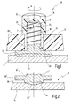
- Fig. 1 is a first embodiment of a fastening system of the present invention generally designated 10.
- the fastening system 10 serves to a body 12, in the illustrated Case a plastic part interspersed with an opening 13, on a component 14, in the present case, a body panel 14 to attach.
- the fastening system 10 includes a threaded bolt 16, the welded by stud welding on the body panel 16 is. Furthermore, the fastening system 10 includes a Fixing nut 18 made of plastic, on the threaded bolt 16 is screwed.
- the threaded bolt 16 includes a flange portion 20.
- Sub a flange should in the present case, a section be understood with a larger diameter, at least twice as large as the shank portion of the threaded bolt.
- the threaded bolt 16 is in the stud welding with the bottom its flange portion 20 on an upper side of the Body sheet 14 welded.
- the welded connection 22 is in Fig. 1 shown schematically.
- a shank portion 24 is provided, on which a coarse thread 26th is trained.
- the threaded bolt 16 also has a weakened Section 28, which in the present case is replaced by a Circumferential groove 30 is formed.
- the circumferential groove 30 provides a predetermined breaking point of the threaded bolt, as below in more detail will be explained.
- the fastening nut 18 has a bore 32 and the Diameter of the bore 32 is at the diameter of the shaft portion 24 adjusted.
- the coarse thread 26 is formed as a self-tapping thread and thus an internal thread is cut into the bore 32, when the fastening nut 18 on the threaded bolt 16 is screwed.
- Fig. 1 is indicated schematically as a to the fastening nut 18 applied torque M in the region of the thread 26 is converted into an axial force A, which has a tensile force causes the threaded bolt 16, and in a tangential force T, in turn, a corresponding moment on the threaded bolt 16 causes.
- FIG. 2 shows a modification 10 'of the fastening system 10 shown.
- the threaded bolt 16' with a flange portion 20 'formed between a Shank portion 24 'and a welding portion 34 is located.
- the diameter of the welding section 34 is chosen larger as the diameter of the shaft portion 24 '. Consequently lets a total of a welded joint 22 'with a strength Achieve greater than the strength that can be achieved is when the diameter of the welding portion 34 is equal to the - Prescribed - diameter of the shaft portion 24 'would be.
- the fastening system 10 For the rest, the fastening system 10 'does not differ from the fastening system 10 so that its description is referenced.
- Fig. 3 shows a further embodiment of a fastening system 40th
- the fastening system 40 serves to form a body 42 in shape a metal tube on a component 44 such as a body panel to fix.
- the fastening system 40 has a threaded bolt 46 which by means of a stud welding process on the body panel 44th is welded. Furthermore, the fastening system 40 includes a fastening nut 48 in the form of a plastic clip.
- the threaded bolt 46 has a flange portion 50 which the flange portion 20 'of the fastening system 10' of FIG. 2 equivalent.
- a welded joint between the threaded bolt 46 and the Body panel 14 is shown at 52.
- a shank portion 54 of the threaded bolt 46 is provided with a metric thread 56 provided.
- the threaded bolt 46 is in the region of the transition between the Shank portion 54 and the flange portion 50 weakened, such as it is shown schematically at 58.
- the weakening occurs at the fastening system 40 solely in that the diameter of the shank portion 54 is significantly smaller than the diameter the flange portion 50 and an unspecified, underlying welding section. Further, the transition between the shaft portion 54 and the flange portion 50 designed as a sharp-edged corner.
- the fastening nut 48 has a bore 60 which with a metric internal thread 62 is provided. Consequently lets the fastening nut 48 (the plastic clip) on the Screw on threaded bolt 46.
- the plastic clip on the threaded bolt 46 unscrewed until a bottom of the plastic clip 48 abuts on an upper side of the flange portion 50.
- the body 42 in the form of the metal tube is exclusively on set the plastic clip 48.
- the plastic clip 48 has a hinged mounted latching bracket 66, which is adapted to the Recess 64 to close and so the metal tube 42 positively in the plastic clip 48 record.
- fastening nuts 18, 48 from a material other than plastic can be made, provided that the below with reference to FIG. 4 Strength requirements are met.
- the body 12 may also be a metal element. Accordingly, the body 42 may also be a Act plastic element.
- a torque M is plotted on the abscissa, that in the illustration of FIG. 1 to the fastening nut 18th is applied to the body 12 to the body panel Fasten.
- the fastening nut 18 is screwed on with a certain nominal torque M N , which is qualitatively shown in FIG. 4 as greater than zero.
- the nominal torque M N is associated with a tolerance range T N within which the nominal torque M N typically applied by a torque wrench or driver varies.
- a predetermined breaking torque of the fastening nut 18 is further shown at M M.
- the predetermined breaking torque M M is qualitatively higher than the rated torque M N.
- the predetermined breaking moment M M is assigned a tolerance range T M , within which the fastening nut 18 breaks or its thread is destroyed.
- tolerance ranges T N and T M do not overlap, but preferably adjacent to each other.
- Fig. 4 also shows a predetermined breaking torque M G of the threaded bolt 16.
- the predetermined breaking torque M G is qualitatively higher than the predetermined breaking torque M M of the fastening nut 18.
- the predetermined breaking moment M G is assigned a tolerance range that does not overlap with the tolerance range T M of the fastening nut 18 , but immediately adjacent.
- the predetermined breaking torque M S is significantly greater than the predetermined breaking torque M G of the threaded bolt 16.
- the predetermined breaking torque M S of the welded joint 22 is also assigned a tolerance range T S.
- the tolerance range T S of the predetermined breaking torque M S of the welded joint 22 does not intersect with the tolerance range T G , but rather is considerably spaced therefrom. Consequently, it is ensured that the maximum of a threaded bolt still acceptable breaking load M G (the upper limit of the tolerance range T G ) is significantly smaller than the minimum predetermined breaking torque M S at which the weld joint 22 could break.
- FIG. 4 merely spoken of a fraction of the welded joint 22 Service. However, it goes without saying that this is a breach of the Welded joint and / or the body panel to be meant should.
- a glass fiber reinforced test nut is usually used. If, inadvertently, too high a torque is applied during this test, it is ensured by the spacing of the tolerance ranges T G and T S that in each case the threaded bolt 16 breaks and the welded connection 22 or the bodywork panel 14 are not damaged.
- Fig. 3 represents the plastic clip 48 is the fastening nut.
- the thread mating between the threaded bolt 16, 46 and the fastening nut 18, 48 to be selected should that when a destruction of the thread of the fastening nut 18, 48 a loosening should still be possible thus avoiding that when turning unnecessarily high torques be applied to the threaded bolt 16, 46.
- the fastening nut is 18, 48 (which is usually plastic) that "weakest link".
- the next weakest link is the fastening bolt 16.
- the greatest strength is the weld joint 22 or 52 on.
Landscapes
- Engineering & Computer Science (AREA)
- General Engineering & Computer Science (AREA)
- Mechanical Engineering (AREA)
- Physics & Mathematics (AREA)
- Plasma & Fusion (AREA)
- Connection Of Plates (AREA)
- Body Structure For Vehicles (AREA)
- Butt Welding And Welding Of Specific Article (AREA)
Description
- Fig. 1
- eine schematische Schnittansicht einer ersten Ausführungsform eines erfindungsgemäßen Befestigungssystems;
- Fig. 2
- eine Detailansicht einer abgewandelten Ausführungsform eines Befestigungssystems im Schnitt;
- Fig. 3
- eine Schnittdarstellung einer weiteren Ausführungsform des erfindungsgemäßen Befestigungssystems; und
- Fig. 4
- ein Diagramm mit einer qualitativen Darstellung verschiedener relevanter Drehmomente des Befestigungssystems der vorliegenden Erfindung.
Claims (9)
- Befestigungssystem (10; 40) zum Befestigen eines Körpers (12; 42) an einem metallischen Bauteil (14; 44), insbesondere zum Befestigen eines Körpers (12; 42) an einem Metallblech wie einem Karosserieblech (14; 44) eines Kraftfahrzeuges, mit einem metallischen Gewindebolzen (16; 46), der mittels Kurzzeit-Lichtbogenschweißen an dem Bauteil (14; 44) befestigt ist, und einer Befestigungsmutter (18; 48), die auf den Gewindebolzen (16; 46) geschraubt ist und mittels der der Körper (12; 42) an dem Bauteil (14; 44) befestigt ist,
dadurch gekennzeichnet, dass
die Festigkeit der Schweißverbindung (22; 52) zwischen dem Bauteil (14; 44) und dem Gewindebolzen (16; 46) und die Festigkeit des Gewindebolzens (16; 46) selbst so aufeinander abgestimmt sind, dass bei einem Aufbringen eines Drehmomentes (M) auf die Befestigungsmutter, das jenes Drehmoment (MN) übersteigt, das bestimmungsgemäß beim Aufschrauben der Befestigungsmutter (18; 48) auf den Gewindebolzen (16; 46) aufgebracht wird, gewährleistet ist, dass der Gewindebolzen (16; 46) bricht, bevor das Bauteil (14; 44) bricht. - Befestigungssystem (10; 40) zum Befestigen eines Körpers (12; 42) an einem metallischen Bauteil (14; 44), insbesondere zum Befestigen eines Körpers (12; 42) an einem Metallblech wie einem Karosserieblech (14; 44) eines Kraftfahrzeuges, mit einem metallischen Gewindebolzen (16; 46), der mittels Kurzzeit-Lichtbogenschweißen an dem Bauteil (14; 44) befestigt ist, und einer Befestigungsmutter (18; 48), die auf den Gewindebolzen (16; 46) geschraubt ist und mittels der der Körper (12; 42) an dem Bauteil (14; 44) befestigt ist,
dadurch gekennzeichnet, dass
die Festigkeit der Schweißverbindung (22; 52) zwischen dem Bauteil (14; 44) und dem Gewindebolzen (16; 46) und die Festigkeit des Gewindes des Gewindebolzens (16; 46) selbst so aufeinander abgestimmt sind, dass bei einem Aufbringen eines Drehmomentes (M) auf die Befestigungsmutter, das jenes Drehmoment (MN) übersteigt, das bestimmungsgemäß beim Aufschrauben der Befestigungsmutter (18; 48) auf den Gewindebolzen (16; 46) aufgebracht wird, gewährleistet ist, dass das Gewinde des Gewindebolzens (16; 46) beschädigt wird, bevor das Bauteil (14; 44) bricht. - Befestigungssystem nach Anspruch 1, dadurch gekennzeichnet, dass der Gewindebolzen (16; 46) an einer Stelle (28; 58) geschwächt ist und dass die Schwächung (28; 58) so ausgelegt ist, dass der Gewindebolzen (16; 46) an dem Ort der Schwächung (28; 58) bricht, bevor das Bauteil (14; 44) im Bereich der Schweißverbindung (22; 52) zwischen dem Bauteil (14; 44) und dem Gewindebolzen (16; 46) bricht.
- Befestigungssystem nach Anspruch 3, dadurch gekennzeichnet, dass der Gewindebolzen (16) eine schwächende Ausnehmung, insbesondere eine Umfangsnut (30) aufweist.
- Befestigungssystem nach einem der Ansprüche 1 - 4, dadurch gekennzeichnet, dass der Gewindebolzen (14; 46) einen Flanschabschnitt (20; 50) aufweist, der in der Nachbarschaft der Schweißverbindung (22; 52) angeordnet ist und gegen den der Körper (12) mittels der Befestigungsmutter (18) oder gegen den die Befestigungsmutter (48) selbst geschraubt ist.
- Befestigungssystem nach einem der Ansprüche 3 - 4 und nach Anspruch 5, dadurch gekennzeichnet, dass die geschwächte Stelle (28; 58) in der Nachbarschaft des Flanschabschnittes (20; 50) angeordnet ist.
- Befestigungssystem nach einem der Ansprüche 1 - 6, dadurch gekennzeichnet, dass der Gewindebolzen (16) ein Grobgewindebolzen (16) ist, dessen Außengewinde (26) beim Aufschrauben der Befestigungsmutter (18) ein Gewinde in deren Bohrung (32) schneidet.
- Befestigungssystem nach einem der Ansprüche 1 - 6, dadurch gekennzeichnet, dass der Gewindebolzen (46) ein Feingewinde wie ein metrisches Gewinde (56) aufweist und dass die Befestigungsmutter (48) ein entsprechendes Innengewinde (62) aufweist.
- Befestigungssystem nach einem der Ansprüche 1 - 8, dadurch gekennzeichnet, dass die Festigkeit des Gewindebolzens (16; 46) und die Festigkeit der Befestigungsmutter (18; 48) so aufeinander abgestimmt sind, dass bei einem Aufbringen eines Drehmomentes (M) auf die Befestigungsmutter (18; 48), das jenes Drehmoment (MN) übersteigt, das bestimmungsgemäß beim Aufschrauben der Befestigungsmutter (18; 48) auf den Gewindebolzen (16; 46) aufgebracht wird, gewährleistet ist, dass die Befestigungsmutter (18; 48) strukturell beschädigt wird, bevor der Gewindebolzen (16; 46) strukturell beschädigt wird.
Applications Claiming Priority (3)
| Application Number | Priority Date | Filing Date | Title |
|---|---|---|---|
| DE10156403A DE10156403C1 (de) | 2001-11-13 | 2001-11-13 | Befestigungssystem |
| DE10156403 | 2001-11-13 | ||
| PCT/EP2002/012468 WO2003042554A1 (de) | 2001-11-13 | 2002-11-08 | Befestigungssystem |
Publications (2)
| Publication Number | Publication Date |
|---|---|
| EP1444446A1 EP1444446A1 (de) | 2004-08-11 |
| EP1444446B1 true EP1444446B1 (de) | 2005-10-05 |
Family
ID=7706031
Family Applications (1)
| Application Number | Title | Priority Date | Filing Date |
|---|---|---|---|
| EP02781309A Expired - Lifetime EP1444446B1 (de) | 2001-11-13 | 2002-11-08 | Befestigungssystem |
Country Status (6)
| Country | Link |
|---|---|
| US (1) | US20050008427A1 (de) |
| EP (1) | EP1444446B1 (de) |
| JP (1) | JP2005509806A (de) |
| DE (2) | DE10156403C1 (de) |
| ES (1) | ES2249623T3 (de) |
| WO (1) | WO2003042554A1 (de) |
Families Citing this family (13)
| Publication number | Priority date | Publication date | Assignee | Title |
|---|---|---|---|---|
| BRPI0315125B1 (pt) * | 2002-10-07 | 2016-01-26 | Newfrey Llc | prendedor e construção de parafuso prisioneiro, método de acoplar uma haste rosqueada a uma estrutura e parafuso prisioneiro |
| JP4563067B2 (ja) * | 2004-04-14 | 2010-10-13 | メイラ株式会社 | タッピングねじ |
| DE102005014234B4 (de) * | 2005-03-30 | 2011-12-15 | Jürgen Franzke | Befestigungssystem mit wenigstens einem mit einem Trägerteil verbundenen Befestigungselement |
| US20070186740A1 (en) * | 2006-01-20 | 2007-08-16 | Steven Dreyer | Method and apparatus for forming and cutting vinyl tiles with rolled edges |
| DE102006028771A1 (de) * | 2006-06-23 | 2008-01-03 | Daimlerchrysler Ag | Hydrodynamischer Drehmomentwandler und Verfahren zur Herstellung eines solchen |
| US8641342B2 (en) * | 2008-07-09 | 2014-02-04 | Newfrey Llc | Stud for stud welding |
| JP2010017740A (ja) * | 2008-07-10 | 2010-01-28 | Nippon Stud Welding Co Ltd | スタッドボルト |
| US20140109415A1 (en) * | 2012-10-19 | 2014-04-24 | Hantover, Inc. | Breakaway lug drive coupler of rotary knife |
| CN103170775A (zh) * | 2013-03-20 | 2013-06-26 | 大连奥托自动化设备有限公司 | 手持导向机构 |
| US9803678B2 (en) | 2014-08-11 | 2017-10-31 | Akko Fastener Inc. | Arc weld stud having a forming thread |
| CN111188824A (zh) * | 2019-12-31 | 2020-05-22 | 上海球明标准件有限公司 | 一种用在车身钣金件上的高连接稳固性焊接螺母 |
| KR102400274B1 (ko) * | 2020-12-17 | 2022-05-20 | 주식회사 성우하이텍 | 접합 하드웨어를 이용한 이종소재의 접합방법 |
| DE102022111091B4 (de) | 2022-05-05 | 2025-12-31 | Dr. Ing. H.C. F. Porsche Aktiengesellschaft | Verfahren zum Trennen von mindestens zwei zusammengehaltenen Komponenten und Befestigungssystem |
Family Cites Families (20)
| Publication number | Priority date | Publication date | Assignee | Title |
|---|---|---|---|---|
| US2983181A (en) * | 1957-11-12 | 1961-05-09 | Nelson Stud Welding Division O | Sheet fastener |
| GB1096812A (en) * | 1963-08-13 | 1967-12-29 | Kenneth Ernest Stanley | A fastening stud |
| US4595324A (en) * | 1982-09-28 | 1986-06-17 | Monogram Industries, Inc. | Impulse resistant blind fastener |
| US4850771A (en) * | 1986-04-01 | 1989-07-25 | Hurd Ramon L | Installation system for securing workpieces of composite materials and the like and threaded fastener for such system |
| DE3618902A1 (de) * | 1986-04-21 | 1987-12-10 | Tucker Gmbh | Schweissbolzen mit hutmutter |
| DE3802798A1 (de) * | 1988-01-30 | 1989-08-10 | Baeurle Ulrich | Verfahren und vorrichtung zum verbinden von bauelementen insbesondere von pfetten und wandriegeln |
| US5171115A (en) * | 1991-11-05 | 1992-12-15 | Huck International, Inc. | Swage collar with pintail and fastening system and method |
| US5199834A (en) * | 1992-01-14 | 1993-04-06 | Textron Inc. | Air bag stud |
| US5442133A (en) * | 1993-09-08 | 1995-08-15 | Emhart Inc. | Grounding stud/nut |
| GB2283293A (en) * | 1993-10-29 | 1995-05-03 | Avdel Systems Ltd | Dual-function fastener and method of use |
| JPH07223078A (ja) * | 1994-02-15 | 1995-08-22 | Yoshitaka Aoyama | ボルトのプロジェクション溶接方法 |
| AT401805B (de) * | 1994-03-14 | 1996-12-27 | Mark Rudolf | Befestigungsmutter, insbesondere für eine verbindungsanordnung |
| US5472228A (en) * | 1994-08-05 | 1995-12-05 | Morton International, Inc. | Break-away fastening system for air bag deployment doors |
| US5613701A (en) * | 1995-05-16 | 1997-03-25 | Morton International Inc. | Break-away fastening system for air bag deployment doors |
| US5618123A (en) * | 1995-08-11 | 1997-04-08 | Pettibone Corporation | Coupling device for sewer and drain cleaning cable |
| DE10004720C1 (de) * | 2000-02-03 | 2001-08-16 | Bayerische Motoren Werke Ag | Vorrichtung und Verfahren zum Prüfen der Befestigungsstelle eines ein Außengewinde aufweisenden Bolzens auf Torsionsfestigkeit |
| DE10014078C5 (de) * | 2000-03-22 | 2007-04-05 | Nelson Bolzenschweiß-Technik GmbH & Co. KG | Verfahren zur Herstellung eines Schweißbolzens |
| US6565125B2 (en) * | 2000-04-27 | 2003-05-20 | Perfection Corporation | Coupling assembly for joining plastic and metal pipes |
| US7059022B2 (en) * | 2001-09-03 | 2006-06-13 | Newfrey Llc | Spacer for attaching a dash silencer |
| BRPI0315125B1 (pt) * | 2002-10-07 | 2016-01-26 | Newfrey Llc | prendedor e construção de parafuso prisioneiro, método de acoplar uma haste rosqueada a uma estrutura e parafuso prisioneiro |
-
2001
- 2001-11-13 DE DE10156403A patent/DE10156403C1/de not_active Expired - Lifetime
-
2002
- 2002-11-08 JP JP2003544351A patent/JP2005509806A/ja active Pending
- 2002-11-08 EP EP02781309A patent/EP1444446B1/de not_active Expired - Lifetime
- 2002-11-08 WO PCT/EP2002/012468 patent/WO2003042554A1/de not_active Ceased
- 2002-11-08 DE DE50204491T patent/DE50204491D1/de not_active Expired - Fee Related
- 2002-11-08 ES ES02781309T patent/ES2249623T3/es not_active Expired - Lifetime
-
2004
- 2004-05-13 US US10/850,565 patent/US20050008427A1/en not_active Abandoned
Also Published As
| Publication number | Publication date |
|---|---|
| WO2003042554A1 (de) | 2003-05-22 |
| US20050008427A1 (en) | 2005-01-13 |
| DE50204491D1 (de) | 2006-02-16 |
| JP2005509806A (ja) | 2005-04-14 |
| EP1444446A1 (de) | 2004-08-11 |
| DE10156403C1 (de) | 2003-04-17 |
| ES2249623T3 (es) | 2006-04-01 |
Similar Documents
| Publication | Publication Date | Title |
|---|---|---|
| EP1674741B1 (de) | Ein durch Nieten an ein Blechteil anbringbares Element sowie Zusammenbauteil und Verfahren zur Erzeugung des Zusammenbauteils | |
| DE60129153T2 (de) | Verbindungskonstruktion und verfahren zur herstellung einer verbindungskonstruktion | |
| DE10156403C1 (de) | Befestigungssystem | |
| DE102014204449A1 (de) | Verfahren zum Verbinden von Bauteilen von denen eines aus einem faserverstärkten Kunststoff besteht | |
| EP0678679A1 (de) | Ein durch Nieten in ein Blechteil einsetzbares Element | |
| WO2003002879A2 (de) | Selbstbohrende blindnietmutter | |
| EP1360744A1 (de) | Befestigung für einen elektrischen kontakt | |
| DE19821160C1 (de) | Befestigungssystem | |
| DE202008017727U1 (de) | Bolzen für das Bolzenschweißen | |
| DE19516425B4 (de) | Einrichtung zur lösbaren Befestigung einer Achse | |
| DE19821646A1 (de) | Befestigungssystem | |
| AT401805B (de) | Befestigungsmutter, insbesondere für eine verbindungsanordnung | |
| DE102013002631B4 (de) | Bauteilverbindung für ein Anbauteil an einem Trägerteil | |
| DE19949161B4 (de) | Befestigungsanordnung zum Befestigen eines Nietelementes an einem plattenförmigen Bauteil | |
| EP1612432B1 (de) | Befestigungsanordnung für eine Verkleidung und Befestigungsverfahren | |
| EP0595041A2 (de) | Befestigung, insbesondere an nur einseitig zugänglichen Durchgangsbohrungen | |
| DE3905175C1 (en) | Pipe clamp for hydraulic pipes | |
| DE3510300A1 (de) | Befestigungsschraube, insbesondere fuer stossfaenger von kraftfahrzeugen | |
| DE202005015713U1 (de) | Selbststanzender Befestiger und Vorrichtung zum Verbinden des selbststanzenden Befestigers mit einem Kunststoffteil | |
| DE102019107713A1 (de) | Fahrwerkbauteil und Verfahren zur Herstellung eines Fahrwerkbauteils | |
| DE102019203368B4 (de) | Schutzrohr für einen Schwingungsdämpfer, Schwingungsdämpfer für eine Kraftfahrzeugradaufhängung mit einem Schutzrohr und Verfahren zur Montage eines Schutzrohrs | |
| DE102009008220A1 (de) | Befestigungselement für die strukturversteifte Befestigung eines Kraftfahrzeugbauteils | |
| DE102022111091B4 (de) | Verfahren zum Trennen von mindestens zwei zusammengehaltenen Komponenten und Befestigungssystem | |
| DE102005028092A1 (de) | Haltereinheit zur Befestigung von Anbauteilen an einem Fahrzeugrahmen | |
| DE29919502U1 (de) | Blindniet |
Legal Events
| Date | Code | Title | Description |
|---|---|---|---|
| PUAI | Public reference made under article 153(3) epc to a published international application that has entered the european phase |
Free format text: ORIGINAL CODE: 0009012 |
|
| 17P | Request for examination filed |
Effective date: 20040505 |
|
| AK | Designated contracting states |
Kind code of ref document: A1 Designated state(s): AT BE BG CH CY CZ DE DK EE ES FI FR GB GR IE IT LI LU MC NL PT SE SK TR |
|
| GRAP | Despatch of communication of intention to grant a patent |
Free format text: ORIGINAL CODE: EPIDOSNIGR1 |
|
| GRAS | Grant fee paid |
Free format text: ORIGINAL CODE: EPIDOSNIGR3 |
|
| GRAA | (expected) grant |
Free format text: ORIGINAL CODE: 0009210 |
|
| RIN1 | Information on inventor provided before grant (corrected) |
Inventor name: DREXLER, FRANK Inventor name: PFUNDTNER, FRANZ Inventor name: SCHNEIDER, JOACHIM Inventor name: HUBER, HUBERT |
|
| AK | Designated contracting states |
Kind code of ref document: B1 Designated state(s): DE ES FR GB IT |
|
| REG | Reference to a national code |
Ref country code: GB Ref legal event code: FG4D Free format text: NOT ENGLISH |
|
| GBT | Gb: translation of ep patent filed (gb section 77(6)(a)/1977) |
Effective date: 20051007 |
|
| PGFP | Annual fee paid to national office [announced via postgrant information from national office to epo] |
Ref country code: FR Payment date: 20051117 Year of fee payment: 4 |
|
| PGFP | Annual fee paid to national office [announced via postgrant information from national office to epo] |
Ref country code: ES Payment date: 20051124 Year of fee payment: 4 |
|
| PGFP | Annual fee paid to national office [announced via postgrant information from national office to epo] |
Ref country code: DE Payment date: 20060102 Year of fee payment: 4 |
|
| REF | Corresponds to: |
Ref document number: 50204491 Country of ref document: DE Date of ref document: 20060216 Kind code of ref document: P |
|
| REG | Reference to a national code |
Ref country code: ES Ref legal event code: FG2A Ref document number: 2249623 Country of ref document: ES Kind code of ref document: T3 |
|
| ET | Fr: translation filed | ||
| PLBE | No opposition filed within time limit |
Free format text: ORIGINAL CODE: 0009261 |
|
| STAA | Information on the status of an ep patent application or granted ep patent |
Free format text: STATUS: NO OPPOSITION FILED WITHIN TIME LIMIT |
|
| 26N | No opposition filed |
Effective date: 20060706 |
|
| PGFP | Annual fee paid to national office [announced via postgrant information from national office to epo] |
Ref country code: IT Payment date: 20061130 Year of fee payment: 5 |
|
| PG25 | Lapsed in a contracting state [announced via postgrant information from national office to epo] |
Ref country code: DE Free format text: LAPSE BECAUSE OF NON-PAYMENT OF DUE FEES Effective date: 20070601 |
|
| GBPC | Gb: european patent ceased through non-payment of renewal fee |
Effective date: 20061108 |
|
| REG | Reference to a national code |
Ref country code: FR Ref legal event code: ST Effective date: 20070731 |
|
| PG25 | Lapsed in a contracting state [announced via postgrant information from national office to epo] |
Ref country code: GB Free format text: LAPSE BECAUSE OF NON-PAYMENT OF DUE FEES Effective date: 20061108 |
|
| REG | Reference to a national code |
Ref country code: ES Ref legal event code: FD2A Effective date: 20061110 |
|
| PG25 | Lapsed in a contracting state [announced via postgrant information from national office to epo] |
Ref country code: FR Free format text: LAPSE BECAUSE OF NON-PAYMENT OF DUE FEES Effective date: 20061130 Ref country code: ES Free format text: LAPSE BECAUSE OF NON-PAYMENT OF DUE FEES Effective date: 20061110 |
|
| PG25 | Lapsed in a contracting state [announced via postgrant information from national office to epo] |
Ref country code: IT Free format text: LAPSE BECAUSE OF NON-PAYMENT OF DUE FEES Effective date: 20071108 |