EP1444428B1 - Procede et dispositif pour prevenir le pompage dans une turbine a gaz - Google Patents
Procede et dispositif pour prevenir le pompage dans une turbine a gaz Download PDFInfo
- Publication number
- EP1444428B1 EP1444428B1 EP02789692A EP02789692A EP1444428B1 EP 1444428 B1 EP1444428 B1 EP 1444428B1 EP 02789692 A EP02789692 A EP 02789692A EP 02789692 A EP02789692 A EP 02789692A EP 1444428 B1 EP1444428 B1 EP 1444428B1
- Authority
- EP
- European Patent Office
- Prior art keywords
- engine
- schedule
- surge
- pressure compressor
- low pressure
- Prior art date
- Legal status (The legal status is an assumption and is not a legal conclusion. Google has not performed a legal analysis and makes no representation as to the accuracy of the status listed.)
- Expired - Lifetime
Links
Images


Classifications
-
- F—MECHANICAL ENGINEERING; LIGHTING; HEATING; WEAPONS; BLASTING
- F02—COMBUSTION ENGINES; HOT-GAS OR COMBUSTION-PRODUCT ENGINE PLANTS
- F02C—GAS-TURBINE PLANTS; AIR INTAKES FOR JET-PROPULSION PLANTS; CONTROLLING FUEL SUPPLY IN AIR-BREATHING JET-PROPULSION PLANTS
- F02C9/00—Controlling gas-turbine plants; Controlling fuel supply in air- breathing jet-propulsion plants
- F02C9/26—Control of fuel supply
- F02C9/28—Regulating systems responsive to plant or ambient parameters, e.g. temperature, pressure, rotor speed
-
- F—MECHANICAL ENGINEERING; LIGHTING; HEATING; WEAPONS; BLASTING
- F02—COMBUSTION ENGINES; HOT-GAS OR COMBUSTION-PRODUCT ENGINE PLANTS
- F02C—GAS-TURBINE PLANTS; AIR INTAKES FOR JET-PROPULSION PLANTS; CONTROLLING FUEL SUPPLY IN AIR-BREATHING JET-PROPULSION PLANTS
- F02C9/00—Controlling gas-turbine plants; Controlling fuel supply in air- breathing jet-propulsion plants
- F02C9/48—Control of fuel supply conjointly with another control of the plant
- F02C9/50—Control of fuel supply conjointly with another control of the plant with control of working fluid flow
- F02C9/52—Control of fuel supply conjointly with another control of the plant with control of working fluid flow by bleeding or by-passing the working fluid
-
- F—MECHANICAL ENGINEERING; LIGHTING; HEATING; WEAPONS; BLASTING
- F05—INDEXING SCHEMES RELATING TO ENGINES OR PUMPS IN VARIOUS SUBCLASSES OF CLASSES F01-F04
- F05D—INDEXING SCHEME FOR ASPECTS RELATING TO NON-POSITIVE-DISPLACEMENT MACHINES OR ENGINES, GAS-TURBINES OR JET-PROPULSION PLANTS
- F05D2270/00—Control
- F05D2270/01—Purpose of the control system
- F05D2270/10—Purpose of the control system to cope with, or avoid, compressor flow instabilities
- F05D2270/101—Compressor surge or stall
Definitions
- the subject disclosure relates a control system for use with gas turbine engines, and more particularly, to a control system for helicopters which includes a system for preventing engine surge events by adapting acceleration schedules stored in the aircraft computer's non-volatile memory.
- An engine surge is generally regarded as a mismatch between the speed of the compressor blades and the incoming air.
- An engine surge is typically a precursor to an engine stall event.
- Engine surges are characterized by a sudden and large loss of power, a loss of air flow, an increase in temperature and mechanical vibration. These mechanical vibrations, as well as the temperature increases, impose substantial stress on the engine and particularly on the turbine blades. While also occurring under other operating conditions, an engine surge event will most often occur during acceleration.
- the acceleration schedule is traditionally provided by the engine manufacturer and is developed over time.
- the schedule protects the engine from surge, stall and overtemperature by regulating the fuel flow.
- the acceleration schedule is a function of the engine operating characteristics, and therefore, it is specific or unique to a particular engine model.
- the schedule typically represents the demanded rate of change of the gas generator speed (NDOT Demand ) as a function of measured gas generator speed (NG) and engine inlet air temperature and pressure.
- NDOT Demand the demanded rate of change of the gas generator speed
- NG measured gas generator speed
- the schedule is not linear, but of complex shape. The complexity of the schedule is partly due to the need to prevent the engine from operating in the compressor stall region.
- prior art fuel controls have been pre-programmed with an acceleration schedule and, in theory, if fuel flow is maintained in accordance with the requirements of the schedule, the engine is accelerated without surge. It is to be noted that, if an excess of fuel is delivered to the engine during surge, the engine is likely to stay in the surge condition or experience multiple surges. Therefore, prior art control systems will typically include a safety factor which is known as the surge margin. The surge margin will be taken into account in deriving the acceleration schedule and the engine will be capable of accepting a predetermined percentage of additional fuel flow before surge will occur.
- Engine controls are designed and implemented for the operating characteristics of a new engine.
- the characteristics of an engine and/or its fuel metering system will vary over time as the equipment ages. Accordingly, what may have initially been an adequate acceleration schedule and/or surge margin may, with engine and/or fuel control deterioration, no longer ensure that the engine will not surge.
- the modifier which corresponds to the point on the acceleration schedule where the surge was experienced will be decremented by a preselected percentage.
- the fuel flow related information from the acceleration schedule is multiplied by the modifier with the result that, subsequent to a surge having been detected, future accelerations will be modified within a small corrected speed band surrounding the surge point.
- a gas turbine engine which includes a compressor joined to a turbine by a core rotor and a combustor disposed therebetween.
- a speed sensor measures the speed of the core rotor, and a pressure sensor measures pressure at an inlet to the compressor.
- a controller which is operatively joined to the sensors and a fuel valve providing fuel to the combustor limits the fuel flow to the combustor in response to the acceleration rate of the core rotor and the inlet pressure of the inlet air entering the compressor so as to limit transient temperature of the combustion gas discharged from the combustor into the turbine.
- the invention provides a method of and a system for preventing surge events in a gas turbine engine and is characterized by the features of claims 1 and 9, respectively.
- the disclosure of the present invention relates to an engine surge avoidance system and method which adapts the acceleration schedules stored in the aircraft computer's non-volatile memory to prevent engine surge events from occurring while minimizing reductions in engine response time.
- the surge avoidance system and method disclosed herein achieves this goal by adapting both the NDOT and the intercompressor (P 2.5 ) bleed schedules in an optimum fashion.
- the gas turbine engine typically includes, in serial flow communication, a low pressure compressor, a high pressure compressor, a combustor, a high pressure turbine and a low pressure turbine.
- the method includes establishing a transient temperature limit for the gas turbine engine and estimating the combustor discharge gas temperature. Then, the combustor discharge gas temperature is compared to the established transient temperature limit. If the estimated combustor discharge gas temperature is less than the established transient temperature limit, the low pressure compressor bleed air flow rate schedule is modified so as to improve an engine surge avoidance margin. Alternatively, if the estimated combustor discharge gas temperature is greater than the established transient temperature limit, the engine fuel flow rate schedule is modified so as to improve the engine surge avoidance margin.
- the method disclosed herein may further include the step of measuring the combustor discharge gas temperature with a sensing means operatively positioned on the engine housing.
- the method may further include measuring a plurality of engine operating parameters and estimating the combustor discharge gas temperature using a thermodynamic engine model and the plurality of measured engine operating parameters.
- the plurality of operating parameters can include, but are not limited to, parameters such as component operating temperature, component inlet and exhaust air/gas temperatures or pressures, shaft, bearing speed or gear rotational speed, and engine shaft torque.
- the engine model is adaptive can be used to estimate component efficiencies and unknown operating parameters based on the measured operating parameters.
- the maximum allowable modification to the fuel flow schedule is established and a determination is made as to whether the maximum allowable modification to the fuel flow schedule has been reached. If the maximum has been reached, the low pressure compressor bleed air flow rate schedule are modified so as to improve the engine surge margin.
- the step of modifying an engine fuel flow rate schedule if the predicted combustor discharge gas temperature is greater than the established transient temperature limit includes estimating a core shaft speed for the engine.
- the low pressure compressor bleed air flow rate schedule defines a bleed valve position over an entire range of low pressure compressor shaft speeds.
- the fuel flow rate schedule defines an acceleration rate for the engine's core shaft over an entire range of engine core shaft speeds.
- the acceleration rate and core shaft speed for the engine are corrected by temperature of low pressure compressor inlet air.
- the present disclosure is also directed to a system for preventing surge events in a gas turbine engine following an initial surge event.
- the gas turbine engine preferably includes in serial flow communication a low pressure compressor, a high pressure compressor, a combustor, a high pressure turbine and a low pressure turbine.
- a representative system includes a mechanism for establishing a transient temperature limit for a gas turbine engine, a mechanism for estimating a combustor discharge gas temperature and a device for comparing the estimated combustor discharge gas temperature to the established transient temperature limit. If the estimated combustor discharge gas temperature is less than the established transient temperature limit the system includes a mechanism for modifying the low pressure compressor bleed air flow rate schedule stored in non-volatile computer memory so as to improve an engine surge avoidance margin. If the estimated combustor discharge gas temperature is greater than the established transient temperature limit, the system includes a component for modifying an engine fuel flow rate schedule stored in non-volatile computer memory limit so as to improve the engine surge avoidance margin.
- system further includes a sensor operatively positioned on the engine housing.
- system includes a mechanism for measuring a plurality of engine operating parameters and estimating based on the measured parameters the combustor discharge gas temperature using a thermodynamic engine model.
- Fig. 1 a schematic representation of an exemplary aircraft gas turbine engine 10.
- the engine 10 includes, in serial flow communication, a plurality of conventional components including a low pressure compressor 12, a high pressure compressor 14, and an annular combustor 16.
- the engine 10 further includes a high pressure turbine 18, which may be a single stage for example, a low pressure turbine 20, which may also be a single stage, for example, an afterburner or augmenter 22 including separate fuel injectors (not shown), and a cooperating variable area exhaust nozzle 24.
- the low pressure compressor 12, high pressure compressor 14, high pressure turbine 18, and low pressure turbine 20 each include respective rows of circumferentially spaced apart rotor blades and cooperating stator vanes or nozzles in a conventional configuration.
- the high pressure turbine 18 is fixedly joined to the high pressure compressor 14 by a core shaft or rotor 26.
- the low pressure turbine 20 is fixedly joined to the low pressure compressor 12 by a corresponding low pressure compressor shaft or rotor 28.
- a plurality of conventional fuel injectors 30 are mounted around the upstream inlet end of the combustor 16 and are disposed in flow communication with a conventional fuel control valve 32.
- the valve 32 is suitably joined to a fuel tank 34 which contains fuel 34a which is suitably pressurized and provided to the valve 32 for metered flow therethrough to the injectors 30.
- the engine 10 also includes a digitally programmable controller 36 which may take any conventional form, and is suitably electrically joined to the fuel valve 32 for controlling operation thereof and metering the fuel flow, designated W f , into the combustor 16.
- a digitally programmable controller 36 which may take any conventional form, and is suitably electrically joined to the fuel valve 32 for controlling operation thereof and metering the fuel flow, designated W f , into the combustor 16.
- air indicated by flow lines 38 enters the low pressure compressor 12 and is pressurized through the high pressure compressor 14, mixed with the fuel 34a in the combustor 16 and suitably ignited for generating hot combustion gas indicated by flow lines 40.
- the combustion gas 40 is discharged from the combustor 16 and enters the high pressure turbine 18, which extracts energy therefrom for powering the high pressure compressor 14.
- the combustion gas 40 in turn flows downstream through the low pressure turbine 20 which extracts additional energy therefrom for powering the low pressure compressor 12.
- additional fuel may be introduced and ignited in the afterburner 22 for augmenting thrust from the engine 10, with the variable area exhaust nozzle 24 being suitably operatively joined to the controller 36 for varying the exhaust area thereof for use in controlling the engine 10 in a conventional manner.
- engine 10 includes a conventional core shaft speed sensor 42 adjoining the core rotor 26 at any convenient location, such as at the radially outer tips of the rotor blades of the high pressure compressor 14, for measuring rotational speed (NG), of the core rotor 26 during operation.
- the speed sensor 42 provides a suitable electrical signal representative ofNG for use in the controller 36.
- the core speed NG is an actual speed, and it is conventional to correct the speed in the controller 36 for use in controlling the engine.
- Corrected core speed NGc is typically accomplished by using a temperature sensor 44 suitably mounted between the low pressure compressor 12 and the compressor 14 for measuring the temperature of the air 38 entering the high pressure compressor 14 and providing a corresponding electrical signal to the controller 36.
- Core speed NG is typically corrected by dividing the measured value by the square root of the compressor inlet absolute temperature, normalized by standard day temperature.
- a sensor 43 can also be used to measure the speed of the low pressure compressor (NL), and the signal can be corrected within controller 36 to account for the operating temperature.
- a surge is generally regarded as a mismatch between the speed of the compressor blades and the incoming engine air and is a precursor to engine stall.
- Various techniques have been developed for sensing the occurrence of a stall condition in a gas turbine engine.
- a mild stall is indicated by one or more of the following: abnormal engine noise, rapid exhaust gas temperature fluctuations, RPM fluctuations, engine pressure ratio decrease or fluctuation, vibration due to compressor pulsation, or poor engine response to power level movements.
- a severe stall can be indicated by loud engine noises, flame, vapor, or smoke at the engine inlet and/or exhaust, and may be accompanied by engine malfunction or failure (see, for example, " Aircraft Gas Turbine Engine Technology", 2nd Edition, 1979, I.E. Treager, Mcgraw-Hill, Inc., pgs. 123-126 ).
- Previous techniques that are known for detecting an engine surge include a technique which compares engine control parameters with actual engine parameters.
- the existence of a sustained difference between a rate of change in engine speed, that is demanded (NDOT demanded ) by an engine control and the actual rate of change in engine speed (NDOT actual ) may indicate a surge condition.
- Another technique uses an engine signature to detect an engine surge, and relies primarily on a measurement of combustor burner pressure. In particular, this technique relies on sensing a transient spike in the combustor burner pressure.
- a third, and generally more complex technique employs a large number of engine and airframe parameters which are individually weighted and compensated.
- a system and method for detecting a surge event is not the subject of the present application, however, an exemplary embodiment of the surge avoidance system of the present invention receives a signal from a surge detection system (SDS) prior to implementing the surge avoidance logic disclosed herein.
- the output of the SDS is a surge flag (SRGFLG) signal.
- the SRGFLG signal is employed as an input to the subject control system or surge avoidance system for use in adapting the stored acceleration schedules so as to avoid the occurrence of, or recover from, an engine stall.
- the SRGFLG signal may also be employed to provide an audio and/or visual surge indicator to a pilot.
- surge avoidance system 100 modifies (i.e., decrements) the engine acceleration schedule following a surge event in order to avoid future surges.
- the decrement magnitudes are set at zero.
- the surge detection system (not shown) determines that a surge has occurred, the SURGE_FLAG transitions from 0 to 1.
- the surge avoidance logic 110 decrements at 3 points the surge avoidance modifier 120.
- the modifier 120 is decremented by 20% at the point closest to the corrected gas generator shaft speed corresponding to the surge event (NGc_surge) and 10% at the opposed points adjacent to NGc_surge.
- Surge avoidance logic 110 resets all of the points in the modifier to 1.0 (i.e., decrement magnitudes to zero) at power-up. It should be noted that surge avoidance modifier 120 has a lower limit of 0.5 or 50%.
- the modifier 120 is applied to the acceleration schedule and the engine control system adjusts the fuel flow accordingly. Although this system prevents surge events from recurring, it does so with little regard for the slow engine response which results from the adaptation.
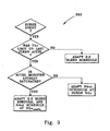
- Fig. 3 there is illustrated a flow chart for the surge avoidance method of the present disclosure which is designated generally by reference numeral 200.
- the transient temperature of the combustor discharge gas T 4.0 is compared to a pre-established temperature limit.
- the temperature of the combustor discharge gas T 4.0 can be sensed directly using a temperature sensor operatively positioned on the engine housing or T 4.0 can be predicted/estimated using, for example, an adaptive engine model.
- the predicted T 4.0 will change based on changes in the component efficiencies over time caused by wear.
- Fig. 6 provides a graphical representation of the change in T 4.0 and the steady state horsepower resulting from a 2% degradation in both the low pressure compressor and high pressure turbine efficiencies. It should be noted that the pre-established transient temperature limit would be established by the engine manufacturer and would be unique to each engine design. However, the transient temperature limit can be adjusted based on operational data and experience.
- the compressor inlet air bleed valve schedule is adapted to increase/schedule more transient bleed air.
- the addition of transient bleed air prevents engine surge events by increasing the transient surge margin without adversely impacting engine response time. Transient temperatures do increase somewhat as a result of the scheduling of more transient bleed air, but the engine still operates below its temperature limit.
- the only recourse is to adapt the NDOT acceleration schedule because of the temperature increase associated with scheduling more transient bleed air.
- the modifier it is preferable to review the modifier to determine if the lower limit has been reached (i.e., if it is saturated). If the lower limit has not been reached, the NDOT schedule is adapted.
- the schedule can be adapted as previously disclosed or by using any known adaptation technique, for example, the technique disclosed in U.S. Patent No. 4,490,791 to Morrison . Lowering the NDOT also prevents engine surge events, but at the expense of a slower response time.
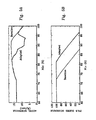
- FIGs. 5a and 5b provide comparisons of the baseline versus the adapted schedules for NDOT and P 2.5 , respectively.
- the approach disclosed herein optimally adjusts NDOT and P 2.5 bleed schedules to provide both transient surge and temperature margin.
- the amount of adaptation of the P 2.5 bleed schedule can also be predetermined based on engine performance testing and can be adjusted based on operational experience.
- Fig. 5b provides a illustration of an adapted P 2.5 bleed valve schedule. The graphical representation provided therein illustrates that the adaptation shifts the schedule to the right such that more bleed valve air is provided when the corrected low pressure compressor speed is in excess of about 73% of the corrected low pressure compressor speed (NLc).
- FIG. 4 there is depicted a schematic representation of a control system of the present disclosure which adapts either the P 2.5 bleed valve schedule or the NDOT acceleration schedule based on the surge avoidance method 200 described in Fig. 3 .
- a signal representing NGc is provided to the schedule representing NDOT demanded vs. NGc to determine NDOT demanded .
- Two curves are provided on the schedule, the first representing the combat operation configuration, and the second representing the normal operation mode.
- Signals representing the NDOT combat or NDOT normal are provided to summing junction 210.
- the magnitude of NDOT normal is subtracted from NDOT combat and an output signal representing the resultant is provided to multiplier logic 220.
- a signal representing NGc is also provided to the surge avoidance modifier 230, which has been decremented as directed by surge avoidance method 200.
- a signal representing the modifier which correlates to the NGc is provided to multiplier logic 220.
- the output of multiplier logic 220 is provided to summing junction 240 and added to NDOT normal .
- the resulting value is provided to the fuel control system (not shown) so as to regulate the fuel flow to the combustor.
- a signal representing NLc is provided to bleed valve schedule 250 which provides as an output the commanded bleed valve position.
Claims (16)
- Procédé destiné à empêcher le pompage dans une turbine à gaz par suite d'un pompage initial, le procédé étant caractérisé par les étapes consistant à :a) établir une limite de température transitoire pour la turbine à gaz ;b) estimer une température de gaz de décharge de la chambre de combustion ;c) comparer la température de gaz de décharge de la chambre de combustion estimée à la limite de température transitoire établie ;d) modifier un programme de débit d'air de prélèvement de compresseur basse pression stocké dans une mémoire non volatile si la température du gaz de décharge de la chambre de combustion estimée est inférieure à la limite de température transitoire établie de manière à améliorer une marge d'évitement de pompage du moteur ; ete) modifier un programme de débit de combustible du moteur stocké dans une mémoire non volatile si la température du gaz de décharge de la chambre de combustion estimée est supérieure à la limite de température transitoire établie de manière à améliorer la marge d'évitement de pompage du moteur.
- Procédé selon la revendication 1, comprenant en outre l'étape consistant à mesurer la température de gaz de décharge de la chambre de combustion avec des moyens de détection positionnés de manière opérationnelle sur le carter du moteur.
- Procédé selon la revendication 1, comprenant en outre les étapes consistant à :a) mesurer une pluralité de paramètres de fonctionnement du moteur ; etb) estimer la température du gaz de décharge de la chambre de combustion en utilisant un modèle de moteur thermodynamique et la pluralité de paramètres de fonctionnement du moteur mesurés.
- Procédé selon la revendication 1, dans lequel avant de modifier un programme d'écoulement de combustible du moteur si la température du gaz de décharge de la chambre de combustion estimée est supérieure à la limite de température transitoire établie, le procédé comprend en outre les étapes consistant à :a) établir une modification admissible maximale par rapport au programme d'écoulement de combustible ;b) déterminer si la modification admissible maximale par rapport au programme d'écoulement du combustible a été atteinte ; etc) modifier le programme de débit d'air de prélèvement de compresseur basse pression de manière à améliorer la marge de pompage du moteur si la modification admissible maximale par rapport au programme d'écoulement de combustible a été atteinte.
- Procédé selon la revendication 1, dans lequel l'étape consistant à modifier un programme de débit de combustible du moteur si la température du gaz de décharge de la chambre de combustion prévue est supérieure à la limite de température transitoire établie comprend l'étape consistant à estimer la vitesse du compresseur haute pression du moteur.
- Procédé selon la revendication 1, dans lequel le programme de débit d'air de prélèvement du compresseur basse pression définit une position de soupape de prélèvement sur une plage totale de vitesses d'arbre du compresseur basse pression.
- Procédé selon la revendication 1, dans lequel le programme de débit de combustible définit un taux d'accélération pour l'arbre interne du moteur sur une plage totale de vitesses de l'arbre interne du moteur.
- Procédé selon la revendication 7, dans lequel le taux d'accélération et la vitesse de l'arbre interne pour le moteur sont corrigés par la température de l'air admis du compresseur basse pression.
- Système destiné à empêcher un pompage par suite d'un pompage initial dans une turbine à gaz (10) qui comporte en communication fluidique sérielle un compresseur basse pression (12), un compresseur haute pression (14), une chambre de combustion (16), une turbine haute pression (18) et une turbine basse pression (20), le système pouvant être raccordé à la turbine à gaz (10) et comprenant :des moyens destinés à établir une limite de température transitoire pour une turbine à gaz ; etdes moyens destinés à modifier l'écoulement de combustible du moteur en fonction de la limite de température transitoire établie,le système étant caractérisé pardes moyens destinés à estimer une température du gaz de décharge de la chambre de combustion ;des moyens destinés à comparer la température du gaz de décharge de la chambre de combustion estimée à la limite de température transitoire établie ; etdes moyens destinés à modifier un programme de débit d'air de prélèvement de compresseur basse pression stocké dans une mémoire non volatile si la température du gaz de décharge de la chambre de combustion estimée est inférieure à la limite de température transitoire établie de manière à améliorer une marge d'évitement de pompage du moteur,dans lequel lesdits moyens destinés à modifier l'écoulement de combustible du moteur comprennent des moyens destinés à modifier un programme de débit de combustible du moteur stocké dans une mémoire informatique non volatile si la température du gaz de décharge de la chambre de combustion est supérieure à la limite de température transitoire établie de manière à améliorer la marge d'évitement de pompage du moteur.
- Système selon la revendication 9, comprenant en outre des moyens destinés à mesurer la température du gaz de décharge de la chambre de combustion utilisant un capteur positionné de manière opérationnelle sur le carter du moteur.
- Système selon la revendication 9, comprenant en outre :a) des moyens destinés à mesurer une pluralité de paramètres de fonctionnement du moteur ; etb) des moyens destinés à estimer la température du gaz de décharge de la chambre de combustion en utilisant un modèle de moteur thermodynamique et la pluralité de paramètres de fonctionnement mesurés du moteur.
- Système selon la revendication 9, comprenant en outre :a) des moyens destinés à établir une modification permissible maximale par rapport au programme d'écoulement de combustible.b) des moyens destinés à déterminer si la modification permissible maximale par rapport au programme d'écoulement du combustible a été atteinte ; etc) des moyens destinés à modifier le programme de débit d'air de prélèvement du compresseur basse pression de manière à améliorer la marge de pompage du moteur si la modification admissible maximale par rapport au programme d'écoulement du combustible a été atteinte.
- Système selon la revendication 9, comprenant en outre des moyens destinés à estimer la vitesse du compresseur haute pression du moteur.
- Système selon la revendication 9, dans lequel le programme de débit d'air de prélèvement du compresseur basse pression définit une position de soupape de prélèvement sur une plage totale de vitesses d'arbre de compresseur basse pression.
- Système selon la revendication 9, dans lequel le programme d'écoulement du combustible définit un taux d'accélération pour l'arbre interne du moteur sur une plage totale de vitesses de l'arbre interne du moteur.
- Système selon la revendication 15, dans lequel le taux d'accélération et la vitesse de l'arbre interne pour le moteur sont corrigés par la température de l'air admis du compresseur basse pression.
Applications Claiming Priority (3)
| Application Number | Priority Date | Filing Date | Title |
|---|---|---|---|
| US33538701P | 2001-11-15 | 2001-11-15 | |
| US335387P | 2001-11-15 | ||
| PCT/US2002/036769 WO2003044353A1 (fr) | 2001-11-15 | 2002-11-15 | Procede et appareil pour programmes d'accelerations adaptatives dans des systemes de commande de turbine a gaz |
Publications (2)
| Publication Number | Publication Date |
|---|---|
| EP1444428A1 EP1444428A1 (fr) | 2004-08-11 |
| EP1444428B1 true EP1444428B1 (fr) | 2009-01-07 |
Family
ID=23311554
Family Applications (1)
| Application Number | Title | Priority Date | Filing Date |
|---|---|---|---|
| EP02789692A Expired - Lifetime EP1444428B1 (fr) | 2001-11-15 | 2002-11-15 | Procede et dispositif pour prevenir le pompage dans une turbine a gaz |
Country Status (5)
| Country | Link |
|---|---|
| US (1) | US6820429B2 (fr) |
| EP (1) | EP1444428B1 (fr) |
| JP (1) | JP4230356B2 (fr) |
| DE (1) | DE60230791D1 (fr) |
| WO (1) | WO2003044353A1 (fr) |
Families Citing this family (31)
| Publication number | Priority date | Publication date | Assignee | Title |
|---|---|---|---|---|
| US6935120B2 (en) * | 2002-05-09 | 2005-08-30 | General Electric Company | Approach to extending life of gas turbine engine |
| US6823675B2 (en) * | 2002-11-13 | 2004-11-30 | General Electric Company | Adaptive model-based control systems and methods for controlling a gas turbine |
| US7487029B2 (en) * | 2004-05-21 | 2009-02-03 | Pratt & Whitney Canada | Method of monitoring gas turbine engine operation |
| US7377114B1 (en) * | 2004-06-02 | 2008-05-27 | Kevin P Pearce | Turbine engine pulsed fuel injection utilizing stagger injector operation |
| US7762084B2 (en) * | 2004-11-12 | 2010-07-27 | Rolls-Royce Canada, Ltd. | System and method for controlling the working line position in a gas turbine engine compressor |
| US9273614B2 (en) * | 2005-09-12 | 2016-03-01 | Industrial Turbine Company (Uk) Limited | Determination of a signal indicative of shaft power |
| US20070214795A1 (en) * | 2006-03-15 | 2007-09-20 | Paul Cooker | Continuous real time EGT margin control |
| US7762078B2 (en) * | 2006-09-13 | 2010-07-27 | Aerojet-General Corporation | Nozzle with temperature-responsive throat diameter |
| GB0716329D0 (en) * | 2007-08-21 | 2007-10-03 | Compair Uk Ltd | Improvements in compressors control |
| GB0813413D0 (en) | 2008-07-23 | 2008-08-27 | Rolls Royce Plc | A compressor variable stator vane arrangement |
| US8277208B2 (en) | 2009-06-11 | 2012-10-02 | Goodrich Pump & Engine Control Systems, Inc. | Split discharge vane pump and fluid metering system therefor |
| GB0915616D0 (en) * | 2009-09-08 | 2009-10-07 | Rolls Royce Plc | Surge margin regulation |
| US8899488B2 (en) | 2011-05-31 | 2014-12-02 | United Technologies Corporation | RFID tag system |
| FR2976622B1 (fr) * | 2011-06-16 | 2015-05-01 | Turbomeca | Architecture double corps de turbomoteur avec compresseur haute pression lie a la turbine basse pression |
| US10436208B2 (en) | 2011-06-27 | 2019-10-08 | Energy Control Technologies, Inc. | Surge estimator |
| US9382010B2 (en) | 2012-07-12 | 2016-07-05 | Pratt & Whitney Canada Corp. | Aircraft power outtake management |
| US8720258B2 (en) * | 2012-09-28 | 2014-05-13 | United Technologies Corporation | Model based engine inlet condition estimation |
| US20140130510A1 (en) * | 2012-11-09 | 2014-05-15 | Honeywell International Inc. | Systems and methods for directing cooling flow into the surge plenum of an exhaust eductor cooling system |
| US10571316B2 (en) * | 2012-11-09 | 2020-02-25 | Safran Aircraft Engines | Method and system for determining the flow rate of air collected from an aircraft engine |
| US9255525B2 (en) * | 2012-11-30 | 2016-02-09 | General Electric Company | System and method for gas turbine operation |
| US9228501B2 (en) * | 2012-12-14 | 2016-01-05 | Solar Turbines Incorporated | Bleed valve override schedule on off-load transients |
| US9459671B2 (en) | 2013-02-25 | 2016-10-04 | General Electric Company | Systems and methods for use in adapting the operation of a gas turbine |
| US9605559B2 (en) | 2015-02-02 | 2017-03-28 | General Electric Company | Wash timing based on turbine operating parameters |
| US9938906B2 (en) | 2015-06-01 | 2018-04-10 | Solar Turbines Incorporated | Combustion stability logic during off-load transients |
| JP6639338B2 (ja) * | 2016-07-11 | 2020-02-05 | 三菱日立パワーシステムズ株式会社 | ガスタービン及びガスタービンの運転方法 |
| FR3059734A1 (fr) * | 2016-12-06 | 2018-06-08 | Airbus Operations Gmbh | Procede et dispositif de controle des prelevements sur une turbomachine limitant le risque de pompage par echange d'informations entre un gestionnaire d'energie et un systeme de controle de la turbomachine |
| CN110886656A (zh) * | 2018-09-11 | 2020-03-17 | 普拉特 - 惠特尼加拿大公司 | 用于为发动机启动设定加速度计划的方法与系统 |
| CN110886658A (zh) * | 2018-09-11 | 2020-03-17 | 普拉特 - 惠特尼加拿大公司 | 用于检测高涡轮温度操作的方法和系统 |
| CN109611217B (zh) * | 2018-11-07 | 2020-12-11 | 大连理工大学 | 一种航空发动机过渡态控制规律优化的设计方法 |
| US20220372920A1 (en) * | 2021-05-19 | 2022-11-24 | Pratt & Whitney Canada Corp. | Method and system for operating an engine to prevent high power engine surges |
| GB202201987D0 (en) * | 2022-02-15 | 2022-03-30 | Rolls Royce Plc | Engine system and method of operating the same |
Family Cites Families (12)
| Publication number | Priority date | Publication date | Assignee | Title |
|---|---|---|---|---|
| US2743578A (en) | 1950-11-24 | 1956-05-01 | Bendix Aviat Corp | Turbojet engine control system |
| CA942408A (en) | 1971-04-28 | 1974-02-19 | William L. Webb | Integrated control for a turbopropulsion system |
| US4117668A (en) * | 1975-11-19 | 1978-10-03 | United Technologies Corporation | Stall detector for gas turbine engine |
| US4490791A (en) | 1982-04-19 | 1984-12-25 | Chandler Evans Inc. | Adaptive gas turbine acceleration control |
| GR78259B (fr) | 1982-06-21 | 1984-09-26 | United Technologies Corp | |
| US4603546A (en) | 1985-07-16 | 1986-08-05 | Rolls-Royce Limited | Control systems for gas turbine aeroengines |
| US5226287A (en) * | 1991-07-19 | 1993-07-13 | General Electric Company | Compressor stall recovery apparatus |
| US5732546A (en) * | 1996-07-19 | 1998-03-31 | General Electric Company | Transient turbine overtemperature control |
| US6141951A (en) | 1998-08-18 | 2000-11-07 | United Technologies Corporation | Control system for modulating bleed in response to engine usage |
| US6226974B1 (en) * | 1999-06-25 | 2001-05-08 | General Electric Co. | Method of operation of industrial gas turbine for optimal performance |
| US6513333B2 (en) * | 2000-05-25 | 2003-02-04 | Honda Giken Kogyo Kabushiki Kaisha | Surge detection system of gas turbine aeroengine |
| JP2002138857A (ja) | 2000-11-01 | 2002-05-17 | Honda Motor Co Ltd | ガスタービンエンジンの加減速制御装置 |
-
2002
- 2002-11-15 DE DE60230791T patent/DE60230791D1/de not_active Expired - Lifetime
- 2002-11-15 WO PCT/US2002/036769 patent/WO2003044353A1/fr active Application Filing
- 2002-11-15 US US10/295,571 patent/US6820429B2/en not_active Expired - Lifetime
- 2002-11-15 EP EP02789692A patent/EP1444428B1/fr not_active Expired - Lifetime
- 2002-11-15 JP JP2003545953A patent/JP4230356B2/ja not_active Expired - Fee Related
Also Published As
| Publication number | Publication date |
|---|---|
| JP2005509794A (ja) | 2005-04-14 |
| WO2003044353A1 (fr) | 2003-05-30 |
| DE60230791D1 (de) | 2009-02-26 |
| US6820429B2 (en) | 2004-11-23 |
| EP1444428A1 (fr) | 2004-08-11 |
| JP4230356B2 (ja) | 2009-02-25 |
| US20030131605A1 (en) | 2003-07-17 |
Similar Documents
| Publication | Publication Date | Title |
|---|---|---|
| EP1444428B1 (fr) | Procede et dispositif pour prevenir le pompage dans une turbine a gaz | |
| US7584618B2 (en) | Controlling air flow to a turbine shroud for thermal control | |
| US4625510A (en) | Stress limiter apparatus for a gas turbine engine | |
| JP2733503B2 (ja) | ガスタービンエンジンの過渡状態の制御装置 | |
| JP2005509794A5 (fr) | ||
| US9008943B2 (en) | System and method for controlling a single-spool turboshaft engine | |
| US8240120B2 (en) | Vibration management for gas turbine engines | |
| JP5583697B2 (ja) | ガスタービンを制御するための方法およびシステム、ならびにこのようなシステムを含むガスタービン | |
| CA1072364A (fr) | Detecteur de panne pour turbine a gaz | |
| EP1788223B1 (fr) | Agencements de moteur à turbine et contrôle | |
| US9346553B2 (en) | Balancing the power of two turboshaft engines of an aircraft | |
| US10815904B2 (en) | Prognostic health management control for adaptive operability recovery for turbine engines | |
| EP0092425B1 (fr) | Régulateur de combustible pour moteur à turbine à gaz | |
| US20010045088A1 (en) | Surge detection system of gas turbine aeroengine | |
| CA2220172C (fr) | Systeme de commande pour turbomachine a soufflante canalisee | |
| US5694760A (en) | Cumbustor lean flameout control | |
| US4449360A (en) | Stall detector and surge prevention feature for a gas turbine engine | |
| US4998949A (en) | Overspeed limiter for gas turbine aeroengine | |
| EP3392485B1 (fr) | Système de régulation de carburant | |
| US20200141332A1 (en) | Fuel metering system | |
| JP3078822B2 (ja) | ガスタービンエンジン用加速制御装置 | |
| US5267435A (en) | Thrust droop compensation method and system | |
| US10309249B2 (en) | Control apparatus for a gas-turbine aeroengine | |
| EP0063999A1 (fr) | Système de contrôle de carburant pour une turbine à gaz | |
| EP0670425B1 (fr) | Procédé de détection de pompage |
Legal Events
| Date | Code | Title | Description |
|---|---|---|---|
| PUAI | Public reference made under article 153(3) epc to a published international application that has entered the european phase |
Free format text: ORIGINAL CODE: 0009012 |
|
| 17P | Request for examination filed |
Effective date: 20040419 |
|
| AK | Designated contracting states |
Kind code of ref document: A1 Designated state(s): AT BE BG CH CY CZ DE DK EE ES FI FR GB GR IE IT LI LU MC NL PT SE SK TR |
|
| AX | Request for extension of the european patent |
Extension state: AL LT LV MK RO SI |
|
| GRAP | Despatch of communication of intention to grant a patent |
Free format text: ORIGINAL CODE: EPIDOSNIGR1 |
|
| RTI1 | Title (correction) |
Free format text: METHOD AND SYSTEM FOR PREVENTING SURGE EVENTS IN A GAS TURBINE ENGINE |
|
| GRAS | Grant fee paid |
Free format text: ORIGINAL CODE: EPIDOSNIGR3 |
|
| GRAA | (expected) grant |
Free format text: ORIGINAL CODE: 0009210 |
|
| AK | Designated contracting states |
Kind code of ref document: B1 Designated state(s): DE FR GB |
|
| REG | Reference to a national code |
Ref country code: GB Ref legal event code: FG4D |
|
| REF | Corresponds to: |
Ref document number: 60230791 Country of ref document: DE Date of ref document: 20090226 Kind code of ref document: P |
|
| PLBE | No opposition filed within time limit |
Free format text: ORIGINAL CODE: 0009261 |
|
| STAA | Information on the status of an ep patent application or granted ep patent |
Free format text: STATUS: NO OPPOSITION FILED WITHIN TIME LIMIT |
|
| 26N | No opposition filed |
Effective date: 20091008 |
|
| PGFP | Annual fee paid to national office [announced via postgrant information from national office to epo] |
Ref country code: DE Payment date: 20140127 Year of fee payment: 12 |
|
| REG | Reference to a national code |
Ref country code: DE Ref legal event code: R119 Ref document number: 60230791 Country of ref document: DE |
|
| PG25 | Lapsed in a contracting state [announced via postgrant information from national office to epo] |
Ref country code: DE Free format text: LAPSE BECAUSE OF NON-PAYMENT OF DUE FEES Effective date: 20150602 |
|
| REG | Reference to a national code |
Ref country code: FR Ref legal event code: PLFP Year of fee payment: 14 |
|
| PGFP | Annual fee paid to national office [announced via postgrant information from national office to epo] |
Ref country code: GB Payment date: 20151126 Year of fee payment: 14 |
|
| PGFP | Annual fee paid to national office [announced via postgrant information from national office to epo] |
Ref country code: FR Payment date: 20151127 Year of fee payment: 14 |
|
| GBPC | Gb: european patent ceased through non-payment of renewal fee |
Effective date: 20161115 |
|
| REG | Reference to a national code |
Ref country code: FR Ref legal event code: ST Effective date: 20170731 |
|
| PG25 | Lapsed in a contracting state [announced via postgrant information from national office to epo] |
Ref country code: FR Free format text: LAPSE BECAUSE OF NON-PAYMENT OF DUE FEES Effective date: 20161130 |
|
| PG25 | Lapsed in a contracting state [announced via postgrant information from national office to epo] |
Ref country code: GB Free format text: LAPSE BECAUSE OF NON-PAYMENT OF DUE FEES Effective date: 20161115 |