EP1443286A1 - Refrigerating equipment - Google Patents
Refrigerating equipment Download PDFInfo
- Publication number
- EP1443286A1 EP1443286A1 EP02775318A EP02775318A EP1443286A1 EP 1443286 A1 EP1443286 A1 EP 1443286A1 EP 02775318 A EP02775318 A EP 02775318A EP 02775318 A EP02775318 A EP 02775318A EP 1443286 A1 EP1443286 A1 EP 1443286A1
- Authority
- EP
- European Patent Office
- Prior art keywords
- oil
- compressors
- pipes
- refrigerant
- lubricating oil
- Prior art date
- Legal status (The legal status is an assumption and is not a legal conclusion. Google has not performed a legal analysis and makes no representation as to the accuracy of the status listed.)
- Granted
Links
Images


Classifications
-
- F—MECHANICAL ENGINEERING; LIGHTING; HEATING; WEAPONS; BLASTING
- F25—REFRIGERATION OR COOLING; COMBINED HEATING AND REFRIGERATION SYSTEMS; HEAT PUMP SYSTEMS; MANUFACTURE OR STORAGE OF ICE; LIQUEFACTION SOLIDIFICATION OF GASES
- F25B—REFRIGERATION MACHINES, PLANTS OR SYSTEMS; COMBINED HEATING AND REFRIGERATION SYSTEMS; HEAT PUMP SYSTEMS
- F25B1/00—Compression machines, plants or systems with non-reversible cycle
-
- F—MECHANICAL ENGINEERING; LIGHTING; HEATING; WEAPONS; BLASTING
- F04—POSITIVE - DISPLACEMENT MACHINES FOR LIQUIDS; PUMPS FOR LIQUIDS OR ELASTIC FLUIDS
- F04C—ROTARY-PISTON, OR OSCILLATING-PISTON, POSITIVE-DISPLACEMENT MACHINES FOR LIQUIDS; ROTARY-PISTON, OR OSCILLATING-PISTON, POSITIVE-DISPLACEMENT PUMPS
- F04C29/00—Component parts, details or accessories of pumps or pumping installations, not provided for in groups F04C18/00 - F04C28/00
- F04C29/02—Lubrication; Lubricant separation
-
- F—MECHANICAL ENGINEERING; LIGHTING; HEATING; WEAPONS; BLASTING
- F04—POSITIVE - DISPLACEMENT MACHINES FOR LIQUIDS; PUMPS FOR LIQUIDS OR ELASTIC FLUIDS
- F04B—POSITIVE-DISPLACEMENT MACHINES FOR LIQUIDS; PUMPS
- F04B39/00—Component parts, details, or accessories, of pumps or pumping systems specially adapted for elastic fluids, not otherwise provided for in, or of interest apart from, groups F04B25/00 - F04B37/00
- F04B39/02—Lubrication
- F04B39/0207—Lubrication with lubrication control systems
-
- F—MECHANICAL ENGINEERING; LIGHTING; HEATING; WEAPONS; BLASTING
- F04—POSITIVE - DISPLACEMENT MACHINES FOR LIQUIDS; PUMPS FOR LIQUIDS OR ELASTIC FLUIDS
- F04B—POSITIVE-DISPLACEMENT MACHINES FOR LIQUIDS; PUMPS
- F04B39/00—Component parts, details, or accessories, of pumps or pumping systems specially adapted for elastic fluids, not otherwise provided for in, or of interest apart from, groups F04B25/00 - F04B37/00
- F04B39/02—Lubrication
- F04B39/0223—Lubrication characterised by the compressor type
- F04B39/023—Hermetic compressors
-
- F—MECHANICAL ENGINEERING; LIGHTING; HEATING; WEAPONS; BLASTING
- F04—POSITIVE - DISPLACEMENT MACHINES FOR LIQUIDS; PUMPS FOR LIQUIDS OR ELASTIC FLUIDS
- F04B—POSITIVE-DISPLACEMENT MACHINES FOR LIQUIDS; PUMPS
- F04B39/00—Component parts, details, or accessories, of pumps or pumping systems specially adapted for elastic fluids, not otherwise provided for in, or of interest apart from, groups F04B25/00 - F04B37/00
- F04B39/16—Filtration; Moisture separation
-
- F—MECHANICAL ENGINEERING; LIGHTING; HEATING; WEAPONS; BLASTING
- F04—POSITIVE - DISPLACEMENT MACHINES FOR LIQUIDS; PUMPS FOR LIQUIDS OR ELASTIC FLUIDS
- F04B—POSITIVE-DISPLACEMENT MACHINES FOR LIQUIDS; PUMPS
- F04B41/00—Pumping installations or systems specially adapted for elastic fluids
- F04B41/06—Combinations of two or more pumps
-
- F—MECHANICAL ENGINEERING; LIGHTING; HEATING; WEAPONS; BLASTING
- F04—POSITIVE - DISPLACEMENT MACHINES FOR LIQUIDS; PUMPS FOR LIQUIDS OR ELASTIC FLUIDS
- F04C—ROTARY-PISTON, OR OSCILLATING-PISTON, POSITIVE-DISPLACEMENT MACHINES FOR LIQUIDS; ROTARY-PISTON, OR OSCILLATING-PISTON, POSITIVE-DISPLACEMENT PUMPS
- F04C23/00—Combinations of two or more pumps, each being of rotary-piston or oscillating-piston type, specially adapted for elastic fluids; Pumping installations specially adapted for elastic fluids; Multi-stage pumps specially adapted for elastic fluids
- F04C23/001—Combinations of two or more pumps, each being of rotary-piston or oscillating-piston type, specially adapted for elastic fluids; Pumping installations specially adapted for elastic fluids; Multi-stage pumps specially adapted for elastic fluids of similar working principle
-
- F—MECHANICAL ENGINEERING; LIGHTING; HEATING; WEAPONS; BLASTING
- F04—POSITIVE - DISPLACEMENT MACHINES FOR LIQUIDS; PUMPS FOR LIQUIDS OR ELASTIC FLUIDS
- F04C—ROTARY-PISTON, OR OSCILLATING-PISTON, POSITIVE-DISPLACEMENT MACHINES FOR LIQUIDS; ROTARY-PISTON, OR OSCILLATING-PISTON, POSITIVE-DISPLACEMENT PUMPS
- F04C23/00—Combinations of two or more pumps, each being of rotary-piston or oscillating-piston type, specially adapted for elastic fluids; Pumping installations specially adapted for elastic fluids; Multi-stage pumps specially adapted for elastic fluids
- F04C23/008—Hermetic pumps
-
- F—MECHANICAL ENGINEERING; LIGHTING; HEATING; WEAPONS; BLASTING
- F04—POSITIVE - DISPLACEMENT MACHINES FOR LIQUIDS; PUMPS FOR LIQUIDS OR ELASTIC FLUIDS
- F04C—ROTARY-PISTON, OR OSCILLATING-PISTON, POSITIVE-DISPLACEMENT MACHINES FOR LIQUIDS; ROTARY-PISTON, OR OSCILLATING-PISTON, POSITIVE-DISPLACEMENT PUMPS
- F04C29/00—Component parts, details or accessories of pumps or pumping installations, not provided for in groups F04C18/00 - F04C28/00
- F04C29/02—Lubrication; Lubricant separation
- F04C29/021—Control systems for the circulation of the lubricant
-
- F—MECHANICAL ENGINEERING; LIGHTING; HEATING; WEAPONS; BLASTING
- F25—REFRIGERATION OR COOLING; COMBINED HEATING AND REFRIGERATION SYSTEMS; HEAT PUMP SYSTEMS; MANUFACTURE OR STORAGE OF ICE; LIQUEFACTION SOLIDIFICATION OF GASES
- F25B—REFRIGERATION MACHINES, PLANTS OR SYSTEMS; COMBINED HEATING AND REFRIGERATION SYSTEMS; HEAT PUMP SYSTEMS
- F25B13/00—Compression machines, plants or systems, with reversible cycle
-
- F—MECHANICAL ENGINEERING; LIGHTING; HEATING; WEAPONS; BLASTING
- F25—REFRIGERATION OR COOLING; COMBINED HEATING AND REFRIGERATION SYSTEMS; HEAT PUMP SYSTEMS; MANUFACTURE OR STORAGE OF ICE; LIQUEFACTION SOLIDIFICATION OF GASES
- F25B—REFRIGERATION MACHINES, PLANTS OR SYSTEMS; COMBINED HEATING AND REFRIGERATION SYSTEMS; HEAT PUMP SYSTEMS
- F25B31/00—Compressor arrangements
- F25B31/002—Lubrication
- F25B31/004—Lubrication oil recirculating arrangements
-
- F—MECHANICAL ENGINEERING; LIGHTING; HEATING; WEAPONS; BLASTING
- F04—POSITIVE - DISPLACEMENT MACHINES FOR LIQUIDS; PUMPS FOR LIQUIDS OR ELASTIC FLUIDS
- F04C—ROTARY-PISTON, OR OSCILLATING-PISTON, POSITIVE-DISPLACEMENT MACHINES FOR LIQUIDS; ROTARY-PISTON, OR OSCILLATING-PISTON, POSITIVE-DISPLACEMENT PUMPS
- F04C2270/00—Control; Monitoring or safety arrangements
- F04C2270/24—Level of liquid, e.g. lubricant or cooling liquid
-
- F—MECHANICAL ENGINEERING; LIGHTING; HEATING; WEAPONS; BLASTING
- F25—REFRIGERATION OR COOLING; COMBINED HEATING AND REFRIGERATION SYSTEMS; HEAT PUMP SYSTEMS; MANUFACTURE OR STORAGE OF ICE; LIQUEFACTION SOLIDIFICATION OF GASES
- F25B—REFRIGERATION MACHINES, PLANTS OR SYSTEMS; COMBINED HEATING AND REFRIGERATION SYSTEMS; HEAT PUMP SYSTEMS
- F25B2313/00—Compression machines, plants or systems with reversible cycle not otherwise provided for
- F25B2313/023—Compression machines, plants or systems with reversible cycle not otherwise provided for using multiple indoor units
- F25B2313/0233—Compression machines, plants or systems with reversible cycle not otherwise provided for using multiple indoor units in parallel arrangements
-
- F—MECHANICAL ENGINEERING; LIGHTING; HEATING; WEAPONS; BLASTING
- F25—REFRIGERATION OR COOLING; COMBINED HEATING AND REFRIGERATION SYSTEMS; HEAT PUMP SYSTEMS; MANUFACTURE OR STORAGE OF ICE; LIQUEFACTION SOLIDIFICATION OF GASES
- F25B—REFRIGERATION MACHINES, PLANTS OR SYSTEMS; COMBINED HEATING AND REFRIGERATION SYSTEMS; HEAT PUMP SYSTEMS
- F25B2400/00—General features or devices for refrigeration machines, plants or systems, combined heating and refrigeration systems or heat-pump systems, i.e. not limited to a particular subgroup of F25B
- F25B2400/07—Details of compressors or related parts
- F25B2400/075—Details of compressors or related parts with parallel compressors
-
- F—MECHANICAL ENGINEERING; LIGHTING; HEATING; WEAPONS; BLASTING
- F25—REFRIGERATION OR COOLING; COMBINED HEATING AND REFRIGERATION SYSTEMS; HEAT PUMP SYSTEMS; MANUFACTURE OR STORAGE OF ICE; LIQUEFACTION SOLIDIFICATION OF GASES
- F25B—REFRIGERATION MACHINES, PLANTS OR SYSTEMS; COMBINED HEATING AND REFRIGERATION SYSTEMS; HEAT PUMP SYSTEMS
- F25B2500/00—Problems to be solved
- F25B2500/01—Geometry problems, e.g. for reducing size
-
- F—MECHANICAL ENGINEERING; LIGHTING; HEATING; WEAPONS; BLASTING
- F25—REFRIGERATION OR COOLING; COMBINED HEATING AND REFRIGERATION SYSTEMS; HEAT PUMP SYSTEMS; MANUFACTURE OR STORAGE OF ICE; LIQUEFACTION SOLIDIFICATION OF GASES
- F25B—REFRIGERATION MACHINES, PLANTS OR SYSTEMS; COMBINED HEATING AND REFRIGERATION SYSTEMS; HEAT PUMP SYSTEMS
- F25B2600/00—Control issues
- F25B2600/02—Compressor control
- F25B2600/021—Inverters therefor
-
- F—MECHANICAL ENGINEERING; LIGHTING; HEATING; WEAPONS; BLASTING
- F25—REFRIGERATION OR COOLING; COMBINED HEATING AND REFRIGERATION SYSTEMS; HEAT PUMP SYSTEMS; MANUFACTURE OR STORAGE OF ICE; LIQUEFACTION SOLIDIFICATION OF GASES
- F25B—REFRIGERATION MACHINES, PLANTS OR SYSTEMS; COMBINED HEATING AND REFRIGERATION SYSTEMS; HEAT PUMP SYSTEMS
- F25B2600/00—Control issues
- F25B2600/02—Compressor control
- F25B2600/025—Compressor control by controlling speed
- F25B2600/0251—Compressor control by controlling speed with on-off operation
-
- F—MECHANICAL ENGINEERING; LIGHTING; HEATING; WEAPONS; BLASTING
- F25—REFRIGERATION OR COOLING; COMBINED HEATING AND REFRIGERATION SYSTEMS; HEAT PUMP SYSTEMS; MANUFACTURE OR STORAGE OF ICE; LIQUEFACTION SOLIDIFICATION OF GASES
- F25B—REFRIGERATION MACHINES, PLANTS OR SYSTEMS; COMBINED HEATING AND REFRIGERATION SYSTEMS; HEAT PUMP SYSTEMS
- F25B2600/00—Control issues
- F25B2600/25—Control of valves
- F25B2600/2519—On-off valves
-
- Y—GENERAL TAGGING OF NEW TECHNOLOGICAL DEVELOPMENTS; GENERAL TAGGING OF CROSS-SECTIONAL TECHNOLOGIES SPANNING OVER SEVERAL SECTIONS OF THE IPC; TECHNICAL SUBJECTS COVERED BY FORMER USPC CROSS-REFERENCE ART COLLECTIONS [XRACs] AND DIGESTS
- Y02—TECHNOLOGIES OR APPLICATIONS FOR MITIGATION OR ADAPTATION AGAINST CLIMATE CHANGE
- Y02B—CLIMATE CHANGE MITIGATION TECHNOLOGIES RELATED TO BUILDINGS, e.g. HOUSING, HOUSE APPLIANCES OR RELATED END-USER APPLICATIONS
- Y02B30/00—Energy efficient heating, ventilation or air conditioning [HVAC]
- Y02B30/70—Efficient control or regulation technologies, e.g. for control of refrigerant flow, motor or heating
Definitions
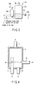
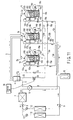
- high-pressure compressors 1a, 1b and 1c are covered by a closed casing 100 each.
- a motor and a compression element 103 are housed in the closed casing 100.
- the motor is formed of a rotor 101 and a stator 102, and the compression element 103 is driven by means of the motor.
- the compression element 103 sucks in a refrigerant (gaseous refrigerant) through a refrigerant inlet port 104 at the lower part of the closed casing 100, and compresses the sucked refrigerant and discharges it into the closed casing 100.
- the closed casing 100 contains a lubricating oil L for the lubrication of various components such as the compression element 103.
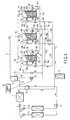
- the refrigerant that is run through the high-pressure-side pipe 3 flows into a refrigerant pipe 5 via an oil separator 4.
- the oil separator 4 separates and holds the lubricating oil L that is contained by the refrigerant.
- the refrigerant that is run from the oil separator 4 into the refrigerant pipe 5 flows through a four-way valve 6 into an outdoor heat exchanger 7.
- the refrigerant (liquid refrigerant) having passed through the outdoor heat exchanger 7 flows into a plurality of indoor heat exchangers 112 via a liquid-side packed valve 8 and a plurality of expansion valves 111.
- the refrigerant that is run through the low-pressure-side pipe passes through refrigerant inlet pipes 12a, 12b and 12c and suction cups 13a, 13b and 13c and is sucked into the compression element 103 through the refrigerant inlet ports 104 of the respective closed casings 100 of the compressors 1a, 1b and 1c.
- the check valves 15a, 15b and 15c prevent the refrigerant and the lubricating oil L from flowing back from the collecting pipe 17 to the compressors 1a, 1b and 1c.
- the capillary tubes 19a, 19b and 19c have resistances (throttles) lower than those of the capillary tubes 16a, 16b and 16c.
- the portions of the lubricating oil L having flowed into the oil pipes 14a, 14b and 14c pass through the capillary tubes 16a, 16b and 16c and join in the collecting pipe 17. Then, the oil is distributed to the oil pipes 18a, 18b and 18c through the collecting pipe 17.
- the lubricating oil L distributed to the oil pipes 18a, 18b and 18c flows into the refrigerant inlet pipes 12a, 12b and 12c through the capillary tubes 19a, 19b and 19c.
- the lubricating oil L that is run through the refrigerant inlet pipes 12a, 12b and 12c, along with the refrigerant circulated in the refrigerating cycle, is sucked into the compressors 1a, 1b and 1c.
- the temperature of the lubricating oil L that flows into the oil pipes 14a, 14b and 14c is high. If a large amount of this high-temperature lubricating oil L is bypassed on the suction side of the compressors 1a, 1b and 1c, the temperature of the refrigerant that is sucked into the compressors 1a, 1b and 1c rises extraordinarily. If the temperature of the refrigerant sucked into the compressors 1a, 1b and 1c rises extraordinarily, the running efficiency of the refrigerating cycle lowers, and the windings of the respective motors of the compressors 1a, 1b and 1c overheat inevitably.
- the lubricating oil L that flows out from the respective closed casings 100 of the individual compressors are collected in the single collecting pipe 17, and the lubricating oil L collected in the collecting pipe 17 is distributed to the compressors.
- the lubricating oil L can be supplied equally to the compressors without regard to the number of compressors.
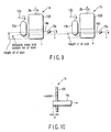
- an allowable lower limit position for the oil level is predetermined in the closed casing 100 of the compressor 1a.
- the allowable lower limit position for the oil level is equivalent to a necessary minimum quantity of lubricating oil for the operation of the compressor 1a.
- the oil pipe 14a is connected at a position higher than the allowable lower limit position for the oil level.
- the oil levels of the lubricating oil L in the respective closed casings 100 of the compressors 1a, 1b and 1c can be easily kept higher than the allowable lower limit position for the oil level.
- the present embodiment shares other configurations, functions, and effects with the first and third embodiments.
- An oil return pipe 23 is connected to the underside portion of the oil separator 4, and the other end of the oil return pipe 23 is connected to the collecting pipe 17.
- the oil return pipe 23 is provided with an on/off valve 24. If the on/off valve 24 opens, the lubricating oil L in the oil separator 4 is guided through the oil return pipe 23 into the collecting pipe 17.
- the on/off valve 24 is controlled by means of a control unit 30.
- the control unit 30 opens the on/off valve 24 in a situation such that the oil levels of the lubricating oil L in the respective closed casings 100 of the compressors 1a, 1b and 1c easily lower, e.g., at the start of operation of the compressors or at the time of defrosting operation.
- the on/off valve 24 opens,to allow the lubricating oil L in the oil separator 4 to be guided through the oil return pipe 23 into the collecting pipe 17.
- the refrigerant pipe 5 has at least one opening 5h through which the lubricating oil L in the oil separator 4 is fetched.
- the position of the opening 5h corresponds to a location between the top position (position indicated by two-dot chain line in the drawing) of the inside diameter of the oil return pipe 21 that is connected to the sidewall of the oil separator 4 and the center position (position indicated by dashed line in the drawing) of the inside diameter of the oil return pipe 21.
- the quantity of the lubricating oil L that flows into the oil return pipe 21 is larger than the quantity of the lubricating oil L that 4flows into the opening 5h.
- the quantity of return flows of the lubricating oil L from the oil separator 4 to the compressors 1a, 1b and 1c is made larger than the outflow of the lubricating oil L from the oil separator 4 into the refrigerating cycle.
- the resistance of the capillary tube 22 of the oil return pipe 21 is higher than the resistances of capillary tubes 16a, 16b and 16c of the oil pipes 14a, 14b and 14c.
- the present embodiment shares other configurations, functions, and effects with the first and third embodiments.
- the lubricating oil L having flowed from the closed casing 100 of the running compressor 1a into the oil pipe 14a passes through the collecting pipe 17, oil pipe 18a, and inlet pipe 12a and is recovered by the compressor 1a. As this is done, the lubricating oil L that is run through the collecting pipe 17 is urged to flow into the respective closed casings 100 of the compressors 1b and 1c through the oil pipes 18b and 18c and the oil pipes 14b and 14c. Since the oil pipes 14b and 14c are provided with the check valves 15b and 15c, respectively, however, there is no possibility of the lubricating oil L in the collecting pipe 17 uselessly flowing through the respective closed casings 100 of the compressors 1b and 1c.
- the respective refrigerant discharge pipes 2b and 2c of the compressors 1b and 1c which are second and third, respectively, in the priority order of operation, are provided with the check valves 41b and 41c, respectively.
- the refrigerant discharge pipe 2a of the compressor 1a with the first priority order of operation is not provided with any check valve.
- the lubricating oil L Since the leakage of the lubricating oil L is prevented in this manner, the lubricating oil can be prevented from running out when the compressor 1c is started next. In consequence, the compression element 3 of the compressor 1c can avoid being damaged.
- the suction pressures that are transmitted from the refrigerant inlet pipes 12a and 12b to the collecting pipe 17 effectively act on the closed casing 100 of the compressor 1c through the oil pipe 14c.
- the surplus portion of the lubricating oil L in the closed casing 100 of the compressor 1c can efficiently flows through the oil pipe 14c into the collecting pipe 17.
- the lubricating oil L run through the collecting pipe 17 can be efficiently supplied to the running compressors 1a and 1b through the oil pipes 18a and 18b and the refrigerant inlet pipes 12a and 12b. Further, the lubricating oil L can be prevented from uselessly staying in the closed casing 100 of the compressor 1c.
- the present embodiment shares other configurations, functions, and effects with the first and third embodiments.
- the present embodiment shares other configurations, functions, and effects with the ninth embodiment.
- connection position of the oil pipe 14a is set so that the quantity of the lubricating oil L held between the allowable lower limit position for the oil level of the closed casing 100 and the oil inlet of the oil pipe 14a is larger than the quantity of the lubricating oil L held between allowable lower limit positions for the oil levels of the respective closed casings 100 of the other compressors 1b and 1c and the respective oil inlets of the oil pipes 14b and 14c.
- connection configuration of the oil pipes 14a, 14b and 14c to the respective casings of the compressors of the foregoing embodiments is defined.
- the quantity of return flows of the lubricating oil L from the compressors 1a, 1b and 1c to the oil pipes 14a, 14b and 14c can be kept appropriate.
- the lubricating oil L can be homogenized with higher reliability.
- the present embodiment shares other configurations, functions, and effects with the fifth embodiment.
Abstract
Description
Claims (15)
- A refrigerating apparatus comprising:a plurality of compressors which suck in and discharge a refrigerant, the compressors being covered by a closed casing which contains the discharged refrigerant and a lubricating oil each;a plurality of refrigerant discharge pipes through which the refrigerant discharged from the compressors passes, the refrigerant discharge pipes being connected to one another;a plurality of refrigerant inlet pipes through which the refrigerant sucked into the compressors passes, the refrigerant inlet pipes being connected to one another;a plurality of first oil pipes into which surplus portions of the lubricating oil in the respective closed casings of the compressors flow;one collecting pipe in which the lubricating oil portions in the first oil pipes join together;a plurality of second oil pipes to which the lubricating oil in the collecting pipe is distributed, the second oil pipes being connected to the refrigerant inlet pipes, individually;a plurality of first pressure reducing units located in the first oil pipes, individually; anda plurality of second pressure reducing units located in the second oil pipes, individually.
- A refrigerating apparatus according to claim 1, which further comprises a plurality of check valves for backflow prevention located in the first oil pipes, individually.
- A refrigerating apparatus according to claim 1, wherein the first oil pipes are connected individually to the respective closed casings of the compressors, the positions of the connections being higher than a predetermined allowable lower limit position for the oil level.
- A refrigerating apparatus according to claim 1, wherein the resistances of the second pressure reducing units are higher than the resistances of the first pressure reducing units.
- A refrigerating apparatus according to claim 1, which further comprises: one oil separator which separates a lubricating oil contained by the refrigerant discharged from the compressors; one oil return pipe which guides the oil separated by means of the oil separator into the collecting pipe, the oil return pipe being connected to the oil separator; and one third pressure reducing unit located in the oil return pipe.
- A refrigerating apparatus according to claim 5, wherein the resistances of the second pressure reducing units are higher than the resistances of the first pressure reducing units and resistance of the third pressure reducing unit.
- A refrigerating apparatus according to claim 1, which further comprises: one oil separator which separates a lubricating oil contained by the refrigerant discharged from the compressors; one first oil return pipe which is connected to the side face of the oil separator and guides that portion of the lubricating oil in the oil separator which is located above the position of connection into the collecting pipe; one third pressure reducing unit located in the first oil return pipe; one second oil return pipe which guides the lubricating oil in the oil'separator into the collecting pipe, the second oil return pipe being connected to the lower part of the oil separator; and one on/off valve located in the second oil return pipe.
- A refrigerating apparatus according to claim 7, which further comprises a refrigerant pipe through which the refrigerant in the oil separator flows out, the refrigerant pipe being inserted in the oil separator and having at least one opening through which the lubricating oil in the oil separator is fetched, the position of the opening corresponding to a location between the top position and the center position of the inside diameter of the first oil return pipe connected to the side face of the oil separator.
- A refrigerating apparatus according to claim 5, wherein the third pressure reducing unit has a resistance higher than those of the first pressure reducing units.
- A refrigerating apparatus according to claim 1, wherein the compressors are different in priority order of operation.
- A refrigerating apparatus according to claim 10, which further comprises one or a plurality of check valves located in one or a plurality of refrigerant discharge pipes corresponding to one or a plurality of compressors not higher in the priority order, among the refrigerant discharge pipes.
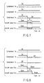
- A refrigerating apparatus according to claim 10, which further comprises: a plurality of on/off valves located individually in a plurality of refrigerant discharge pipes corresponding to a plurality of compressors higher in the priority order, among the refrigerant discharge pipes; and a control unit which closes the on/off valves corresponding to a plurality of running compressors for a given time when a plurality of compressors higher in the priority order are running with the remaining compressors stopped.
- A refrigerating apparatus according to claim 10, which further comprises: a plurality of on/off valves located individually in a plurality of refrigerant discharge pipes corresponding to a plurality of compressors higher in the priority order, among the refrigerant discharge pipes; and a control unit which opens the on/off valves when said plurality of compressors higher in the priority order are running and immediately closes the on/off valves corresponding to the running compressors and closes the on/off valve corresponding to the stopped compressor after the passage of a given time if at least one of the running compressors is stopped.
- A refrigerating apparatus according to claim 10, wherein the quantity of the lubricating oil held between an allowable lower limit position for the oil level of the closed casing of the compressor with the first priority order and the oil inlet of first oil pipe, into which the lubricating oil in the closed casing flows, is larger than the quantity of the lubricating oil held between allowable lower limit positions for the oil levels of the respective closed casings of the other compressors and the oil inlets of the first oil pipes, into which the lubricating oil in the closed casings flows.
- A refrigerating apparatus according to claim 1, wherein each said first oil pipe penetrates the sidewall of the closed casing of each said compressor so as to project for a given length in the closed casing.
Applications Claiming Priority (3)
| Application Number | Priority Date | Filing Date | Title |
|---|---|---|---|
| JP2001322760 | 2001-10-19 | ||
| JP2001322760A JP4108957B2 (en) | 2001-10-19 | 2001-10-19 | Refrigeration equipment |
| PCT/JP2002/010535 WO2003036188A1 (en) | 2001-10-19 | 2002-10-10 | Refrigerating equipment |
Publications (3)
| Publication Number | Publication Date |
|---|---|
| EP1443286A1 true EP1443286A1 (en) | 2004-08-04 |
| EP1443286A4 EP1443286A4 (en) | 2009-09-30 |
| EP1443286B1 EP1443286B1 (en) | 2012-11-21 |
Family
ID=19139752
Family Applications (1)
| Application Number | Title | Priority Date | Filing Date |
|---|---|---|---|
| EP02775318A Expired - Fee Related EP1443286B1 (en) | 2001-10-19 | 2002-10-10 | Refrigerating equipment |
Country Status (5)
| Country | Link |
|---|---|
| EP (1) | EP1443286B1 (en) |
| JP (1) | JP4108957B2 (en) |
| KR (1) | KR100555424B1 (en) |
| CN (1) | CN100406815C (en) |
| WO (1) | WO2003036188A1 (en) |
Cited By (14)
| Publication number | Priority date | Publication date | Assignee | Title |
|---|---|---|---|---|
| EP1677057A2 (en) * | 2004-12-28 | 2006-07-05 | Samsung Electronics Co., Ltd. | Heat pump with compressor oil distribution |
| WO2008108518A2 (en) | 2007-03-02 | 2008-09-12 | Lg Electronics Inc. | Air conditioner and control method thereof |
| EP2101126A2 (en) * | 2008-03-10 | 2009-09-16 | Officine Mario Dorin S.p.A | Compression system for a refrigerant of a refrigeration plant or the like |
| FR2966569A1 (en) * | 2010-10-26 | 2012-04-27 | Danfoss Commercial Compressors | REFRIGERATION SYSTEM |
| FR2968731A1 (en) * | 2010-12-13 | 2012-06-15 | Danfoss Commercial Compressors | THERMODYNAMIC SYSTEM EQUIPPED WITH A PLURALITY OF COMPRESSORS |
| WO2012122114A3 (en) * | 2011-03-04 | 2013-04-04 | Brooks Automation, Inc. | Helium management control system |
| EP2375192A3 (en) * | 2010-02-25 | 2014-01-29 | Mitsubishi Heavy Industries, Ltd. | Air-conditioning apparatus |
| CN103573626A (en) * | 2012-08-02 | 2014-02-12 | 珠海格力电器股份有限公司 | Compressor parallel system and double-rotor compressor of same |
| EP2730862A1 (en) * | 2012-11-12 | 2014-05-14 | LG Electronics Inc. | Air conditioner with an oil separator |
| EP3273061A1 (en) * | 2016-03-30 | 2018-01-24 | Mitsubishi Heavy Industries Thermal Systems, Ltd. | Hermetic two-stage compressor and compressor system |
| EP2538155A4 (en) * | 2010-02-15 | 2018-04-04 | Toshiba Carrier Corporation | Air conditioner |
| US11199347B2 (en) | 2017-05-10 | 2021-12-14 | Mitsubishi Electric Corporation | Oil separation device and refrigeration cycle apparatus |
| FR3134152A1 (en) * | 2022-03-31 | 2023-10-06 | Danfoss Commercial Compressors | A multiple compressor system having normally open valves in oil balancing connections |
| US11796227B2 (en) | 2018-05-24 | 2023-10-24 | Hill Phoenix, Inc. | Refrigeration system with oil control system |
Families Citing this family (13)
| Publication number | Priority date | Publication date | Assignee | Title |
|---|---|---|---|---|
| JP3478292B2 (en) * | 2002-05-28 | 2003-12-15 | ダイキン工業株式会社 | Compression mechanism of refrigeration system |
| KR100675797B1 (en) * | 2004-12-30 | 2007-02-02 | 삼성전자주식회사 | Air conditioner |
| JP4464333B2 (en) | 2005-08-12 | 2010-05-19 | 三星電子株式会社 | Compressor oil leveling device and refrigerator |
| JP4948240B2 (en) * | 2007-04-09 | 2012-06-06 | 三菱電機株式会社 | Refrigeration cycle equipment |
| JP5478927B2 (en) * | 2009-03-31 | 2014-04-23 | 三菱重工業株式会社 | Refrigeration equipment |
| WO2014154046A1 (en) * | 2013-03-29 | 2014-10-02 | 艾默生环境优化技术(苏州)有限公司 | Compressor system and control method therefor |
| CN104074726B (en) * | 2013-03-29 | 2016-08-17 | 艾默生环境优化技术(苏州)有限公司 | Compressor system and control method thereof |
| KR101337234B1 (en) * | 2013-08-05 | 2013-12-05 | 전제호 | Multi control method for a plurality of air compressors |
| CN104654667B (en) * | 2013-11-25 | 2017-11-21 | 珠海格力电器股份有限公司 | The outdoor unit modules of multiple on-line system and there is its multiple on-line system |
| CN104457031A (en) * | 2014-09-30 | 2015-03-25 | 广东志高暖通设备股份有限公司 | Multi-split air conditioning system and oil balancing devices and control method of multi-split air conditioning system |
| CN104315756A (en) * | 2014-09-30 | 2015-01-28 | 广东志高暖通设备股份有限公司 | VRV (variable refrigerant volume) air conditioning system and oil balance device and control method thereof |
| CN104236171A (en) * | 2014-09-30 | 2014-12-24 | 广东志高暖通设备股份有限公司 | VRF air conditioning system, oil balancing device of VRF air conditioning system and control method of VRF air conditioning system |
| CN107747544B (en) | 2017-11-07 | 2019-07-09 | 苏州英华特涡旋技术有限公司 | A kind of compressor with oil equalizing pipe, parallel compressor group and oily method |
Citations (3)
| Publication number | Priority date | Publication date | Assignee | Title |
|---|---|---|---|---|
| US5327997A (en) * | 1993-01-22 | 1994-07-12 | Temprite, Inc. | Lubrication management system |
| WO1995035462A1 (en) * | 1994-06-17 | 1995-12-28 | Refrigerant Monitoring Systems Pty. Ltd. | Oil level control apparatus |
| JPH085169A (en) * | 1994-06-21 | 1996-01-12 | Matsushita Refrig Co Ltd | Air conditioner |
Family Cites Families (2)
| Publication number | Priority date | Publication date | Assignee | Title |
|---|---|---|---|---|
| JP3403868B2 (en) * | 1995-07-05 | 2003-05-06 | 東芝キヤリア株式会社 | Air conditioner |
| JP3434993B2 (en) * | 1996-11-12 | 2003-08-11 | 株式会社日立製作所 | Air conditioner |
-
2001
- 2001-10-19 JP JP2001322760A patent/JP4108957B2/en not_active Expired - Fee Related
-
2002
- 2002-10-10 CN CN028207572A patent/CN100406815C/en not_active Expired - Fee Related
- 2002-10-10 KR KR1020047004701A patent/KR100555424B1/en not_active IP Right Cessation
- 2002-10-10 EP EP02775318A patent/EP1443286B1/en not_active Expired - Fee Related
- 2002-10-10 WO PCT/JP2002/010535 patent/WO2003036188A1/en active Application Filing
Patent Citations (3)
| Publication number | Priority date | Publication date | Assignee | Title |
|---|---|---|---|---|
| US5327997A (en) * | 1993-01-22 | 1994-07-12 | Temprite, Inc. | Lubrication management system |
| WO1995035462A1 (en) * | 1994-06-17 | 1995-12-28 | Refrigerant Monitoring Systems Pty. Ltd. | Oil level control apparatus |
| JPH085169A (en) * | 1994-06-21 | 1996-01-12 | Matsushita Refrig Co Ltd | Air conditioner |
Non-Patent Citations (1)
| Title |
|---|
| See also references of WO03036188A1 * |
Cited By (25)
| Publication number | Priority date | Publication date | Assignee | Title |
|---|---|---|---|---|
| EP1677057A2 (en) * | 2004-12-28 | 2006-07-05 | Samsung Electronics Co., Ltd. | Heat pump with compressor oil distribution |
| EP1677057A3 (en) * | 2004-12-28 | 2009-06-03 | Samsung Electronics Co., Ltd. | Heat pump with compressor oil distribution |
| WO2008108518A2 (en) | 2007-03-02 | 2008-09-12 | Lg Electronics Inc. | Air conditioner and control method thereof |
| EP2132498A2 (en) * | 2007-03-02 | 2009-12-16 | LG Electronics Inc. | Air conditioner and control method thereof |
| EP2132498A4 (en) * | 2007-03-02 | 2012-01-25 | Lg Electronics Inc | Air conditioner and control method thereof |
| EP2101126A2 (en) * | 2008-03-10 | 2009-09-16 | Officine Mario Dorin S.p.A | Compression system for a refrigerant of a refrigeration plant or the like |
| EP2101126A3 (en) * | 2008-03-10 | 2011-10-12 | Officine Mario Dorin S.p.A | Compression system for a refrigerant of a refrigeration plant or the like |
| EP2538155A4 (en) * | 2010-02-15 | 2018-04-04 | Toshiba Carrier Corporation | Air conditioner |
| EP2375192A3 (en) * | 2010-02-25 | 2014-01-29 | Mitsubishi Heavy Industries, Ltd. | Air-conditioning apparatus |
| FR2966569A1 (en) * | 2010-10-26 | 2012-04-27 | Danfoss Commercial Compressors | REFRIGERATION SYSTEM |
| WO2012056150A3 (en) * | 2010-10-26 | 2012-08-30 | Danfoss Commercial Compressors | Refrigeration system |
| WO2012080611A1 (en) * | 2010-12-13 | 2012-06-21 | Danfoss Commercial Compressors | Thermodynamic system provided with a plurality of compressors |
| FR2968731A1 (en) * | 2010-12-13 | 2012-06-15 | Danfoss Commercial Compressors | THERMODYNAMIC SYSTEM EQUIPPED WITH A PLURALITY OF COMPRESSORS |
| US10900699B2 (en) | 2011-03-04 | 2021-01-26 | Edwards Vacuum Llc | Helium management control system |
| CN104094066A (en) * | 2011-03-04 | 2014-10-08 | 布鲁克机械公司 | Helium management control system |
| US10113781B2 (en) | 2011-03-04 | 2018-10-30 | Brooks Automation, Inc. | Helium management control system |
| WO2012122114A3 (en) * | 2011-03-04 | 2013-04-04 | Brooks Automation, Inc. | Helium management control system |
| CN103573626A (en) * | 2012-08-02 | 2014-02-12 | 珠海格力电器股份有限公司 | Compressor parallel system and double-rotor compressor of same |
| EP2730862A1 (en) * | 2012-11-12 | 2014-05-14 | LG Electronics Inc. | Air conditioner with an oil separator |
| US9500396B2 (en) | 2012-11-12 | 2016-11-22 | Lg Electronics Inc. | Oil separator and air conditioner using the same |
| EP3273061A1 (en) * | 2016-03-30 | 2018-01-24 | Mitsubishi Heavy Industries Thermal Systems, Ltd. | Hermetic two-stage compressor and compressor system |
| US11199347B2 (en) | 2017-05-10 | 2021-12-14 | Mitsubishi Electric Corporation | Oil separation device and refrigeration cycle apparatus |
| US11796227B2 (en) | 2018-05-24 | 2023-10-24 | Hill Phoenix, Inc. | Refrigeration system with oil control system |
| EP3572741B1 (en) * | 2018-05-24 | 2024-03-27 | Hill Phoenix Inc. | Refrigeration system with oil control system |
| FR3134152A1 (en) * | 2022-03-31 | 2023-10-06 | Danfoss Commercial Compressors | A multiple compressor system having normally open valves in oil balancing connections |
Also Published As
| Publication number | Publication date |
|---|---|
| KR100555424B1 (en) | 2006-02-24 |
| CN100406815C (en) | 2008-07-30 |
| EP1443286B1 (en) | 2012-11-21 |
| EP1443286A4 (en) | 2009-09-30 |
| CN1571908A (en) | 2005-01-26 |
| JP4108957B2 (en) | 2008-06-25 |
| JP2003130474A (en) | 2003-05-08 |
| KR20040039461A (en) | 2004-05-10 |
| WO2003036188A1 (en) | 2003-05-01 |
Similar Documents
| Publication | Publication Date | Title |
|---|---|---|
| EP1443286B1 (en) | Refrigerating equipment | |
| CN1950613B (en) | System and method for variable speed operation of a screw compressor | |
| JP4013261B2 (en) | Refrigeration equipment | |
| US7721559B2 (en) | Multi-type air conditioner and method for controlling the same | |
| EP2015003B1 (en) | Refrigerating apparatus | |
| US20140238066A1 (en) | System Including High-Side and Low-Side Compressors | |
| EP2525170B1 (en) | Controlling method for an air conditioner. | |
| JP2009150628A (en) | Oil equalizing system for high pressure shell compressor used in air conditioner | |
| JP2007285675A (en) | Refrigerating appliance | |
| WO2014083901A1 (en) | Compressor, refrigeration cycle device, and heat pump hot-water supply device | |
| CN110582677B (en) | Air conditioner | |
| JP2014196874A (en) | Refrigeration cycle device and air conditioner including the same | |
| EP3431903A1 (en) | Air-conditioning apparatus and method for operating the same | |
| JP4031560B2 (en) | Air conditioner | |
| JP2009092060A (en) | Oil separator | |
| JP4591402B2 (en) | Refrigeration equipment | |
| JP3848098B2 (en) | Air conditioner | |
| KR100710368B1 (en) | Multi-type air conditioner | |
| KR101203848B1 (en) | A compressor oil retrieving apparatus of multi-type air conditioner | |
| JP2004205175A (en) | Refrigerator | |
| CN111512098B (en) | Refrigeration cycle device | |
| JP4720593B2 (en) | Refrigeration equipment | |
| JP2013139896A (en) | Refrigeration apparatus | |
| JP2508811B2 (en) | Air conditioner | |
| JP2015148194A (en) | Refrigerating circuit |
Legal Events
| Date | Code | Title | Description |
|---|---|---|---|
| PUAI | Public reference made under article 153(3) epc to a published international application that has entered the european phase |
Free format text: ORIGINAL CODE: 0009012 |
|
| 17P | Request for examination filed |
Effective date: 20040422 |
|
| AK | Designated contracting states |
Kind code of ref document: A1 Designated state(s): AT BE BG CH CY CZ DE DK EE ES FI FR GB GR IE IT LI LU MC NL PT SE SK TR |
|
| AX | Request for extension of the european patent |
Extension state: AL LT LV MK RO SI |
|
| A4 | Supplementary search report drawn up and despatched |
Effective date: 20090828 |
|
| RIC1 | Information provided on ipc code assigned before grant |
Ipc: F25B 1/00 20060101AFI20030508BHEP Ipc: F04C 23/00 20060101ALI20090824BHEP Ipc: F04C 29/02 20060101ALI20090824BHEP |
|
| REG | Reference to a national code |
Ref country code: DE Ref legal event code: 8566 |
|
| 17Q | First examination report despatched |
Effective date: 20091117 |
|
| GRAP | Despatch of communication of intention to grant a patent |
Free format text: ORIGINAL CODE: EPIDOSNIGR1 |
|
| GRAS | Grant fee paid |
Free format text: ORIGINAL CODE: EPIDOSNIGR3 |
|
| GRAA | (expected) grant |
Free format text: ORIGINAL CODE: 0009210 |
|
| AK | Designated contracting states |
Kind code of ref document: B1 Designated state(s): FR GB IT |
|
| REG | Reference to a national code |
Ref country code: GB Ref legal event code: FG4D |
|
| PLBE | No opposition filed within time limit |
Free format text: ORIGINAL CODE: 0009261 |
|
| STAA | Information on the status of an ep patent application or granted ep patent |
Free format text: STATUS: NO OPPOSITION FILED WITHIN TIME LIMIT |
|
| 26N | No opposition filed |
Effective date: 20130822 |
|
| REG | Reference to a national code |
Ref country code: FR Ref legal event code: PLFP Year of fee payment: 15 |
|
| REG | Reference to a national code |
Ref country code: FR Ref legal event code: PLFP Year of fee payment: 16 |
|
| PGFP | Annual fee paid to national office [announced via postgrant information from national office to epo] |
Ref country code: FR Payment date: 20170918 Year of fee payment: 16 |
|
| PGFP | Annual fee paid to national office [announced via postgrant information from national office to epo] |
Ref country code: GB Payment date: 20171004 Year of fee payment: 16 Ref country code: IT Payment date: 20171024 Year of fee payment: 16 |
|
| GBPC | Gb: european patent ceased through non-payment of renewal fee |
Effective date: 20181010 |
|
| PG25 | Lapsed in a contracting state [announced via postgrant information from national office to epo] |
Ref country code: FR Free format text: LAPSE BECAUSE OF NON-PAYMENT OF DUE FEES Effective date: 20181031 |
|
| PG25 | Lapsed in a contracting state [announced via postgrant information from national office to epo] |
Ref country code: IT Free format text: LAPSE BECAUSE OF NON-PAYMENT OF DUE FEES Effective date: 20181010 Ref country code: GB Free format text: LAPSE BECAUSE OF NON-PAYMENT OF DUE FEES Effective date: 20181010 |