EP3572741B1 - Refrigeration system with oil control system - Google Patents
Refrigeration system with oil control system Download PDFInfo
- Publication number
- EP3572741B1 EP3572741B1 EP19176127.9A EP19176127A EP3572741B1 EP 3572741 B1 EP3572741 B1 EP 3572741B1 EP 19176127 A EP19176127 A EP 19176127A EP 3572741 B1 EP3572741 B1 EP 3572741B1
- Authority
- EP
- European Patent Office
- Prior art keywords
- oil
- suction line
- compressors
- refrigerant
- control valve
- Prior art date
- Legal status (The legal status is an assumption and is not a legal conclusion. Google has not performed a legal analysis and makes no representation as to the accuracy of the status listed.)
- Active
Links
- 238000005057 refrigeration Methods 0.000 title claims description 72
- CURLTUGMZLYLDI-UHFFFAOYSA-N Carbon dioxide Chemical compound O=C=O CURLTUGMZLYLDI-UHFFFAOYSA-N 0.000 claims description 168
- 239000001569 carbon dioxide Substances 0.000 claims description 159
- 229910002092 carbon dioxide Inorganic materials 0.000 claims description 159
- 239000003507 refrigerant Substances 0.000 claims description 105
- 238000000034 method Methods 0.000 claims description 48
- 238000005259 measurement Methods 0.000 claims description 18
- 230000004044 response Effects 0.000 claims description 13
- 238000001816 cooling Methods 0.000 claims description 11
- 230000008569 process Effects 0.000 description 28
- 239000012530 fluid Substances 0.000 description 24
- 239000007788 liquid Substances 0.000 description 12
- 239000000203 mixture Substances 0.000 description 11
- 238000004891 communication Methods 0.000 description 10
- 238000012545 processing Methods 0.000 description 8
- 230000006835 compression Effects 0.000 description 6
- 238000007906 compression Methods 0.000 description 6
- 238000010586 diagram Methods 0.000 description 4
- 238000012986 modification Methods 0.000 description 3
- 230000004048 modification Effects 0.000 description 3
- 230000000737 periodic effect Effects 0.000 description 3
- RYGMFSIKBFXOCR-UHFFFAOYSA-N Copper Chemical compound [Cu] RYGMFSIKBFXOCR-UHFFFAOYSA-N 0.000 description 2
- 230000003044 adaptive effect Effects 0.000 description 2
- 230000005494 condensation Effects 0.000 description 2
- 238000009833 condensation Methods 0.000 description 2
- 229910052802 copper Inorganic materials 0.000 description 2
- 239000010949 copper Substances 0.000 description 2
- 238000001704 evaporation Methods 0.000 description 2
- 230000008020 evaporation Effects 0.000 description 2
- 230000006870 function Effects 0.000 description 2
- 230000003287 optical effect Effects 0.000 description 2
- 238000012552 review Methods 0.000 description 2
- 238000012546 transfer Methods 0.000 description 2
- 230000004075 alteration Effects 0.000 description 1
- 238000003491 array Methods 0.000 description 1
- 230000001413 cellular effect Effects 0.000 description 1
- 239000003086 colorant Substances 0.000 description 1
- 238000010276 construction Methods 0.000 description 1
- 230000001276 controlling effect Effects 0.000 description 1
- 238000013461 design Methods 0.000 description 1
- 230000000694 effects Effects 0.000 description 1
- 239000000463 material Substances 0.000 description 1
- 239000003595 mist Substances 0.000 description 1
- 238000003909 pattern recognition Methods 0.000 description 1
- 230000001105 regulatory effect Effects 0.000 description 1
- 229920006395 saturated elastomer Polymers 0.000 description 1
- 239000007787 solid Substances 0.000 description 1
- 238000006467 substitution reaction Methods 0.000 description 1
Images

Classifications
-
- F—MECHANICAL ENGINEERING; LIGHTING; HEATING; WEAPONS; BLASTING
- F25—REFRIGERATION OR COOLING; COMBINED HEATING AND REFRIGERATION SYSTEMS; HEAT PUMP SYSTEMS; MANUFACTURE OR STORAGE OF ICE; LIQUEFACTION SOLIDIFICATION OF GASES
- F25B—REFRIGERATION MACHINES, PLANTS OR SYSTEMS; COMBINED HEATING AND REFRIGERATION SYSTEMS; HEAT PUMP SYSTEMS
- F25B9/00—Compression machines, plants or systems, in which the refrigerant is air or other gas of low boiling point
- F25B9/002—Compression machines, plants or systems, in which the refrigerant is air or other gas of low boiling point characterised by the refrigerant
- F25B9/008—Compression machines, plants or systems, in which the refrigerant is air or other gas of low boiling point characterised by the refrigerant the refrigerant being carbon dioxide
-
- F—MECHANICAL ENGINEERING; LIGHTING; HEATING; WEAPONS; BLASTING
- F25—REFRIGERATION OR COOLING; COMBINED HEATING AND REFRIGERATION SYSTEMS; HEAT PUMP SYSTEMS; MANUFACTURE OR STORAGE OF ICE; LIQUEFACTION SOLIDIFICATION OF GASES
- F25B—REFRIGERATION MACHINES, PLANTS OR SYSTEMS; COMBINED HEATING AND REFRIGERATION SYSTEMS; HEAT PUMP SYSTEMS
- F25B31/00—Compressor arrangements
- F25B31/002—Lubrication
- F25B31/004—Lubrication oil recirculating arrangements
-
- C—CHEMISTRY; METALLURGY
- C09—DYES; PAINTS; POLISHES; NATURAL RESINS; ADHESIVES; COMPOSITIONS NOT OTHERWISE PROVIDED FOR; APPLICATIONS OF MATERIALS NOT OTHERWISE PROVIDED FOR
- C09K—MATERIALS FOR MISCELLANEOUS APPLICATIONS, NOT PROVIDED FOR ELSEWHERE
- C09K5/00—Heat-transfer, heat-exchange or heat-storage materials, e.g. refrigerants; Materials for the production of heat or cold by chemical reactions other than by combustion
- C09K5/02—Materials undergoing a change of physical state when used
- C09K5/04—Materials undergoing a change of physical state when used the change of state being from liquid to vapour or vice versa
- C09K5/041—Materials undergoing a change of physical state when used the change of state being from liquid to vapour or vice versa for compression-type refrigeration systems
-
- F—MECHANICAL ENGINEERING; LIGHTING; HEATING; WEAPONS; BLASTING
- F25—REFRIGERATION OR COOLING; COMBINED HEATING AND REFRIGERATION SYSTEMS; HEAT PUMP SYSTEMS; MANUFACTURE OR STORAGE OF ICE; LIQUEFACTION SOLIDIFICATION OF GASES
- F25B—REFRIGERATION MACHINES, PLANTS OR SYSTEMS; COMBINED HEATING AND REFRIGERATION SYSTEMS; HEAT PUMP SYSTEMS
- F25B1/00—Compression machines, plants or systems with non-reversible cycle
- F25B1/10—Compression machines, plants or systems with non-reversible cycle with multi-stage compression
-
- F—MECHANICAL ENGINEERING; LIGHTING; HEATING; WEAPONS; BLASTING
- F25—REFRIGERATION OR COOLING; COMBINED HEATING AND REFRIGERATION SYSTEMS; HEAT PUMP SYSTEMS; MANUFACTURE OR STORAGE OF ICE; LIQUEFACTION SOLIDIFICATION OF GASES
- F25B—REFRIGERATION MACHINES, PLANTS OR SYSTEMS; COMBINED HEATING AND REFRIGERATION SYSTEMS; HEAT PUMP SYSTEMS
- F25B43/00—Arrangements for separating or purifying gases or liquids; Arrangements for vaporising the residuum of liquid refrigerant, e.g. by heat
- F25B43/02—Arrangements for separating or purifying gases or liquids; Arrangements for vaporising the residuum of liquid refrigerant, e.g. by heat for separating lubricants from the refrigerant
-
- F—MECHANICAL ENGINEERING; LIGHTING; HEATING; WEAPONS; BLASTING
- F25—REFRIGERATION OR COOLING; COMBINED HEATING AND REFRIGERATION SYSTEMS; HEAT PUMP SYSTEMS; MANUFACTURE OR STORAGE OF ICE; LIQUEFACTION SOLIDIFICATION OF GASES
- F25B—REFRIGERATION MACHINES, PLANTS OR SYSTEMS; COMBINED HEATING AND REFRIGERATION SYSTEMS; HEAT PUMP SYSTEMS
- F25B49/00—Arrangement or mounting of control or safety devices
- F25B49/02—Arrangement or mounting of control or safety devices for compression type machines, plants or systems
-
- C—CHEMISTRY; METALLURGY
- C09—DYES; PAINTS; POLISHES; NATURAL RESINS; ADHESIVES; COMPOSITIONS NOT OTHERWISE PROVIDED FOR; APPLICATIONS OF MATERIALS NOT OTHERWISE PROVIDED FOR
- C09K—MATERIALS FOR MISCELLANEOUS APPLICATIONS, NOT PROVIDED FOR ELSEWHERE
- C09K2205/00—Aspects relating to compounds used in compression type refrigeration systems
- C09K2205/10—Components
- C09K2205/106—Carbon dioxide
-
- F—MECHANICAL ENGINEERING; LIGHTING; HEATING; WEAPONS; BLASTING
- F25—REFRIGERATION OR COOLING; COMBINED HEATING AND REFRIGERATION SYSTEMS; HEAT PUMP SYSTEMS; MANUFACTURE OR STORAGE OF ICE; LIQUEFACTION SOLIDIFICATION OF GASES
- F25B—REFRIGERATION MACHINES, PLANTS OR SYSTEMS; COMBINED HEATING AND REFRIGERATION SYSTEMS; HEAT PUMP SYSTEMS
- F25B2309/00—Gas cycle refrigeration machines
- F25B2309/06—Compression machines, plants or systems characterised by the refrigerant being carbon dioxide
-
- F—MECHANICAL ENGINEERING; LIGHTING; HEATING; WEAPONS; BLASTING
- F25—REFRIGERATION OR COOLING; COMBINED HEATING AND REFRIGERATION SYSTEMS; HEAT PUMP SYSTEMS; MANUFACTURE OR STORAGE OF ICE; LIQUEFACTION SOLIDIFICATION OF GASES
- F25B—REFRIGERATION MACHINES, PLANTS OR SYSTEMS; COMBINED HEATING AND REFRIGERATION SYSTEMS; HEAT PUMP SYSTEMS
- F25B2400/00—General features or devices for refrigeration machines, plants or systems, combined heating and refrigeration systems or heat-pump systems, i.e. not limited to a particular subgroup of F25B
- F25B2400/07—Details of compressors or related parts
- F25B2400/075—Details of compressors or related parts with parallel compressors
-
- F—MECHANICAL ENGINEERING; LIGHTING; HEATING; WEAPONS; BLASTING
- F25—REFRIGERATION OR COOLING; COMBINED HEATING AND REFRIGERATION SYSTEMS; HEAT PUMP SYSTEMS; MANUFACTURE OR STORAGE OF ICE; LIQUEFACTION SOLIDIFICATION OF GASES
- F25B—REFRIGERATION MACHINES, PLANTS OR SYSTEMS; COMBINED HEATING AND REFRIGERATION SYSTEMS; HEAT PUMP SYSTEMS
- F25B2400/00—General features or devices for refrigeration machines, plants or systems, combined heating and refrigeration systems or heat-pump systems, i.e. not limited to a particular subgroup of F25B
- F25B2400/23—Separators
-
- F—MECHANICAL ENGINEERING; LIGHTING; HEATING; WEAPONS; BLASTING
- F25—REFRIGERATION OR COOLING; COMBINED HEATING AND REFRIGERATION SYSTEMS; HEAT PUMP SYSTEMS; MANUFACTURE OR STORAGE OF ICE; LIQUEFACTION SOLIDIFICATION OF GASES
- F25B—REFRIGERATION MACHINES, PLANTS OR SYSTEMS; COMBINED HEATING AND REFRIGERATION SYSTEMS; HEAT PUMP SYSTEMS
- F25B2600/00—Control issues
- F25B2600/25—Control of valves
- F25B2600/2515—Flow valves
-
- F—MECHANICAL ENGINEERING; LIGHTING; HEATING; WEAPONS; BLASTING
- F25—REFRIGERATION OR COOLING; COMBINED HEATING AND REFRIGERATION SYSTEMS; HEAT PUMP SYSTEMS; MANUFACTURE OR STORAGE OF ICE; LIQUEFACTION SOLIDIFICATION OF GASES
- F25B—REFRIGERATION MACHINES, PLANTS OR SYSTEMS; COMBINED HEATING AND REFRIGERATION SYSTEMS; HEAT PUMP SYSTEMS
- F25B2700/00—Sensing or detecting of parameters; Sensors therefor
- F25B2700/03—Oil level
Definitions
- the present disclosure relates generally to a refrigeration system and more particularly to a refrigeration system that uses carbon dioxide (i.e., CO 2 ) as a refrigerant.
- CO 2 carbon dioxide
- the present disclosure relates more particularly still to a CO 2 refrigeration system with an oil control system.
- Refrigeration systems are often used to provide cooling to temperature controlled display devices (e.g. cases, merchandisers, etc.) in supermarkets and other similar facilities.
- Vapor compression refrigeration systems are a type of refrigeration system which provides such cooling by circulating a fluid refrigerant (e.g., a liquid and/or vapor) through a thermodynamic vapor compression cycle.
- the refrigerant In a vapor compression cycle, the refrigerant is typically compressed to a high temperature high pressure state (e.g., by a compressor of the refrigeration system), cooled/condensed to a lower temperature state (e.g., in a gas cooler or condenser which absorbs heat from the refrigerant), expanded to a lower pressure (e.g., through an expansion valve), and evaporated to provide cooling by absorbing heat into the refrigerant.
- CO 2 refrigeration systems are a type of vapor compression refrigeration system that use CO 2 as a refrigerant.
- Some CO 2 refrigeration systems include an oil management system which provides oil to one or more compressors of the refrigeration system.
- Oil management systems are typically either active or passive. Active oil control systems use an oil separator to remove oil from the refrigerant and then provide the oil directly to each compressor (e.g., via an oil line connecting the oil separator to each compressor). Passive oil control systems do not include an oil separator and allow the oil to remain mixed with the refrigerant throughout the refrigeration cycle.
- EP1367259A1 describes a freezer system wherein if a refrigerating cycle has been formed, flow-rate adjusting valves are controlled in opening. When the temperature of refrigerant discharged rises above a preset value, a minimum opening for the flow-rate adjusting valves is changed to a value greater than a normal value.
- EP1367259A1 shows a refrigeration system that provides cooling for a refrigeration load a refrigerant, the refrigeration system comprising:a plurality of compressors configured to circulate the refrigerant within the refrigeration system; a suction line configured to deliver the refrigerant to the plurality of compressors in parallel; an oil separator configured to separate oil from the refrigerant; and an oil return line configured to deliver the oil from the oil separator to the suction line, wherein the oil mixes with the refrigerant in the suction line before reaching the compressors.
- the refrigeration system of EP1367259A1 further comprises an oil control valve located along the oil return line and configured to control a flow of oil from the oil separator to the suction line.
- CO 2 refrigeration system that provides cooling for a refrigeration load using carbon dioxide (CO 2 ) as a refrigerant, in accordance with claim 1.
- the CO 2 refrigeration system includes a plurality of oil equalization lines and a plurality of oil equalization valves.
- Each of the oil equalization lines may connect one of the compressors to the oil return line.
- Each of the oil equalization valves may be located along one of the oil equalization lines and configured to control a flow of oil through the oil equalization lines.
- the CO 2 refrigeration system includes a controller configured to periodically open and close the plurality of oil equalization valves. Opening the oil equalization valves may cause any excess oil within the compressors to flow into the oil equalization lines and equalizes an amount of oil within each of the compressors.
- the controller is configured to open the oil control valve in response to a determination that the measured amount of oil within the suction line is less than an oil threshold and keep the oil control valve closed in response to a determination that the measured amount of the oil within the suction line is greater than or equal to the oil threshold.
- Another implementation of the present disclosure is a method for operating a CO 2 refrigeration system that provides cooling for a refrigeration load using carbon dioxide (CO 2 ) as a refrigerant, in accordance with claim 5.
- CO 2 carbon dioxide
- the method includes returning excess oil from the plurality of compressors to the oil return line via a plurality of oil equalization lines.
- Each oil equalization line may connect one of the compressors to the oil return line.
- the method may include operating a plurality of oil equalization valves to control a flow of the excess oil through the oil equalization lines.
- Each oil equalization valve may be located along one of the oil equalization lines.
- the method includes periodically opening and closing the plurality of oil equalization valves. Opening the oil equalization valves may cause any excess oil within the compressors to flow into the oil equalization lines and may equalize an amount of oil within each of the compressors.
- operating the oil control valve includes opening the oil control valve in response to a determination that the measured amount of oil within the suction line is less than an oil threshold and keeping the oil control valve closed in response to a determination that the measured amount of the oil within the suction line is greater than or equal to the oil threshold.
- the controller includes one or more processors and one or more non-transitory computer-readable media storing instructions. When executed by the one or more processors, cause the one or more processors to perform operations including operating a plurality of compressors to circulate the CO 2 refrigerant within the CO 2 refrigeration system and obtaining a measurement of an amount of oil within a suction line coupled to an inlet of the compressors.
- the suction line contains a mixture of oil and the CO 2 refrigerant.
- the operations include comparing the amount of oil within the suction line to an oil threshold and operating an oil control valve to control a flow of oil from an oil separator to the compressor suction line.
- the oil from the oil separator mixes with the CO 2 refrigerant in the compressor suction line before reaching the compressors.
- operating the oil control valve includes opening the oil control valve in response to a determination that the amount of oil within the suction line is less than the oil threshold and keeping the oil control valve closed in response to a determination that the amount of the oil within the suction line is greater than or equal to the oil threshold.
- the operations include obtaining a second measurement of the amount of oil within the suction line after opening the oil control valve to release oil from the oil separator into the suction line and deactivating one or more components of the CO 2 refrigeration system in response to the second measurement of the amount of oil within the suction line being less than the oil threshold.
- the operations include opening a plurality of oil equalization valves connecting the plurality of compressors to an oil return line to equalize oil within each of the compressors and closing the plurality of oil equalization valves after a predetermined amount of time has elapsed.
- opening the plurality of oil equalization valves causes any excess oil from the plurality of compressors to return to the oil return line via a plurality of oil equalization lines.
- Each oil equalization line may connect one of the compressors to the oil return line.
- the oil return line receives both the flow of oil from the oil separator and a flow of oil from the oil equalization lines and delivers oil to the suction line.
- the CO 2 refrigeration system may be a vapor compression refrigeration system which uses primarily carbon dioxide (i.e., CO 2 ) as a refrigerant.
- CO 2 carbon dioxide
- the CO 2 refrigeration system is used to provide cooling for temperature controlled display devices in a supermarket or other similar facility.
- the CO 2 refrigeration system includes an oil control system.
- the CO 2 refrigeration system and/or the oil control system include some or all of the features described in U.S. Provisional Patent Application No. 62/460,984 filed February 20, 2017 .
- the oil control system includes an oil separator configured to remove oil from the CO 2 refrigerant.
- the oil control system uses a semi-active or semi-passive oil control technique. Unlike active oil control systems that provide oil directly to individual compressors, the oil control system provides the oil from the oil separate into a refrigerant suction line that feeds into multiple compressors of the CO 2 refrigeration system. The oil mixes with the CO 2 refrigerant in the suction line before reaching the compressors.
- the oil control system includes several oil equalization lines, each of which connects a compressor of the CO 2 refrigeration system to an oil return line.
- the oil equalization lines may connect to the compressors at connection points defining a target level of oil within each compressor.
- the oil control system may include oil equalization valves located along each oil equalization line. The oil equalization valves can be opened simultaneously to equalize the amount of oil within each compressor. When the oil equalization valves are open, any oil within the compressors above the connection points may flow into the oil equalization lines and into the oil return line, whereas any oil below the connection points may remain within the compressors.
- the oil return line then delivers any returned oil into the compressor suction line to mix with the refrigerant.
- the oil control system includes an oil sensor configured to measure an amount or level of oil within the compressor suction line. If the measured amount of oil in the suction line is less than an oil threshold after the oil equalization procedure has been performed (e.g., two minutes later), an oil control valve may be opened to release oil from the oil separator into the oil return line, which delivers the oil to the compressor suction line. However, if the measured amount of oil in the suction line is greater than or equal to the oil threshold, the oil control valve may remain closed. If the amount of oil in the suction line does not reach the oil threshold after opening the oil control valve, an alarm may be generated and the CO 2 refrigeration system may be shutdown.
- CO 2 refrigeration system 100 may be a vapor compression refrigeration system which uses primarily carbon dioxide (CO 2 ) as a refrigerant.
- CO 2 refrigeration system 100 and is shown to include a system of pipes, conduits, or other fluid channels (e.g., fluid conduits 1, 3, 5, 7, 9, 13, 17, and 19) for transporting the CO 2 refrigerant between various components of CO 2 refrigeration system 100.
- the components of CO 2 refrigeration system 100 are shown to include a gas cooler/condenser 2, a high pressure valve 4, a receiver 6, expansion valves 11, evaporators 12, and compressors 14.
- Gas cooler/condenser 2 may be a heat exchanger or other similar device for removing heat from the CO 2 refrigerant. Gas cooler/condenser 2 is shown receiving CO 2 vapor from fluid conduit 1. In some embodiments, the CO 2 vapor in fluid conduit 1 may have a pressure within a range from approximately 45 bar to approximately 100 bar (i.e., about 640 psig to about 1420 psig), depending on ambient temperature and other operating conditions. In some embodiments, gas cooler/condenser 2 may partially or fully condense CO 2 vapor into liquid CO 2 (e.g., if system operation is in a subcritical region). The condensation process may result in fully saturated CO 2 liquid or a liquid-vapor mixture (e.g., having a thermodynamic quality between zero and one).
- gas cooler/condenser 2 may cool the CO 2 vapor (e.g., by removing superheat) without condensing the CO 2 vapor into CO 2 liquid (e.g., if system operation is in a supercritical region).
- the cooling/condensation process is an isobaric process. Gas cooler/condenser 2 is shown outputting the cooled and/or condensed CO 2 refrigerant into fluid conduit 3.
- High pressure valve 4 receives the cooled and/or condensed CO 2 refrigerant from fluid conduit 3 and outputs the CO 2 refrigerant to fluid conduit 5.
- High pressure valve 4 may control the pressure of the CO 2 refrigerant in gas cooler/condenser 2 by controlling an amount of CO 2 refrigerant permitted to pass through high pressure valve 4.
- high pressure valve 4 is a high pressure thermal expansion valve (e.g., if the pressure in fluid conduit 3 is greater than the pressure in fluid conduit 5). In such embodiments, high pressure valve 4 may allow the CO 2 refrigerant to expand to a lower pressure state.
- the expansion process may be an isenthalpic and/or adiabatic expansion process, resulting in a flash evaporation of the high pressure CO 2 refrigerant to a lower pressure, lower temperature state.
- the expansion process may produce a liquid/vapor mixture (e.g., having a thermodynamic quality between zero and one).
- the CO 2 refrigerant expands to a pressure of approximately 38 bar (e.g., about 540 psig), which corresponds to a temperature of approximately 37° F.
- the CO 2 refrigerant then flows from fluid conduit 5 into receiver 6.
- Receiver 6 collects the CO 2 refrigerant from fluid conduit 5.
- receiver 6 may be a flash tank or other fluid reservoir.
- Receiver 6 includes a CO 2 liquid portion 16 and a CO 2 vapor portion 15 and may contain a partially saturated mixture of CO 2 liquid and CO 2 vapor.
- receiver 6 separates the CO 2 liquid from the CO 2 vapor.
- the CO 2 liquid may exit receiver 6 through fluid conduit 9.
- Fluid conduit 9 may be liquid headers leading to expansion valves 11 and evaporators 12.
- the CO 2 vapor may exit receiver 6 through fluid conduit 7.
- Fluid conduit 7 is shown leading the CO 2 vapor to fluid conduit 13.
- Expansion valves 11 may be electronic expansion valves or other similar expansion valves. Expansion valves 11 are shown receiving liquid CO 2 refrigerant from fluid conduit 9 and outputting the CO 2 refrigerant to evaporators 12. Expansion valves 11 may cause the CO 2 refrigerant to undergo a rapid drop in pressure, thereby expanding the CO 2 refrigerant to a lower pressure, lower temperature state. In some embodiments, expansion valves 11 may expand the CO 2 refrigerant to a pressure of approximately 30 bar. The expansion process may be an isenthalpic and/or adiabatic expansion process.
- Evaporators 12 are shown receiving the cooled and expanded CO 2 refrigerant from expansion valves 11.
- evaporators 12 may be associated with display cases/devices (e.g., if CO 2 refrigeration system 100 is implemented in a supermarket setting).
- Evaporators 12 may be configured to facilitate the transfer of heat from the display cases/devices into the CO 2 refrigerant. The added heat may cause the CO 2 refrigerant to evaporate partially or completely.
- the CO 2 refrigerant is fully evaporated in evaporators 12.
- the evaporation process may be an isobaric process.
- Evaporators 12 are shown outputting the CO 2 refrigerant into discharge line 13, leading to a heat exchanger 20.
- Heat exchanger 20 may be positioned within receiver 6 and configured to transfer heat between the CO 2 refrigerant entering heat exchanger 20 from discharge line 13 and the CO 2 refrigerant entering receiver 6 from fluid conduit 5. In some embodiments, heat exchanger 20 precools the CO 2 refrigerant within receiver 6 by transferring heat from the CO 2 refrigerant surrounding heat exchanger 20 into the CO 2 refrigerant within heat exchanger 20. The CO 2 refrigerant exiting heat exchanger 20 may pass into suction line 17. In other embodiments, heat exchanger 20 can be omitted and discharge line 13 may connect directly to suction line 17. Suction line 17 may provide the CO 2 refrigerant to compressors 14.
- Compressors 14 may compress the CO 2 refrigerant into a superheated vapor having a pressure within a range of approximately 45 bar to approximately 100 bar.
- the output pressure from compressors 14 may vary depending on ambient temperature and other operating conditions.
- compressors 14 operate in a transcritical mode.
- the CO 2 discharge gas exits compressors 14 and flows into discharge line 19.
- Discharge line 19 is shown providing the CO 2 refrigerant to an oil separator 31, which separates oil from the CO 2 refrigerant.
- the CO 2 refrigerant may exit oil separator 31 and flow through fluid conduit 1 into gas cooler/condenser 2.
- the oil separated from the CO 2 refrigerant may flow into an oil return line 33.
- CO 2 refrigeration system 100 is shown to include a gas bypass valve 8.
- Gas bypass valve 8 may receive the CO 2 vapor from receiver 6 (via fluid conduit 7) and output the CO 2 refrigerant into discharge line 13.
- the CO 2 vapor that is bypassed through gas bypass valve 8 is mixed with the CO 2 refrigerant gas exiting evaporators 12 (e.g., via discharge line 13).
- the combined CO 2 refrigerant gas may be provided to the suction side of compressors 14.
- gas bypass valve 8 may output the CO 2 refrigerant into suction line 17.
- Compressors 14 may compress the CO 2 vapor passing through gas bypass valve 8 from a low pressure state (e.g., approximately 30 bar or lower) to a high pressure state (e.g., 45-100 bar).
- Gas bypass valve 8 may be operated to regulate or control the pressure within receiver 6 (e.g., by adjusting an amount of CO 2 refrigerant permitted to pass through gas bypass valve 8).
- gas bypass valve 8 may be adjusted (e.g., variably opened or closed) to adjust the mass flow rate, volume flow rate, or other flow rates of the CO 2 refrigerant through gas bypass valve 8.
- Gas bypass valve 8 may be opened and closed (e.g., manually, automatically, by a controller 50, etc.) as needed to regulate the pressure within receiver 6.
- gas bypass valve 8 includes a sensor for measuring a flow rate (e.g., mass flow, volume flow, etc.) of the CO 2 refrigerant through gas bypass valve 8.
- gas bypass valve 8 includes an indicator (e.g., a gauge, a dial, etc.) from which the position of gas bypass valve 8 may be determined. This position may be used to determine the flow rate of CO 2 refrigerant through gas bypass valve 8, as such quantities may be proportional or otherwise related.
- gas bypass valve 8 may be a thermal expansion valve (e.g., if the pressure on the downstream side of gas bypass valve 8 is lower than the pressure in fluid conduit 7).
- the pressure within receiver 6 is regulated by gas bypass valve 8 to a pressure of approximately 38 bar, which corresponds to about 37 °F.
- this pressure/temperature state may facilitate the use of copper tubing/piping for the downstream CO 2 lines of the system. Additionally, this pressure/temperature state may allow such copper tubing to operate in a substantially frost-free manner.
- CO 2 refrigeration system 100 is shown to include an oil control system 30.
- Oil control system 30 can be configured to monitor and control the oil delivered to compressors 14.
- the oil control performed by oil control system 30 is semi-active or semi-passive.
- Active oil control systems typically use an oil separator to remove oil from the refrigerant and then provide the oil directly to each compressor (e.g., via an oil line connecting the oil separator to each compressor).
- Passive oil control systems typically do not include an oil separator and allow the oil to remain mixed with the refrigerant throughout the refrigeration cycle.
- the semi-active or semi-passive oil control performed by oil control system 30 may remove oil from the CO 2 refrigerant, but does not provide the oil directly to each compressor 14. Rather, the oil is returned to suction line 17 via oil return line 33 and mixed with the CO 2 refrigerant before the CO 2 refrigerant is provided to compressors 14.
- Oil control system 30 is shown to include an oil separator 31.
- Oil separator 31 may be configured to separate oil from the compressed CO 2 refrigerant.
- oil separator 31 is positioned downstream of compressors 14 (as shown in FIG. 1 ) such that oil separator 31 receives the compressed CO 2 refrigerant from discharge line 19.
- Oil separator 31 may remove oil from the compressed CO 2 refrigerant and may deliver the compressed CO 2 refrigerant into fluid conduit 1.
- the oil separated from the CO 2 refrigerant is collected in oil separator 31.
- the oil can be stored in an internal reservoir within oil separator 31. In other embodiments, the oil can be stored in an external reservoir separate from oil separator 31.
- Oil separated from the CO 2 refrigerant by oil separator 31 may exit the internal or external oil reservoir via oil return line 33.
- Oil return line 33 connects oil separator 31 and/or the oil reservoir to suction line 17 where the oil mixes with the CO 2 refrigerant.
- the refrigerant/oil mixture then feeds into compressors 14.
- An oil control valve 39 e.g., a solenoid valve
- Oil control valve 39 can be operated by controller 50 (described in greater detail below) to control the release of oil from oil separator 31 into suction line 17.
- oil control system 30 Unlike active oil control systems that provide oil directly to individual compressors, oil control system 30 provides the oil into a refrigerant suction line 17 that feeds into multiple compressors 14 in parallel. The oil may mix with the CO 2 refrigerant in suction line 17 before reaching compressors 14. The flow of oil back to compressors 14 may be balanced such that each compressor 14 receives sufficient oil.
- oil control system 30 is shown to include several oil equalization lines 36 and oil equalization valves 37.
- Each oil equalization line 36 connects one of compressors 14 to oil return line 33 and is configured to deliver oil and/or CO 2 refrigerant from the corresponding compressor 14 into oil return line 33.
- oil equalization lines 36 are connected to the crank casings of compressors 14.
- Oil equalization lines 36 may connect to compressors 14 at connection points corresponding to the desired oil level (e.g., the maximum allowable oil level or maximum desirable oil level) within each of compressors 14.
- any oil within compressors 14 above the desired oil level can flow into oil equalization lines 36 when valves 37 are opened, whereas any oil within compressors 14 below the desired oil level (i.e., below the connection point) may remain within compressors 14 when valves 37 are opened.
- Each oil equalization valve 37 may be positioned along one of oil equalization lines 36 and can be operated (e.g., by controller 50) to control the flow of oil through the corresponding oil equalization line 36.
- oil equalization valves 37 are periodically opened and closed by controller 50 to equalize the amount of oil within each of compressors 14. For example, when compressors 14 are running, all oil equalization valves 37 may be opened simultaneously for a predetermined amount of time (e.g., ten seconds) and subsequently closed after the predetermined amount of time has elapsed. If the oil level within any of compressors 14 is above the connection point, any oil above the connection point may flow into oil equalization lines 36, through oil equalization valves 37, and into oil return line 33 while valves 37 are open.
- a predetermined amount of time e.g., ten seconds
- any such compressors 14 may return only CO 2 refrigerant gas through oil equalization lines 36 when valves 37 are opened. In this way, the level of oil within each of compressors 14 is equalized.
- the process of opening and closing oil equalization valves 37 to equalize the amount of oil within compressors 14 is referred to herein as an oil equitation procedure.
- Oil control system 30 includes an oil sensor 35.
- Oil sensor 35 may be located along suction line 17 and configured to measure the amount of oil within the refrigerant/oil mixture in suction line 17.
- Oil sensor 35 can be any of a variety of sensor types (e.g., optical, capacitive, dielectrical, resonance frequency, floating bulb, etc.) configured to sense the amount of oil in the refrigerant/oil mixture in suction line 17.
- oil sensor 35 uses a frequency sweep technique to sense oil, either as a mist or as a liquid oil level, within suction line 17.
- oil sensor 35 may be a Baumer frequency sweep sensor configured to sense the amount of oil in the oil/refrigerant mixture within suction line 17.
- oil sensor 35 is used to sense the amount of oil within suction line 17 shortly after the oil equalization procedure is performed. For example, oil sensor 35 may sense the amount of oil within suction line 17 approximately two minutes (or any other amount of time) after the oil equalization procedure is performed. Controller 50 may compare the oil measurement from oil sensor 35 with a threshold oil value. If the oil measurement is greater than or equal to the threshold oil value (i.e., the amount of oil within suction line 17 is above the threshold), controller 50 may cause oil control valve 39 to remain closed.
- controller 50 may cause oil control valve 39 to open for a predetermined amount of time (e.g., five seconds) to allow oil from oil separator 31 to flow into oil return line 33.
- oil control valve 39 can be held open until the oil measurement obtained by oil sensor 35 reaches the threshold oil value rather than closing oil control valve after the predetermined amount of time has elapsed.
- controller 50 may generate an alarm indicating that insufficient oil is present within oil control system 30. Upon generating the alarm, controller 50 may automatically stop the operation of CO 2 refrigeration system 100 (e.g., by stopping compressors 14) to prevent any damage that could be caused by insufficient oil.
- Controller 50 may receive signals from one or more measurement devices (e.g., pressure sensors, temperature sensors, flow sensors, etc.) located within CO 2 refrigeration system 100. For example, controller 50 is shown receiving an oil measurement from oil sensor 35. Controller 50 may also receive a compressor state signal from one or more of compressors 14. The compressor state signals may indicate which of compressors 14 are running and which of compressors 14 are not running. Controller 50 may use the oil measurement and the compressor states to determine appropriate control actions for control devices of CO 2 refrigeration system 100 (e.g., compressors 14, valves 4, 8, 11, 37, and 39, flow diverters, power supplies, etc.).
- control devices of CO 2 refrigeration system 100 e.g., compressors 14, valves 4, 8, 11, 37, and 39, flow diverters, power supplies, etc.
- controller 50 is configured to operate gas bypass valve 8 to maintain the CO 2 pressure within receiver 6 at a desired setpoint or within a desired range.
- controller 50 operates gas bypass valve 8 based on the temperature of the CO 2 refrigerant at the outlet of gas cooler/condenser 2.
- controller 50 operates gas bypass valve 8 based a flow rate (e.g., mass flow, volume flow, etc.) of CO 2 refrigerant through gas bypass valve 8.
- Controller 50 may use a valve position of gas bypass valve 8 as a proxy for CO 2 refrigerant flow rate.
- controller 50 operates high pressure valve 4 and expansion valves 11 to regulate the flow of refrigerant in system 100.
- controller 50 operates valves 37 and 39 to regulate the flow of oil in oil control system 30.
- Controller 50 may include feedback control functionality for adaptively operating the various components of CO 2 refrigeration system 100.
- controller 50 may receive a setpoint (e.g., a temperature setpoint, a pressure setpoint, a flow rate setpoint, a power usage setpoint, etc.) and operate one or more components of system 100 to achieve the setpoint.
- the setpoint may be specified by a user (e.g., via a user input device, a graphical user interface, a local interface, a remote interface, etc.) or automatically determined by controller 50 based on a history of data measurements.
- controller 50 includes some or all of the features of the controller described in P.C.T. Patent Application No. PCT/US2016/044164 filed July 27, 2016 , and/or U.S. Provisional Patent Application No. 62/460,984 filed February 20, 2017 .
- Controller 50 may be a proportional-integral (PI) controller, a proportional-integral-derivative (PID) controller, a pattern recognition adaptive controller (PRAC), a model recognition adaptive controller (MRAC), a model predictive controller (MPC), or any other type of controller employing any type of control functionality.
- controller 50 is a local controller for CO 2 refrigeration system 100.
- controller 50 is a supervisory controller for a plurality of controlled subsystems (e.g., a refrigeration system, an AC system, a lighting system, a security system, etc.).
- controller 50 may be a controller for a comprehensive building management system incorporating CO 2 refrigeration system 100. Controller 50 may be implemented locally, remotely, or as part of a cloud-hosted suite of building management applications.
- controller 50 is shown to include a communications interface 52 and a processing circuit 60.
- Communications interface 52 can be or include wired or wireless interfaces (e.g., jacks, antennas, transmitters, receivers, transceivers, wire terminals, etc.) for conducting electronic data communications.
- communications interface 52 may be used to conduct communications with gas bypass valve 8, oil sensor 35, compressors 14, valves 11, 37, and 39, high pressure valve 4, various data acquisition devices within CO 2 refrigeration system 100 (e.g., temperature sensors, pressure sensors, flow sensors, etc.) and/or other external devices or data sources.
- Data communications may be conducted via a direct connection (e.g., a wired connection, an ad-hoc wireless connection, etc.) or a network connection (e.g., an Internet connection, a LAN, WAN, or WLAN connection, etc.).
- communications interface 52 can include an Ethernet card and port for sending and receiving data via an Ethernet-based communications link or network.
- communications interface 52 can include a Wi-Fi transceiver or a cellular or mobile phone transceiver for communicating via a wireless communications network.
- Processing circuit 60 is shown to include a processor 62 and memory 70.
- Processor 62 can be implemented as a general purpose processor, an application specific integrated circuit (ASIC), one or more field programmable gate arrays (FPGAs), a group of processing components, a microcontroller, or other suitable electronic processing components.
- Memory 70 e.g., memory device, memory unit, storage device, etc.
- Memory 70 may be one or more devices (e.g., RAM, ROM, solid state memory, hard disk storage, etc.) for storing data and/or computer code for completing or facilitating the various processes, layers and modules described in the present application.
- Memory 70 may be or include volatile memory or non-volatile memory.
- Memory 70 may include database components, object code components, script components, or any other type of information structure for supporting the various activities and information structures described in the present application. According to an exemplary embodiment, memory 70 is communicably connected to processor 62 via processing circuit 60 and includes computer code for executing (e.g., by processing circuit 60 and/or processor 62) one or more processes or control features described herein.
- controller 50 is shown to include an oil detector 72 and a compressor state detector 74.
- Oil detector 72 can be configured to detect the level or amount of oil within suction line 17 based on the oil measurement from oil sensor 35. For example, oil detector 72 can determine whether the amount or level of oil within the oil/refrigerant mixture in suction line 17 exceeds a threshold oil level.
- Compressor state detector 74 can be configured to detect the state of each of compressors 14. For example, compressor state detector 74 can determine whether each of compressors 14 is currently running or not running.
- Controller 50 is shown to include a valve controller 76.
- Valve controller 76 may receive input from oil detector 72 indicating the current oil amount or level within suction line 17.
- Valve controller 76 may also receive input from compressor state detector 74 indicating the current state of each of compressors 14.
- Valve controller 76 can generate control signals for one or more of valves 4, 8, 11, 37, and 39 based on the current oil amount/level and/or the current state of compressors 14.
- valve controller 76 causes oil equalization valves 37 to open and close periodically.
- valve controller 76 can cause oil equalization valves 37 to open for a predetermined amount of time (e.g., ten seconds) at a periodic interval (e.g., every thirty minutes).
- the predetermined amount of time and the periodic interval are adjustable and can be set to any amount of time, as may be desirable in various implementations.
- valve controller 76 causes all of oil equalization valves 37 to open simultaneously. After the predetermined amount of time has expired, valve controller 76 may cause oil equalization valves 37 to close simultaneously.
- opening and closing oil equalization valves 37 may equalize the amount of oil within each of compressors 14.
- valve controller 76 uses the oil measurement from oil sensor 35 to generate control signals for oil control valve 39. For example, valve controller 76 can compare the oil measurement from oil sensor 35 to an oil threshold. Valve controller 76 may open oil control valve 39 in response to a determination that the amount of oil within suction line 17 is less than the oil threshold. Opening oil control valve 39 may cause oil to be dispensed from oil separator 31 and flow into suction line 17 via oil return line 33. However, if the amount of oil within suction line 17 is greater than or equal to the oil threshold, valve controller 76 may cause oil control valve 39 to remain closed.
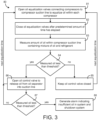
- Process 80 can be performed by one or more components of CO 2 refrigeration system 100. In some embodiments, process 80 is performed by controller 50, as described with reference to FIGS. 1-2 .
- Process 80 is shown to include opening oil equalization valves 37 connecting compressors 14 to compressor suction line 17 to equalize oil within each compressor 14 (step 81) and closing oil equalization valves 37 after a predetermined amount of time has elapsed (step 82).
- Step 81 may include opening oil equalization valves 37 simultaneously to allow oil from within each compressor 14 to flow through oil equalization lines 36 and into oil return line 33.
- oil equalization valves 37 are open, any excess oil within compressors 14 may flow into oil equalization lines 36 and into oil return line 33.
- Excess oil may include any oil within compressors 14 above the point at which oil equalization lines 37 connect to compressors 14. Any oil within compressors 14 below the connection point may remain in compressors 14.
- steps 81 and 82 are performed periodically (e.g., every ten minutes, every thirty minutes, etc.).
- the predetermined amount of time for which valves 37 are held open may be configurable and can be set to any desired value (e.g., ten seconds, five seconds, thirty seconds, etc.)
- Process 80 is shown to include measuring an amount of oil within a compressor suction line 17 containing a mixture of oil and refrigerant (step 83).
- Step 83 is performed by oil sensor 35.
- Oil sensor 35 can sense the amount of oil within suction line 17 and can provide an oil measurement to controller 50.
- step 83 is performed a predetermined amount of time (e.g., two minutes) after oil equalization valves 37 are opened and closed.
- process 80 may include waiting for two minutes (or any other amount of time) after step 82 is performed before advancing to step 83. This may allow the oil within suction line 17 to equilibrate before oil sensor 35 is used to measure the amount of oil.
- Process 80 is shown to include comparing the measured amount of oil to an oil threshold (step 84). If the measured amount of oil within suction line 17 is not less than the oil threshold (i.e., the measured amount of oil is greater than or equal to the oil threshold), controller 50 may cause oil control valve 39 to remain closed (step 85) and process 80 may return to step 81 at the next equalization time (e.g., after thirty minutes). However, if the measured amount of oil within suction line 17 is less than the oil threshold, controller 50 may cause oil control valve 39 to open to release oil from oil separator 31 and into suction line 17 via oil return line 33 (step 86).
- oil control valve 39 is held open for a predetermined amount of time (e.g., five seconds, ten seconds, etc.) and then closed. In other embodiments, oil control valve 39 is held open until the measured amount of oil reaches the oil threshold.
- a predetermined amount of time e.g., five seconds, ten seconds, etc.
- step 87 is performed a predetermined amount of time (e.g., two minutes) after oil control valve 39 is opened.
- process 80 may include waiting for two minutes (or any other amount of time) after step 86 is performed before advancing to step 87. This may allow the oil within suction line 17 to equilibrate before oil sensor 35 is used to measure the amount of oil.
- controller 50 may determine that there is sufficient oil in system 100 and process 80 may return to step 81. However, if the measured amount of oil within suction line 17 is less than the oil threshold, controller 50 may generate an alarm indicating insufficient oil and may shutdown system 100 (step 88). Process 80 may be repeated again at the next equalization time (e.g., thirty minutes later or at any other periodic interval).
- Coupled means the joining of two members directly or indirectly to one another. Such joining may be stationary (e.g., permanent) or moveable (e.g., removable or releasable). Such joining may be achieved with the two members or the two members and any additional intermediate members being integrally formed as a single unitary body with one another or with the two members or the two members and any additional intermediate members being attached to one another.
- the present disclosure contemplates methods, systems and program products on memory or other machine-readable media for accomplishing various operations.
- the embodiments of the present disclosure may be implemented using existing computer processors, or by a special purpose computer processor for an appropriate system, incorporated for this or another purpose, or by a hardwired system.
- Embodiments within the scope of the present disclosure include program products or memory including machine-readable media for carrying or having machine-executable instructions or data structures stored thereon.
- Such machine-readable media can be any available media that can be accessed by a general purpose or special purpose computer or other machine with a processor.
- machine-readable media can comprise RAM, ROM, EPROM, EEPROM, CD-ROM or other optical disk storage, magnetic disk storage or other magnetic storage devices, or any other medium which can be used to carry or store desired program code in the form of machine-executable instructions or data structures and which can be accessed by a general purpose or special purpose computer or other machine with a processor. Combinations of the above are also included within the scope of machine-readable media.
- Machine-executable instructions include, for example, instructions and data which cause a general purpose computer, special purpose computer, or special purpose processing machines to perform a certain function or group of functions.
Description
- The present disclosure relates generally to a refrigeration system and more particularly to a refrigeration system that uses carbon dioxide (i.e., CO2) as a refrigerant. The present disclosure relates more particularly still to a CO2 refrigeration system with an oil control system.
- Refrigeration systems are often used to provide cooling to temperature controlled display devices (e.g. cases, merchandisers, etc.) in supermarkets and other similar facilities. Vapor compression refrigeration systems are a type of refrigeration system which provides such cooling by circulating a fluid refrigerant (e.g., a liquid and/or vapor) through a thermodynamic vapor compression cycle. In a vapor compression cycle, the refrigerant is typically compressed to a high temperature high pressure state (e.g., by a compressor of the refrigeration system), cooled/condensed to a lower temperature state (e.g., in a gas cooler or condenser which absorbs heat from the refrigerant), expanded to a lower pressure (e.g., through an expansion valve), and evaporated to provide cooling by absorbing heat into the refrigerant. CO2 refrigeration systems are a type of vapor compression refrigeration system that use CO2 as a refrigerant.
- Some CO2 refrigeration systems include an oil management system which provides oil to one or more compressors of the refrigeration system. Oil management systems are typically either active or passive. Active oil control systems use an oil separator to remove oil from the refrigerant and then provide the oil directly to each compressor (e.g., via an oil line connecting the oil separator to each compressor). Passive oil control systems do not include an oil separator and allow the oil to remain mixed with the refrigerant throughout the refrigeration cycle.
-
EP1367259A1 describes a freezer system wherein if a refrigerating cycle has been formed, flow-rate adjusting valves are controlled in opening. When the temperature of refrigerant discharged rises above a preset value, a minimum opening for the flow-rate adjusting valves is changed to a value greater than a normal value. In particularEP1367259A1 shows a refrigeration system that provides cooling for a refrigeration load a refrigerant, the refrigeration system comprising:a plurality of compressors configured to circulate the refrigerant within the refrigeration system; a suction line configured to deliver the refrigerant to the plurality of compressors in parallel; an oil separator configured to separate oil from the refrigerant; and an oil return line configured to deliver the oil from the oil separator to the suction line, wherein the oil mixes with the refrigerant in the suction line before reaching the compressors. The refrigeration system ofEP1367259A1 further comprises an oil control valve located along the oil return line and configured to control a flow of oil from the oil separator to the suction line. - This section is intended to provide a background or context to the invention recited in the claims. The description herein may include concepts that could be pursued, but are not necessarily ones that have been previously conceived or pursued. Therefore, unless otherwise indicated herein, what is described in this section is not prior art and is not admitted to be prior art by inclusion in this section.
- One implementation of the present disclosure is a CO2 refrigeration system that provides cooling for a refrigeration load using carbon dioxide (CO2) as a refrigerant, in accordance with claim 1.
- In some embodiments, the CO2 refrigeration system includes a plurality of oil equalization lines and a plurality of oil equalization valves. Each of the oil equalization lines may connect one of the compressors to the oil return line. Each of the oil equalization valves may be located along one of the oil equalization lines and configured to control a flow of oil through the oil equalization lines.
- In some embodiments, the CO2 refrigeration system includes a controller configured to periodically open and close the plurality of oil equalization valves. Opening the oil equalization valves may cause any excess oil within the compressors to flow into the oil equalization lines and equalizes an amount of oil within each of the compressors.
- In some embodiments, the controller is configured to open the oil control valve in response to a determination that the measured amount of oil within the suction line is less than an oil threshold and keep the oil control valve closed in response to a determination that the measured amount of the oil within the suction line is greater than or equal to the oil threshold.
- Another implementation of the present disclosure is a method for operating a CO2 refrigeration system that provides cooling for a refrigeration load using carbon dioxide (CO2) as a refrigerant, in accordance with
claim 5. - In some embodiments, the method includes returning excess oil from the plurality of compressors to the oil return line via a plurality of oil equalization lines. Each oil equalization line may connect one of the compressors to the oil return line. The method may include operating a plurality of oil equalization valves to control a flow of the excess oil through the oil equalization lines. Each oil equalization valve may be located along one of the oil equalization lines.
- In some embodiments, the method includes periodically opening and closing the plurality of oil equalization valves. Opening the oil equalization valves may cause any excess oil within the compressors to flow into the oil equalization lines and may equalize an amount of oil within each of the compressors.
- In some embodiments, operating the oil control valve includes opening the oil control valve in response to a determination that the measured amount of oil within the suction line is less than an oil threshold and keeping the oil control valve closed in response to a determination that the measured amount of the oil within the suction line is greater than or equal to the oil threshold.
- Another implementation of the present disclosure is a controller for a CO2 refrigeration system that provides cooling for a refrigeration load using carbon dioxide (CO2) as a refrigerant. The controller includes one or more processors and one or more non-transitory computer-readable media storing instructions. When executed by the one or more processors, cause the one or more processors to perform operations including operating a plurality of compressors to circulate the CO2 refrigerant within the CO2 refrigeration system and obtaining a measurement of an amount of oil within a suction line coupled to an inlet of the compressors. The suction line contains a mixture of oil and the CO2 refrigerant. The operations include comparing the amount of oil within the suction line to an oil threshold and operating an oil control valve to control a flow of oil from an oil separator to the compressor suction line. The oil from the oil separator mixes with the CO2 refrigerant in the compressor suction line before reaching the compressors.
- In some embodiments, operating the oil control valve includes opening the oil control valve in response to a determination that the amount of oil within the suction line is less than the oil threshold and keeping the oil control valve closed in response to a determination that the amount of the oil within the suction line is greater than or equal to the oil threshold.
- In some embodiments, the operations include obtaining a second measurement of the amount of oil within the suction line after opening the oil control valve to release oil from the oil separator into the suction line and deactivating one or more components of the CO2 refrigeration system in response to the second measurement of the amount of oil within the suction line being less than the oil threshold.
- In some embodiments, the operations include opening a plurality of oil equalization valves connecting the plurality of compressors to an oil return line to equalize oil within each of the compressors and closing the plurality of oil equalization valves after a predetermined amount of time has elapsed.
- In some embodiments, opening the plurality of oil equalization valves causes any excess oil from the plurality of compressors to return to the oil return line via a plurality of oil equalization lines. Each oil equalization line may connect one of the compressors to the oil return line.
- In some embodiments, the oil return line receives both the flow of oil from the oil separator and a flow of oil from the oil equalization lines and delivers oil to the suction line.
- The foregoing is a summary and thus by necessity contains simplifications, generalizations, and omissions of detail. Consequently, those skilled in the art will appreciate that the summary is illustrative only and is not intended to be in any way limiting. Other aspects, inventive features, and advantages of the devices and/or processes described herein, as defined solely by the claims, will become apparent in the detailed description set forth herein and taken in conjunction with the accompanying drawings.
-
-
FIG. 1 is a block diagram of a CO2 refrigeration system that includes an semi-passive oil control system, according to an exemplary embodiment. -
FIG. 2 is a block diagram of a controller configured to control the CO2 refrigeration system and oil control system ofFIG. 1 , according to an exemplary embodiment. -
FIG. 3 is a flowchart of an oil control process which can be performed by the oil control system ofFIG. 1 and the controller ofFIG. 2 , according to an exemplary embodiment. - Referring generally to the FIGURES, a CO2 refrigeration system is shown, according to various exemplary embodiments. The CO2 refrigeration system may be a vapor compression refrigeration system which uses primarily carbon dioxide (i.e., CO2) as a refrigerant. In some implementations, the CO2 refrigeration system is used to provide cooling for temperature controlled display devices in a supermarket or other similar facility.
- The CO2 refrigeration system includes an oil control system. In some embodiments, the CO2 refrigeration system and/or the oil control system include some or all of the features described in
U.S. Provisional Patent Application No. 62/460,984 filed February 20, 2017 - In some embodiments, the oil control system includes several oil equalization lines, each of which connects a compressor of the CO2 refrigeration system to an oil return line. The oil equalization lines may connect to the compressors at connection points defining a target level of oil within each compressor. The oil control system may include oil equalization valves located along each oil equalization line. The oil equalization valves can be opened simultaneously to equalize the amount of oil within each compressor. When the oil equalization valves are open, any oil within the compressors above the connection points may flow into the oil equalization lines and into the oil return line, whereas any oil below the connection points may remain within the compressors. The oil return line then delivers any returned oil into the compressor suction line to mix with the refrigerant.
- The oil control system includes an oil sensor configured to measure an amount or level of oil within the compressor suction line. If the measured amount of oil in the suction line is less than an oil threshold after the oil equalization procedure has been performed (e.g., two minutes later), an oil control valve may be opened to release oil from the oil separator into the oil return line, which delivers the oil to the compressor suction line. However, if the measured amount of oil in the suction line is greater than or equal to the oil threshold, the oil control valve may remain closed. If the amount of oil in the suction line does not reach the oil threshold after opening the oil control valve, an alarm may be generated and the CO2 refrigeration system may be shutdown. These and other features of the CO2 refrigeration system and the oil control system are described in greater detail below.
- Referring now to
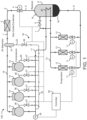
FIG. 1 , a CO2 refrigeration system 100 is shown, according to an exemplary embodiment. CO2 refrigeration system 100 may be a vapor compression refrigeration system which uses primarily carbon dioxide (CO2) as a refrigerant. However, it is contemplated that other refrigerants can be substituted for CO2 without departing from the teachings of the present disclosure. CO2 refrigeration system 100 and is shown to include a system of pipes, conduits, or other fluid channels (e.g.,fluid conduits condenser 2, ahigh pressure valve 4, areceiver 6,expansion valves 11,evaporators 12, andcompressors 14. - Gas cooler/
condenser 2 may be a heat exchanger or other similar device for removing heat from the CO2 refrigerant. Gas cooler/condenser 2 is shown receiving CO2 vapor from fluid conduit 1. In some embodiments, the CO2 vapor in fluid conduit 1 may have a pressure within a range from approximately 45 bar to approximately 100 bar (i.e., about 640 psig to about 1420 psig), depending on ambient temperature and other operating conditions. In some embodiments, gas cooler/condenser 2 may partially or fully condense CO2 vapor into liquid CO2 (e.g., if system operation is in a subcritical region). The condensation process may result in fully saturated CO2 liquid or a liquid-vapor mixture (e.g., having a thermodynamic quality between zero and one). In other embodiments, gas cooler/condenser 2 may cool the CO2 vapor (e.g., by removing superheat) without condensing the CO2 vapor into CO2 liquid (e.g., if system operation is in a supercritical region). In some embodiments, the cooling/condensation process is an isobaric process. Gas cooler/condenser 2 is shown outputting the cooled and/or condensed CO2 refrigerant intofluid conduit 3. -
High pressure valve 4 receives the cooled and/or condensed CO2 refrigerant fromfluid conduit 3 and outputs the CO2 refrigerant tofluid conduit 5.High pressure valve 4 may control the pressure of the CO2 refrigerant in gas cooler/condenser 2 by controlling an amount of CO2 refrigerant permitted to pass throughhigh pressure valve 4. In some embodiments,high pressure valve 4 is a high pressure thermal expansion valve (e.g., if the pressure influid conduit 3 is greater than the pressure in fluid conduit 5). In such embodiments,high pressure valve 4 may allow the CO2 refrigerant to expand to a lower pressure state. The expansion process may be an isenthalpic and/or adiabatic expansion process, resulting in a flash evaporation of the high pressure CO2 refrigerant to a lower pressure, lower temperature state. The expansion process may produce a liquid/vapor mixture (e.g., having a thermodynamic quality between zero and one). In some embodiments, the CO2 refrigerant expands to a pressure of approximately 38 bar (e.g., about 540 psig), which corresponds to a temperature of approximately 37° F. The CO2 refrigerant then flows fromfluid conduit 5 intoreceiver 6. -
Receiver 6 collects the CO2 refrigerant fromfluid conduit 5. In some embodiments,receiver 6 may be a flash tank or other fluid reservoir.Receiver 6 includes a CO2liquid portion 16 and a CO2 vapor portion 15 and may contain a partially saturated mixture of CO2 liquid and CO2 vapor. In some embodiments,receiver 6 separates the CO2 liquid from the CO2 vapor. The CO2 liquid may exitreceiver 6 throughfluid conduit 9.Fluid conduit 9 may be liquid headers leading toexpansion valves 11 andevaporators 12. The CO2 vapor may exitreceiver 6 throughfluid conduit 7.Fluid conduit 7 is shown leading the CO2 vapor tofluid conduit 13. - In various embodiments, any number of
expansion valves 11,evaporators 12, andcompressors 14 may be present.Expansion valves 11 may be electronic expansion valves or other similar expansion valves.Expansion valves 11 are shown receiving liquid CO2 refrigerant fromfluid conduit 9 and outputting the CO2 refrigerant toevaporators 12.Expansion valves 11 may cause the CO2 refrigerant to undergo a rapid drop in pressure, thereby expanding the CO2 refrigerant to a lower pressure, lower temperature state. In some embodiments,expansion valves 11 may expand the CO2 refrigerant to a pressure of approximately 30 bar. The expansion process may be an isenthalpic and/or adiabatic expansion process. -
Evaporators 12 are shown receiving the cooled and expanded CO2 refrigerant fromexpansion valves 11. In some embodiments,evaporators 12 may be associated with display cases/devices (e.g., if CO2 refrigeration system 100 is implemented in a supermarket setting).Evaporators 12 may be configured to facilitate the transfer of heat from the display cases/devices into the CO2 refrigerant. The added heat may cause the CO2 refrigerant to evaporate partially or completely. According to one embodiment, the CO2 refrigerant is fully evaporated inevaporators 12. In some embodiments, the evaporation process may be an isobaric process.Evaporators 12 are shown outputting the CO2 refrigerant intodischarge line 13, leading to aheat exchanger 20. -
Heat exchanger 20 may be positioned withinreceiver 6 and configured to transfer heat between the CO2 refrigerant enteringheat exchanger 20 fromdischarge line 13 and the CO2 refrigerant enteringreceiver 6 fromfluid conduit 5. In some embodiments,heat exchanger 20 precools the CO2 refrigerant withinreceiver 6 by transferring heat from the CO2 refrigerant surroundingheat exchanger 20 into the CO2 refrigerant withinheat exchanger 20. The CO2 refrigerant exitingheat exchanger 20 may pass intosuction line 17. In other embodiments,heat exchanger 20 can be omitted anddischarge line 13 may connect directly tosuction line 17.Suction line 17 may provide the CO2 refrigerant to compressors 14. -
Compressors 14 may compress the CO2 refrigerant into a superheated vapor having a pressure within a range of approximately 45 bar to approximately 100 bar. The output pressure fromcompressors 14 may vary depending on ambient temperature and other operating conditions. In some embodiments,compressors 14 operate in a transcritical mode. In operation, the CO2 discharge gas exitscompressors 14 and flows intodischarge line 19.Discharge line 19 is shown providing the CO2 refrigerant to anoil separator 31, which separates oil from the CO2 refrigerant. The CO2 refrigerant may exitoil separator 31 and flow through fluid conduit 1 into gas cooler/condenser 2. The oil separated from the CO2 refrigerant may flow into anoil return line 33. - Still referring to
FIG. 1 , CO2 refrigeration system 100 is shown to include agas bypass valve 8.Gas bypass valve 8 may receive the CO2 vapor from receiver 6 (via fluid conduit 7) and output the CO2 refrigerant intodischarge line 13. In some embodiments, the CO2 vapor that is bypassed throughgas bypass valve 8 is mixed with the CO2 refrigerant gas exiting evaporators 12 (e.g., via discharge line 13). The combined CO2 refrigerant gas may be provided to the suction side ofcompressors 14. In other embodiments,gas bypass valve 8 may output the CO2 refrigerant intosuction line 17.Compressors 14 may compress the CO2 vapor passing throughgas bypass valve 8 from a low pressure state (e.g., approximately 30 bar or lower) to a high pressure state (e.g., 45-100 bar). -
Gas bypass valve 8 may be operated to regulate or control the pressure within receiver 6 (e.g., by adjusting an amount of CO2 refrigerant permitted to pass through gas bypass valve 8). For example,gas bypass valve 8 may be adjusted (e.g., variably opened or closed) to adjust the mass flow rate, volume flow rate, or other flow rates of the CO2 refrigerant throughgas bypass valve 8.Gas bypass valve 8 may be opened and closed (e.g., manually, automatically, by acontroller 50, etc.) as needed to regulate the pressure withinreceiver 6. - In some embodiments,
gas bypass valve 8 includes a sensor for measuring a flow rate (e.g., mass flow, volume flow, etc.) of the CO2 refrigerant throughgas bypass valve 8. In other embodiments,gas bypass valve 8 includes an indicator (e.g., a gauge, a dial, etc.) from which the position ofgas bypass valve 8 may be determined. This position may be used to determine the flow rate of CO2 refrigerant throughgas bypass valve 8, as such quantities may be proportional or otherwise related. - In some embodiments,
gas bypass valve 8 may be a thermal expansion valve (e.g., if the pressure on the downstream side ofgas bypass valve 8 is lower than the pressure in fluid conduit 7). According to one embodiment, the pressure withinreceiver 6 is regulated bygas bypass valve 8 to a pressure of approximately 38 bar, which corresponds to about 37 °F. Advantageously, this pressure/temperature state may facilitate the use of copper tubing/piping for the downstream CO2 lines of the system. Additionally, this pressure/temperature state may allow such copper tubing to operate in a substantially frost-free manner. - Still referring to
FIG. 1 , CO2 refrigeration system 100 is shown to include anoil control system 30.Oil control system 30 can be configured to monitor and control the oil delivered tocompressors 14. In some embodiments, the oil control performed byoil control system 30 is semi-active or semi-passive. Active oil control systems typically use an oil separator to remove oil from the refrigerant and then provide the oil directly to each compressor (e.g., via an oil line connecting the oil separator to each compressor). Passive oil control systems typically do not include an oil separator and allow the oil to remain mixed with the refrigerant throughout the refrigeration cycle. Advantageously, the semi-active or semi-passive oil control performed byoil control system 30 may remove oil from the CO2 refrigerant, but does not provide the oil directly to eachcompressor 14. Rather, the oil is returned tosuction line 17 viaoil return line 33 and mixed with the CO2 refrigerant before the CO2 refrigerant is provided tocompressors 14. -
Oil control system 30 is shown to include anoil separator 31.Oil separator 31 may be configured to separate oil from the compressed CO2 refrigerant. In some embodiments,oil separator 31 is positioned downstream of compressors 14 (as shown inFIG. 1 ) such thatoil separator 31 receives the compressed CO2 refrigerant fromdischarge line 19.Oil separator 31 may remove oil from the compressed CO2 refrigerant and may deliver the compressed CO2 refrigerant into fluid conduit 1. In some embodiments, the oil separated from the CO2 refrigerant is collected inoil separator 31. For example, the oil can be stored in an internal reservoir withinoil separator 31. In other embodiments, the oil can be stored in an external reservoir separate fromoil separator 31. - The oil separated from the CO2 refrigerant by
oil separator 31 may exit the internal or external oil reservoir viaoil return line 33.Oil return line 33 connectsoil separator 31 and/or the oil reservoir tosuction line 17 where the oil mixes with the CO2 refrigerant. The refrigerant/oil mixture then feeds intocompressors 14. An oil control valve 39 (e.g., a solenoid valve) is positioned alongoil return line 33 and configured to control the flow of oil throughoil return line 33.Oil control valve 39 can be operated by controller 50 (described in greater detail below) to control the release of oil fromoil separator 31 intosuction line 17. - Unlike active oil control systems that provide oil directly to individual compressors,
oil control system 30 provides the oil into arefrigerant suction line 17 that feeds intomultiple compressors 14 in parallel. The oil may mix with the CO2 refrigerant insuction line 17 before reachingcompressors 14. The flow of oil back tocompressors 14 may be balanced such that eachcompressor 14 receives sufficient oil. - Still referring to
FIG. 1 ,oil control system 30 is shown to include severaloil equalization lines 36 andoil equalization valves 37. Eachoil equalization line 36 connects one ofcompressors 14 tooil return line 33 and is configured to deliver oil and/or CO2 refrigerant from the correspondingcompressor 14 intooil return line 33. In some embodiments,oil equalization lines 36 are connected to the crank casings ofcompressors 14.Oil equalization lines 36 may connect tocompressors 14 at connection points corresponding to the desired oil level (e.g., the maximum allowable oil level or maximum desirable oil level) within each ofcompressors 14. Accordingly, any oil withincompressors 14 above the desired oil level (i.e., above the connection point) can flow intooil equalization lines 36 whenvalves 37 are opened, whereas any oil withincompressors 14 below the desired oil level (i.e., below the connection point) may remain withincompressors 14 whenvalves 37 are opened. - Each
oil equalization valve 37 may be positioned along one ofoil equalization lines 36 and can be operated (e.g., by controller 50) to control the flow of oil through the correspondingoil equalization line 36. In some embodiments,oil equalization valves 37 are periodically opened and closed bycontroller 50 to equalize the amount of oil within each ofcompressors 14. For example, whencompressors 14 are running, alloil equalization valves 37 may be opened simultaneously for a predetermined amount of time (e.g., ten seconds) and subsequently closed after the predetermined amount of time has elapsed. If the oil level within any ofcompressors 14 is above the connection point, any oil above the connection point may flow intooil equalization lines 36, throughoil equalization valves 37, and intooil return line 33 whilevalves 37 are open. If the level of oil within any ofcompressors 14 is below the connection point, anysuch compressors 14 may return only CO2 refrigerant gas throughoil equalization lines 36 whenvalves 37 are opened. In this way, the level of oil within each ofcompressors 14 is equalized. The process of opening and closingoil equalization valves 37 to equalize the amount of oil withincompressors 14 is referred to herein as an oil equitation procedure. -
Oil control system 30 includes anoil sensor 35.Oil sensor 35 may be located alongsuction line 17 and configured to measure the amount of oil within the refrigerant/oil mixture insuction line 17.Oil sensor 35 can be any of a variety of sensor types (e.g., optical, capacitive, dielectrical, resonance frequency, floating bulb, etc.) configured to sense the amount of oil in the refrigerant/oil mixture insuction line 17. In some embodiments,oil sensor 35 uses a frequency sweep technique to sense oil, either as a mist or as a liquid oil level, withinsuction line 17. For example,oil sensor 35 may be a Baumer frequency sweep sensor configured to sense the amount of oil in the oil/refrigerant mixture withinsuction line 17. - In some embodiments,
oil sensor 35 is used to sense the amount of oil withinsuction line 17 shortly after the oil equalization procedure is performed. For example,oil sensor 35 may sense the amount of oil withinsuction line 17 approximately two minutes (or any other amount of time) after the oil equalization procedure is performed.Controller 50 may compare the oil measurement fromoil sensor 35 with a threshold oil value. If the oil measurement is greater than or equal to the threshold oil value (i.e., the amount of oil withinsuction line 17 is above the threshold),controller 50 may causeoil control valve 39 to remain closed. However, if the oil measurement is less than the threshold oil value (i.e., the amount of oil withinsuction line 17 is below a threshold),controller 50 may causeoil control valve 39 to open for a predetermined amount of time (e.g., five seconds) to allow oil fromoil separator 31 to flow intooil return line 33. In other embodiments,oil control valve 39 can be held open until the oil measurement obtained byoil sensor 35 reaches the threshold oil value rather than closing oil control valve after the predetermined amount of time has elapsed. - If the oil measurement from
oil sensor 35 fails to reach the threshold oil value after openingoil control valve 39,controller 50 may generate an alarm indicating that insufficient oil is present withinoil control system 30. Upon generating the alarm,controller 50 may automatically stop the operation of CO2 refrigeration system 100 (e.g., by stopping compressors 14) to prevent any damage that could be caused by insufficient oil. - Referring now to
FIG. 2 , a blockdiagram illustrating controller 50 in greater detail is shown, according to an exemplary embodiment.Controller 50 may receive signals from one or more measurement devices (e.g., pressure sensors, temperature sensors, flow sensors, etc.) located within CO2 refrigeration system 100. For example,controller 50 is shown receiving an oil measurement fromoil sensor 35.Controller 50 may also receive a compressor state signal from one or more ofcompressors 14. The compressor state signals may indicate which ofcompressors 14 are running and which ofcompressors 14 are not running.Controller 50 may use the oil measurement and the compressor states to determine appropriate control actions for control devices of CO2 refrigeration system 100 (e.g.,compressors 14,valves - In some embodiments,
controller 50 is configured to operategas bypass valve 8 to maintain the CO2 pressure withinreceiver 6 at a desired setpoint or within a desired range. In some embodiments,controller 50 operatesgas bypass valve 8 based on the temperature of the CO2 refrigerant at the outlet of gas cooler/condenser 2. In other embodiments,controller 50 operatesgas bypass valve 8 based a flow rate (e.g., mass flow, volume flow, etc.) of CO2 refrigerant throughgas bypass valve 8.Controller 50 may use a valve position ofgas bypass valve 8 as a proxy for CO2 refrigerant flow rate. In some embodiments,controller 50 operateshigh pressure valve 4 andexpansion valves 11 to regulate the flow of refrigerant insystem 100. In some embodiments,controller 50 operatesvalves oil control system 30. -
Controller 50 may include feedback control functionality for adaptively operating the various components of CO2 refrigeration system 100. For example,controller 50 may receive a setpoint (e.g., a temperature setpoint, a pressure setpoint, a flow rate setpoint, a power usage setpoint, etc.) and operate one or more components ofsystem 100 to achieve the setpoint. The setpoint may be specified by a user (e.g., via a user input device, a graphical user interface, a local interface, a remote interface, etc.) or automatically determined bycontroller 50 based on a history of data measurements. In some embodiments,controller 50 includes some or all of the features of the controller described in P.C.T. Patent Application No.PCT/US2016/044164 filed July 27, 2016 , and/orU.S. Provisional Patent Application No. 62/460,984 filed February 20, 2017 -
Controller 50 may be a proportional-integral (PI) controller, a proportional-integral-derivative (PID) controller, a pattern recognition adaptive controller (PRAC), a model recognition adaptive controller (MRAC), a model predictive controller (MPC), or any other type of controller employing any type of control functionality. In some embodiments,controller 50 is a local controller for CO2 refrigeration system 100. In other embodiments,controller 50 is a supervisory controller for a plurality of controlled subsystems (e.g., a refrigeration system, an AC system, a lighting system, a security system, etc.). For example,controller 50 may be a controller for a comprehensive building management system incorporating CO2 refrigeration system 100.Controller 50 may be implemented locally, remotely, or as part of a cloud-hosted suite of building management applications. - Still referring to
FIG. 2 ,controller 50 is shown to include acommunications interface 52 and aprocessing circuit 60. Communications interface 52 can be or include wired or wireless interfaces (e.g., jacks, antennas, transmitters, receivers, transceivers, wire terminals, etc.) for conducting electronic data communications. For example,communications interface 52 may be used to conduct communications withgas bypass valve 8,oil sensor 35,compressors 14,valves high pressure valve 4, various data acquisition devices within CO2 refrigeration system 100 (e.g., temperature sensors, pressure sensors, flow sensors, etc.) and/or other external devices or data sources. Data communications may be conducted via a direct connection (e.g., a wired connection, an ad-hoc wireless connection, etc.) or a network connection (e.g., an Internet connection, a LAN, WAN, or WLAN connection, etc.). For example,communications interface 52 can include an Ethernet card and port for sending and receiving data via an Ethernet-based communications link or network. In another example,communications interface 52 can include a Wi-Fi transceiver or a cellular or mobile phone transceiver for communicating via a wireless communications network. - Processing
circuit 60 is shown to include aprocessor 62 andmemory 70.Processor 62 can be implemented as a general purpose processor, an application specific integrated circuit (ASIC), one or more field programmable gate arrays (FPGAs), a group of processing components, a microcontroller, or other suitable electronic processing components. Memory 70 (e.g., memory device, memory unit, storage device, etc.) may be one or more devices (e.g., RAM, ROM, solid state memory, hard disk storage, etc.) for storing data and/or computer code for completing or facilitating the various processes, layers and modules described in the present application.Memory 70 may be or include volatile memory or non-volatile memory.Memory 70 may include database components, object code components, script components, or any other type of information structure for supporting the various activities and information structures described in the present application. According to an exemplary embodiment,memory 70 is communicably connected toprocessor 62 viaprocessing circuit 60 and includes computer code for executing (e.g., by processingcircuit 60 and/or processor 62) one or more processes or control features described herein. - Still referring to
FIG. 2 ,controller 50 is shown to include anoil detector 72 and acompressor state detector 74.Oil detector 72 can be configured to detect the level or amount of oil withinsuction line 17 based on the oil measurement fromoil sensor 35. For example,oil detector 72 can determine whether the amount or level of oil within the oil/refrigerant mixture insuction line 17 exceeds a threshold oil level.Compressor state detector 74 can be configured to detect the state of each ofcompressors 14. For example,compressor state detector 74 can determine whether each ofcompressors 14 is currently running or not running. -
Controller 50 is shown to include avalve controller 76.Valve controller 76 may receive input fromoil detector 72 indicating the current oil amount or level withinsuction line 17.Valve controller 76 may also receive input fromcompressor state detector 74 indicating the current state of each ofcompressors 14.Valve controller 76 can generate control signals for one or more ofvalves compressors 14. - In some embodiments,
valve controller 76 causesoil equalization valves 37 to open and close periodically. For example,valve controller 76 can causeoil equalization valves 37 to open for a predetermined amount of time (e.g., ten seconds) at a periodic interval (e.g., every thirty minutes). The predetermined amount of time and the periodic interval are adjustable and can be set to any amount of time, as may be desirable in various implementations. In some embodiments,valve controller 76 causes all ofoil equalization valves 37 to open simultaneously. After the predetermined amount of time has expired,valve controller 76 may causeoil equalization valves 37 to close simultaneously. As described above, opening and closingoil equalization valves 37 may equalize the amount of oil within each ofcompressors 14. - In some embodiments,
valve controller 76 uses the oil measurement fromoil sensor 35 to generate control signals foroil control valve 39. For example,valve controller 76 can compare the oil measurement fromoil sensor 35 to an oil threshold.Valve controller 76 may openoil control valve 39 in response to a determination that the amount of oil withinsuction line 17 is less than the oil threshold. Openingoil control valve 39 may cause oil to be dispensed fromoil separator 31 and flow intosuction line 17 viaoil return line 33. However, if the amount of oil withinsuction line 17 is greater than or equal to the oil threshold,valve controller 76 may causeoil control valve 39 to remain closed. - Referring now to
FIG. 3 , a block diagram of anoil control process 80 is shown, according to an exemplary embodiment.Process 80 can be performed by one or more components of CO2 refrigeration system 100. In some embodiments,process 80 is performed bycontroller 50, as described with reference toFIGS. 1-2 . -
Process 80 is shown to include openingoil equalization valves 37 connectingcompressors 14 tocompressor suction line 17 to equalize oil within each compressor 14 (step 81) and closingoil equalization valves 37 after a predetermined amount of time has elapsed (step 82).Step 81 may include openingoil equalization valves 37 simultaneously to allow oil from within eachcompressor 14 to flow throughoil equalization lines 36 and intooil return line 33. Whenoil equalization valves 37 are open, any excess oil withincompressors 14 may flow intooil equalization lines 36 and intooil return line 33. Excess oil may include any oil withincompressors 14 above the point at whichoil equalization lines 37 connect to compressors 14. Any oil withincompressors 14 below the connection point may remain incompressors 14. In some embodiments, steps 81 and 82 are performed periodically (e.g., every ten minutes, every thirty minutes, etc.). The predetermined amount of time for whichvalves 37 are held open may be configurable and can be set to any desired value (e.g., ten seconds, five seconds, thirty seconds, etc.) -
Process 80 is shown to include measuring an amount of oil within acompressor suction line 17 containing a mixture of oil and refrigerant (step 83).Step 83 is performed byoil sensor 35.Oil sensor 35 can sense the amount of oil withinsuction line 17 and can provide an oil measurement tocontroller 50. In some embodiments,step 83 is performed a predetermined amount of time (e.g., two minutes) afteroil equalization valves 37 are opened and closed. For example,process 80 may include waiting for two minutes (or any other amount of time) afterstep 82 is performed before advancing to step 83. This may allow the oil withinsuction line 17 to equilibrate beforeoil sensor 35 is used to measure the amount of oil. -
Process 80 is shown to include comparing the measured amount of oil to an oil threshold (step 84). If the measured amount of oil withinsuction line 17 is not less than the oil threshold (i.e., the measured amount of oil is greater than or equal to the oil threshold),controller 50 may causeoil control valve 39 to remain closed (step 85) andprocess 80 may return to step 81 at the next equalization time (e.g., after thirty minutes). However, if the measured amount of oil withinsuction line 17 is less than the oil threshold,controller 50 may causeoil control valve 39 to open to release oil fromoil separator 31 and intosuction line 17 via oil return line 33 (step 86). In some embodiments,oil control valve 39 is held open for a predetermined amount of time (e.g., five seconds, ten seconds, etc.) and then closed. In other embodiments,oil control valve 39 is held open until the measured amount of oil reaches the oil threshold. - After opening
oil control valve 39, the amount of oil withinsuction line 17 can be measured again and compared with the oil threshold (step 87). In some embodiments,step 87 is performed a predetermined amount of time (e.g., two minutes) afteroil control valve 39 is opened. For example,process 80 may include waiting for two minutes (or any other amount of time) afterstep 86 is performed before advancing to step 87. This may allow the oil withinsuction line 17 to equilibrate beforeoil sensor 35 is used to measure the amount of oil. - If the measured amount of oil within
suction line 17 is not less than the oil threshold (i.e., the measured amount of oil is greater than or equal to the oil threshold),controller 50 may determine that there is sufficient oil insystem 100 andprocess 80 may return to step 81. However, if the measured amount of oil withinsuction line 17 is less than the oil threshold,controller 50 may generate an alarm indicating insufficient oil and may shutdown system 100 (step 88).Process 80 may be repeated again at the next equalization time (e.g., thirty minutes later or at any other periodic interval). - The construction and arrangement of the CO2 refrigeration system as shown in the various exemplary embodiments are illustrative only. Although only a few embodiments have been described in detail in this disclosure, those skilled in the art who review this disclosure will readily appreciate that many modifications are possible (e.g., variations in sizes, dimensions, structures, shapes and proportions of the various elements, values of parameters, mounting arrangements, use of materials, colors, orientations, etc.) without materially departing from the novel teachings and advantages of the subject matter described herein. For example, elements shown as integrally formed may be constructed of multiple parts or elements, the position of elements may be reversed or otherwise varied, and the nature or number of discrete elements or positions may be altered or varied. The order or sequence of any process or method steps may be varied or re-sequenced according to alternative embodiments. Other substitutions, modifications, changes and omissions may also be made in the design, operating conditions and arrangement of the various exemplary embodiments without departing from the scope of the present invention. Further, it is contemplated that any of the embodiments, implementations, features, or other details described herein can be combined or used in any combination with each other without departing from the scope of the present invention.
- As utilized herein, the terms "approximately," "about," "substantially", and similar terms are intended to have a broad meaning in harmony with the common and accepted usage by those of ordinary skill in the art to which the subject matter of this disclosure pertains. It should be understood by those of skill in the art who review this disclosure that these terms are intended to allow a description of certain features described and claimed without restricting the scope of these features to the precise numerical ranges provided. Accordingly, these terms should be interpreted as indicating that insubstantial or inconsequential modifications or alterations of the subject matter described and claimed are considered to be within the scope of the invention as recited in the appended claims.
- It should be noted that the term "exemplary" as used herein to describe various embodiments is intended to indicate that such embodiments are possible examples, representations, and/or illustrations of possible embodiments (and such term is not intended to connote that such embodiments are necessarily extraordinary or superlative examples).
- The terms "coupled," "connected," and the like as used herein mean the joining of two members directly or indirectly to one another. Such joining may be stationary (e.g., permanent) or moveable (e.g., removable or releasable). Such joining may be achieved with the two members or the two members and any additional intermediate members being integrally formed as a single unitary body with one another or with the two members or the two members and any additional intermediate members being attached to one another.
- References herein to the positions of elements (e.g., "top," "bottom," "above," "below," etc.) are merely used to describe the orientation of various elements in the FIGURES. It should be noted that the orientation of various elements may differ according to other exemplary embodiments, and that such variations are intended to be encompassed by the present disclosure.
- The present disclosure contemplates methods, systems and program products on memory or other machine-readable media for accomplishing various operations. The embodiments of the present disclosure may be implemented using existing computer processors, or by a special purpose computer processor for an appropriate system, incorporated for this or another purpose, or by a hardwired system. Embodiments within the scope of the present disclosure include program products or memory including machine-readable media for carrying or having machine-executable instructions or data structures stored thereon. Such machine-readable media can be any available media that can be accessed by a general purpose or special purpose computer or other machine with a processor. By way of example, such machine-readable media can comprise RAM, ROM, EPROM, EEPROM, CD-ROM or other optical disk storage, magnetic disk storage or other magnetic storage devices, or any other medium which can be used to carry or store desired program code in the form of machine-executable instructions or data structures and which can be accessed by a general purpose or special purpose computer or other machine with a processor. Combinations of the above are also included within the scope of machine-readable media. Machine-executable instructions include, for example, instructions and data which cause a general purpose computer, special purpose computer, or special purpose processing machines to perform a certain function or group of functions.
- Although the figures may show a specific order of method steps, the order of the steps may differ from what is depicted. Also two or more steps may be performed concurrently or with partial concurrence. Such variation will depend on the software and hardware systems chosen and on designer choice. All such variations are within the scope of the disclosure. Likewise, software implementations could be accomplished with standard programming techniques with rule based logic and other logic to accomplish the various connection steps, processing steps, comparison steps and decision steps.
Claims (9)
- A CO2 refrigeration system (100) that provides cooling for a refrigeration load using carbon dioxide (CO2) as a refrigerant, the CO2 refrigeration system (100) comprising:a plurality of compressors (14) configured to circulate the CO2 refrigerant within the CO2 refrigeration system (100);a suction line (17) configured to deliver the CO2 refrigerant to the plurality of compressors (14) in parallel;an oil separator (31) configured to separate oil from the CO2 refrigerant;an oil return line (33) configured to deliver the oil from the oil separator (31) to the suction line (17), wherein the oil mixes with the CO2 refrigerant in the suction line (17) before reaching the compressors (14);an oil control valve (39) located along the oil return line (33) and configured to control a flow of oil from the oil separator (31) to the suction line (17);an oil sensor (35) configured to measure an amount of oil within the suction line (17); anda controller (50) configured to open and close the oil control valve (39) based on the measured amount of oil within the suction line (17);wherein the oil is permitted to flow from the oil separator (31) to the suction line (17) when the oil control valve (39) is open and prevented from flowing from the oil separator (31) to the suction line (17) when the oil control valve (39) is closed.
- The CO2 refrigeration system (100) of Claim 1, further comprising:a plurality of oil equalization lines (36), each connecting one of the compressors (14) to the oil return line (33), wherein excess oil within the compressors (14) returns to the oil return line (33) via the plurality of oil equalization lines (36); and optionallya plurality of oil equalization valves (37), each located along one of the oil equalization lines (36) and configured to control a flow of oil through the oil equalization lines (36).
- The CO2 refrigeration system (100) of Claim 2, further comprising a controller (50) configured to periodically open and close the plurality of oil equalization valves (37);
wherein opening the oil equalization valves (37) causes any excess oil within the compressors (14) to flow into the oil equalization lines (36) and equalizes an amount of oil within each of the compressors (14). - The CO2 refrigeration system (100) of any of Claims 1 to 3, wherein the controller (50) is configured to:open the oil control valve (39) in response to a determination that the measured amount of oil within the suction line (17) is less than an oil threshold; andkeep the oil control valve (39) closed in response to a determination that the measured amount of the oil within the suction line (17) is greater than or equal to the oil threshold.
- A method (80) for operating a CO2 refrigeration system (100) that provides cooling for a refrigeration load using carbon dioxide (CO2) as a refrigerant, the method (80) comprising:Operating a plurality of compressors (14) to circulate the CO2 refrigerant within the CO2 refrigeration system (100);delivering the CO2 refrigerant to the compressors (14) via a suction line (17) coupled in parallel to an inlet of each of the plurality of compressors (14);separating oil from the CO2 refrigerant at an oil separator (31) coupled to an outlet of the compressors (14) via a discharge line (13);delivering the oil from the oil separator (31) to the suction line (17) via an oil return line (33), wherein the oil mixes with the CO2 refrigerant in the suction line (17) before reaching the compressors (14);operating an oil control valve (39) located along the oil return line (33) to control a flow of oil from the oil separator (31) to the suction line (17); andmeasuring an amount of oil within the suction line (17) via an oil sensor (35) coupled to the suction line (17);wherein operating the oil control valve (39) comprises opening and closing the oil control valve (39) based on the measured amount of oil within the suction line (17); andwherein the oil is permitted to flow from the oil separator (31) to the suction line (17) when the oil control valve (39) is open and prevented from flowing from the oil separator (31) to the suction line (17) when the oil control valve (39) is closed.
- The method (80) of Claim 5, further comprising:returning excess oil from the plurality of compressors (14) to the oil return line (33) via a plurality of oil equalization lines (36), each oil equalization line (36) connecting one of the compressors (14) to the oil return line (33); and optionallyoperating a plurality of oil equalization valves (37) to control a flow of the excess oil through the oil equalization lines (36), each oil equalization valve (37) located along one of the oil equalization lines (36).
- The method (80) of Claim 6, further comprising periodically opening and closing the plurality of oil equalization valves (37);
wherein opening the oil equalization valves (37) causes any excess oil within the compressors (14) to flow into the oil equalization lines (36) and equalizes an amount of oil within each of the compressors (14). - The method (80) of any of Claims 5 to 7, wherein operating the oil control valve (39) comprises:opening the oil control valve (39) in response to a determination that the measured amount of oil within the suction line (17) is less than an oil threshold; andkeeping the oil control valve (39) closed in response to a determination that the measured amount of the oil within the suction line (17) is greater than or equal to the oil threshold.
- The method (80) of Claim 8, further comprising:obtaining a second measurement of the amount of oil within the suction line (17) after opening the oil control valve (39) to release oil from the oil separator (31) into the suction line (17); anddeactivating one or more components of the CO2 refrigeration system (100) in response to the second measurement of the amount of oil within the suction line (17) being less than the oil threshold.
Applications Claiming Priority (1)
| Application Number | Priority Date | Filing Date | Title |
|---|---|---|---|
| US201862675868P | 2018-05-24 | 2018-05-24 |
Related Child Applications (1)
| Application Number | Title | Priority Date | Filing Date |
|---|---|---|---|
| EP24156936.7 Division-Into | 2024-02-09 |
Publications (2)
| Publication Number | Publication Date |
|---|---|
| EP3572741A1 EP3572741A1 (en) | 2019-11-27 |
| EP3572741B1 true EP3572741B1 (en) | 2024-03-27 |
Family
ID=66647083
Family Applications (1)
| Application Number | Title | Priority Date | Filing Date |
|---|---|---|---|
| EP19176127.9A Active EP3572741B1 (en) | 2018-05-24 | 2019-05-23 | Refrigeration system with oil control system |
Country Status (4)
| Country | Link |
|---|---|
| US (2) | US11796227B2 (en) |
| EP (1) | EP3572741B1 (en) |
| CA (1) | CA3044005A1 (en) |
| MX (1) | MX2019006023A (en) |
Families Citing this family (3)
| Publication number | Priority date | Publication date | Assignee | Title |
|---|---|---|---|---|
| CN112113361B (en) * | 2020-09-09 | 2022-04-15 | 北京航空航天大学 | Isothermal compression efficient refrigerating device and method thereof |
| US11788779B2 (en) | 2020-09-25 | 2023-10-17 | Carrier Corporation | Multi-compressor oil equalization |
| US20230076487A1 (en) * | 2021-09-07 | 2023-03-09 | Hill Phoenix, Inc. | Oil management in refrigeration systems |
Citations (2)
| Publication number | Priority date | Publication date | Assignee | Title |
|---|---|---|---|---|
| EP1367259A1 (en) * | 2001-02-15 | 2003-12-03 | Toshiba Carrier Corporation | Freezer |
| EP1443286A1 (en) * | 2001-10-19 | 2004-08-04 | Toshiba Carrier Corporation | Refrigerating equipment |
Family Cites Families (75)
| Publication number | Priority date | Publication date | Assignee | Title |
|---|---|---|---|---|
| US4270363A (en) | 1979-04-16 | 1981-06-02 | Schneider Metal Manufacturing Company | Refrigerating machine including energy conserving heat exchange apparatus |
| US4589263A (en) | 1984-04-12 | 1986-05-20 | Hussmann Corporation | Multiple compressor oil system |
| US4827789A (en) | 1984-06-26 | 1989-05-09 | Western Gear Corporation | Linear actuator |
| JPS63177684U (en) * | 1987-05-07 | 1988-11-17 | ||
| US5369958A (en) * | 1992-10-15 | 1994-12-06 | Mitsubishi Denki Kabushiki Kaisha | Air conditioner |
| US5425246A (en) | 1994-03-03 | 1995-06-20 | General Electric Company | Refrigerant flow rate control based on evaporator dryness |
| CN1152217C (en) * | 1994-06-29 | 2004-06-02 | 达金工业株式会社 | Oil balancing operation control device for air conditioner |
| US5539382A (en) | 1995-04-21 | 1996-07-23 | Carrier Corporation | System for monitoring the operation of a condenser unit |
| US6385980B1 (en) | 2000-11-15 | 2002-05-14 | Carrier Corporation | High pressure regulation in economized vapor compression cycles |
| US6418735B1 (en) | 2000-11-15 | 2002-07-16 | Carrier Corporation | High pressure regulation in transcritical vapor compression cycles |
| US6415611B1 (en) | 2001-02-22 | 2002-07-09 | Praxair Technology, Inc. | Cryogenic refrigeration system using magnetic refrigerator forecooling |
| JP3966044B2 (en) | 2002-04-02 | 2007-08-29 | 株式会社デンソー | Air conditioner |
| US7065979B2 (en) | 2002-10-30 | 2006-06-27 | Delaware Capital Formation, Inc. | Refrigeration system |
| JP2004257694A (en) | 2003-02-27 | 2004-09-16 | Denso Corp | Vapor compression type refrigerator |
| JP2005024210A (en) | 2003-07-01 | 2005-01-27 | Denso Corp | Vapor compression type refrigerating machine |
| JP2005037093A (en) | 2003-07-18 | 2005-02-10 | Tgk Co Ltd | Refrigerating cycle |
| CN1291196C (en) | 2004-02-18 | 2006-12-20 | 株式会社电装 | Ejector cycle having multiple evaporators |
| US20050217278A1 (en) | 2004-03-31 | 2005-10-06 | Mongia Rajiv K | Apparatus to use a magnetic based refrigerator in mobile computing device |
| US7010925B2 (en) | 2004-06-07 | 2006-03-14 | Carrier Corporation | Method of controlling a carbon dioxide heat pump water heating system |
| CN100507402C (en) | 2004-08-09 | 2009-07-01 | 卡里尔公司 | CO2 refrigeration circuit with sub-cooling of the liquid refrigerant against the receiver flash gas and method for operating the same |
| WO2006015629A1 (en) | 2004-08-09 | 2006-02-16 | Carrier Corporation | Flashgas removal from a receiver in a refrigeration circuit |
| WO2006038354A1 (en) | 2004-09-30 | 2006-04-13 | Mayekawa Mfg. Co., Ltd | Ammonia/co2 refrigeration system |
| CN100520225C (en) | 2005-02-18 | 2009-07-29 | 卡里尔公司 | Method for controlling high-pressure in an intermittently supercritically operating refrigeration circuit |
| MX2007010002A (en) | 2005-02-18 | 2008-03-19 | Carrier Corp | Refrigeration circuit with improved liquid/vapour receiver. |
| US20090120108A1 (en) | 2005-02-18 | 2009-05-14 | Bernd Heinbokel | Co2-refrigerant device with heat reclaim |
| US8011192B2 (en) | 2005-06-23 | 2011-09-06 | Hill Phoenix, Inc. | Method for defrosting an evaporator in a refrigeration circuit |
| JP4592616B2 (en) | 2006-02-27 | 2010-12-01 | 三洋電機株式会社 | Refrigeration cycle equipment |
| US20080006044A1 (en) | 2006-07-10 | 2008-01-10 | Ziming Tan | Method for controlling temperature |
| JP2008064439A (en) | 2006-09-11 | 2008-03-21 | Daikin Ind Ltd | Air conditioner |
| CN101583834B (en) | 2006-10-26 | 2011-06-29 | 江森自控科技公司 | Economized refrigeration system |
| NO327832B1 (en) | 2007-06-29 | 2009-10-05 | Sinvent As | Steam circuit compression dress system with closed circuit as well as method for operating the system. |
| US10254025B2 (en) | 2007-10-10 | 2019-04-09 | Carrier Corporation | Refrigerating system and method for controlling the same |
| DK2220450T4 (en) | 2007-11-09 | 2023-02-20 | Carrier Corp | TRANSPORT REFRIGERATION SYSTEM AND METHOD FOR USING THEREOF |
| WO2009086493A2 (en) | 2007-12-28 | 2009-07-09 | Johnson Controls Technology Company | Vapor compression system |
| US9151521B2 (en) | 2008-04-22 | 2015-10-06 | Hill Phoenix, Inc. | Free cooling cascade arrangement for refrigeration system |
| US7913506B2 (en) | 2008-04-22 | 2011-03-29 | Hill Phoenix, Inc. | Free cooling cascade arrangement for refrigeration system |
| JP5181813B2 (en) | 2008-05-02 | 2013-04-10 | ダイキン工業株式会社 | Refrigeration equipment |
| GB2460726B (en) | 2008-06-13 | 2012-05-16 | Arctic Circle Ltd | A Refrigeration System with an Oil Reservoir Header |
| US8631666B2 (en) | 2008-08-07 | 2014-01-21 | Hill Phoenix, Inc. | Modular CO2 refrigeration system |
| WO2010021137A1 (en) * | 2008-08-22 | 2010-02-25 | パナソニック株式会社 | Freeze cycling device |
| WO2010036480A2 (en) | 2008-09-29 | 2010-04-01 | Carrier Corporation | Flash tank economizer cycle control |
| CA2820930C (en) | 2008-10-23 | 2016-04-26 | Serge Dube | Co2 refrigeration system |
| GB2469616B (en) | 2009-02-11 | 2013-08-28 | Star Refrigeration | A refrigeration system operable under transcritical conditions |
| JP2010216685A (en) | 2009-03-13 | 2010-09-30 | Daikin Ind Ltd | Heat pump system |
| WO2010117973A2 (en) | 2009-04-09 | 2010-10-14 | Carrier Corporation | Refrigerant vapor compression system with hot gas bypass |
| CN105157266B (en) | 2009-10-23 | 2020-06-12 | 开利公司 | Operation of refrigerant vapor compression system |
| DK2504641T3 (en) | 2009-11-25 | 2019-02-25 | Carrier Corp | PROTECTION FROM LOW SUCTION PRESSURE IN COOLING STEAM COMPRESSION SYSTEM |
| CA2820869A1 (en) | 2009-12-08 | 2011-06-16 | Get Green Energy Corporation | Heat pump |
| US9752801B2 (en) | 2010-07-23 | 2017-09-05 | Carrier Corporation | Ejector cycle |
| CA2724255C (en) | 2010-09-28 | 2011-09-13 | Serge Dube | Co2 refrigeration system for ice-playing surfaces |
| US9541311B2 (en) | 2010-11-17 | 2017-01-10 | Hill Phoenix, Inc. | Cascade refrigeration system with modular ammonia chiller units |
| US9664424B2 (en) | 2010-11-17 | 2017-05-30 | Hill Phoenix, Inc. | Cascade refrigeration system with modular ammonia chiller units |
| US9657977B2 (en) | 2010-11-17 | 2017-05-23 | Hill Phoenix, Inc. | Cascade refrigeration system with modular ammonia chiller units |
| CA2735347C (en) | 2011-03-28 | 2011-10-11 | Serge Dube | Co2 refrigeration system for ice-playing surface |
| DK177329B1 (en) | 2011-06-16 | 2013-01-14 | Advansor As | Refrigeration system |
| US9395112B2 (en) | 2011-07-05 | 2016-07-19 | Danfoss A/S | Method for controlling operation of a vapour compression system in a subcritical and a supercritical mode |
| US9395105B2 (en) | 2011-09-01 | 2016-07-19 | Mitsubishi Electric Corporation | Refrigeration cycle device |
| KR20130041640A (en) | 2011-10-17 | 2013-04-25 | 엘지전자 주식회사 | Air conditioner and control method of the same |
| US9377236B2 (en) | 2011-11-21 | 2016-06-28 | Hilll Phoenix, Inc. | CO2 refrigeration system with hot gas defrost |
| WO2013084301A1 (en) | 2011-12-06 | 2013-06-13 | 三菱電機株式会社 | Heat pump type heating/hot-water supply system |
| CA2766361A1 (en) | 2012-01-30 | 2013-07-30 | Serge Dube | Co2 refrigeration system for ice-playing surface |
| CA2771113A1 (en) | 2012-03-08 | 2012-05-22 | Serge Dube | Co2 refrigeration system for ice-playing surface |
| JP5288020B1 (en) | 2012-03-30 | 2013-09-11 | ダイキン工業株式会社 | Refrigeration equipment |
| EP2906881A4 (en) | 2012-05-11 | 2016-04-13 | Hill Phoenix Inc | Co2 refrigeration system with integrated air conditioning module |
| JP5774225B2 (en) | 2012-07-24 | 2015-09-09 | 三菱電機株式会社 | Air conditioner |
| WO2014068967A1 (en) | 2012-10-31 | 2014-05-08 | パナソニック株式会社 | Refrigeration device |
| US9709302B2 (en) | 2012-12-21 | 2017-07-18 | Hill Phoenix, Inc. | Refrigeration system with absorption cooling |
| CA2899277C (en) | 2013-01-25 | 2018-07-17 | Emerson Climate Technologies Retail Solutions, Inc. | System and method for control of a transcritical refrigeration system |
| US9353980B2 (en) | 2013-05-02 | 2016-05-31 | Emerson Climate Technologies, Inc. | Climate-control system having multiple compressors |
| ES2741024T3 (en) | 2013-05-03 | 2020-02-07 | Hill Phoenix Inc | Systems and methods for pressure control in a CO2 cooling system |
| US10598416B2 (en) * | 2013-11-04 | 2020-03-24 | Carrier Corporation | Refrigeration circuit with oil separation |
| US10502461B2 (en) | 2015-08-03 | 2019-12-10 | Hill Phoeniz, Inc. | CO2 refrigeration system with direct CO2 heat exchange for building temperature control |
| US11125483B2 (en) | 2016-06-21 | 2021-09-21 | Hill Phoenix, Inc. | Refrigeration system with condenser temperature differential setpoint control |
| US11397032B2 (en) | 2018-06-05 | 2022-07-26 | Hill Phoenix, Inc. | CO2 refrigeration system with magnetic refrigeration system cooling |
| CA3049596A1 (en) | 2018-07-27 | 2020-01-27 | Hill Phoenix, Inc. | Co2 refrigeration system with high pressure valve control based on coefficient of performance |
-
2019
- 2019-05-21 US US16/418,148 patent/US11796227B2/en active Active
- 2019-05-22 CA CA3044005A patent/CA3044005A1/en active Pending
- 2019-05-23 EP EP19176127.9A patent/EP3572741B1/en active Active
- 2019-05-23 MX MX2019006023A patent/MX2019006023A/en unknown
-
2023
- 2023-09-20 US US18/470,696 patent/US20240011672A1/en active Pending
Patent Citations (2)
| Publication number | Priority date | Publication date | Assignee | Title |
|---|---|---|---|---|
| EP1367259A1 (en) * | 2001-02-15 | 2003-12-03 | Toshiba Carrier Corporation | Freezer |
| EP1443286A1 (en) * | 2001-10-19 | 2004-08-04 | Toshiba Carrier Corporation | Refrigerating equipment |
Also Published As
| Publication number | Publication date |
|---|---|
| US20190360727A1 (en) | 2019-11-28 |
| US20240011672A1 (en) | 2024-01-11 |
| CA3044005A1 (en) | 2019-11-24 |
| EP3572741A1 (en) | 2019-11-27 |
| MX2019006023A (en) | 2019-11-25 |
| US11796227B2 (en) | 2023-10-24 |
Similar Documents
| Publication | Publication Date | Title |
|---|---|---|
| US10502461B2 (en) | CO2 refrigeration system with direct CO2 heat exchange for building temperature control | |
| US11674719B2 (en) | CO2 refrigeration system with automated control optimization | |
| US11852391B2 (en) | Systems and methods for pressure control in a CO2 refrigeration system | |
| US11326821B2 (en) | CO2 refrigeration system with high pressure valve control based on coefficient of performance | |
| US10663201B2 (en) | CO2 refrigeration system with supercritical subcooling control | |
| US20240011672A1 (en) | Refrigeration System with Oil Control System | |
| US20230358449A1 (en) | Refrigeration System with Combined Superheat and Subcooling Control | |
| US20230408152A1 (en) | Co2 refrigeration system with external coolant control | |
| US11022356B2 (en) | Refrigeration system and method for automated charging and start-up control | |
| US20240110736A1 (en) | Co2 refrigeration system with multiple receivers |
Legal Events
| Date | Code | Title | Description |
|---|---|---|---|
| PUAI | Public reference made under article 153(3) epc to a published international application that has entered the european phase |
Free format text: ORIGINAL CODE: 0009012 |
|
| STAA | Information on the status of an ep patent application or granted ep patent |
Free format text: STATUS: THE APPLICATION HAS BEEN PUBLISHED |
|
| AK | Designated contracting states |
Kind code of ref document: A1 Designated state(s): AL AT BE BG CH CY CZ DE DK EE ES FI FR GB GR HR HU IE IS IT LI LT LU LV MC MK MT NL NO PL PT RO RS SE SI SK SM TR |
|
| AX | Request for extension of the european patent |
Extension state: BA ME |
|
| STAA | Information on the status of an ep patent application or granted ep patent |
Free format text: STATUS: REQUEST FOR EXAMINATION WAS MADE |
|
| 17P | Request for examination filed |
Effective date: 20200430 |
|
| RBV | Designated contracting states (corrected) |
Designated state(s): AL AT BE BG CH CY CZ DE DK EE ES FI FR GB GR HR HU IE IS IT LI LT LU LV MC MK MT NL NO PL PT RO RS SE SI SK SM TR |
|
| STAA | Information on the status of an ep patent application or granted ep patent |
Free format text: STATUS: EXAMINATION IS IN PROGRESS |
|
| 17Q | First examination report despatched |
Effective date: 20220317 |
|
| GRAP | Despatch of communication of intention to grant a patent |
Free format text: ORIGINAL CODE: EPIDOSNIGR1 |
|
| STAA | Information on the status of an ep patent application or granted ep patent |
Free format text: STATUS: GRANT OF PATENT IS INTENDED |
|
| INTG | Intention to grant announced |
Effective date: 20231016 |
|
| GRAS | Grant fee paid |
Free format text: ORIGINAL CODE: EPIDOSNIGR3 |
|
| GRAA | (expected) grant |
Free format text: ORIGINAL CODE: 0009210 |
|
| STAA | Information on the status of an ep patent application or granted ep patent |
Free format text: STATUS: THE PATENT HAS BEEN GRANTED |
|
| P01 | Opt-out of the competence of the unified patent court (upc) registered |
Effective date: 20240208 |
|
| AK | Designated contracting states |
Kind code of ref document: B1 Designated state(s): AL AT BE BG CH CY CZ DE DK EE ES FI FR GB GR HR HU IE IS IT LI LT LU LV MC MK MT NL NO PL PT RO RS SE SI SK SM TR |
|
| REG | Reference to a national code |
Ref country code: GB Ref legal event code: FG4D |
|
| REG | Reference to a national code |
Ref country code: CH Ref legal event code: EP |
|
| REG | Reference to a national code |
Ref country code: DE Ref legal event code: R096 Ref document number: 602019048885 Country of ref document: DE |