JP2014196874A - Refrigeration cycle device and air conditioner including the same - Google Patents
Refrigeration cycle device and air conditioner including the same Download PDFInfo
- Publication number
- JP2014196874A JP2014196874A JP2013072909A JP2013072909A JP2014196874A JP 2014196874 A JP2014196874 A JP 2014196874A JP 2013072909 A JP2013072909 A JP 2013072909A JP 2013072909 A JP2013072909 A JP 2013072909A JP 2014196874 A JP2014196874 A JP 2014196874A
- Authority
- JP
- Japan
- Prior art keywords
- compressors
- compressor
- oil
- pipe
- refrigeration cycle
- Prior art date
- Legal status (The legal status is an assumption and is not a legal conclusion. Google has not performed a legal analysis and makes no representation as to the accuracy of the status listed.)
- Pending
Links
Images


Abstract
Description
本発明は、複数台の圧縮機が並列に接続された冷凍サイクル装置及びそれを備えた空気調和機に関するものである。 The present invention relates to a refrigeration cycle apparatus in which a plurality of compressors are connected in parallel and an air conditioner including the refrigeration cycle apparatus.
10HP以上の能力を有する多室マルチ型空気調和機では、冷凍サイクルに複数台の圧縮機が並列に接続され、各圧縮機が同様の制御で運転される場合が多い。ところが、各圧縮機には微小な運転状態の差異が生じるため、各圧縮機からの冷凍機油の持ち出し量が少しずつ異なってしまう。これにより、各圧縮機の保持油量が偏在するため、一部の圧縮機で冷凍機油不足に起因する不具合が発生し易くなる。 In a multi-chamber multi-type air conditioner having a capacity of 10 HP or more, a plurality of compressors are connected in parallel to the refrigeration cycle, and each compressor is often operated under the same control. However, since minute differences in operating conditions occur in each compressor, the amount of refrigerating machine oil taken out from each compressor is slightly different. As a result, the amount of oil retained in each compressor is unevenly distributed, and it is easy for some compressors to suffer from problems due to insufficient refrigeration oil.
特許文献1には、圧縮機の吐出側に油分離器を配置するとともに、油分離器と圧縮機の吸入側との間を油戻り管で接続した冷凍サイクル装置が開示されている。この冷凍サイクル装置では、圧縮機から冷媒と共に吐出された冷凍機油は、油分離器内で冷媒と分離され、油戻り管を通って圧縮機の吸入側配管に流入し、冷凍サイクルを循環した冷媒と共に圧縮機に戻るようになっている。 Patent Document 1 discloses a refrigeration cycle apparatus in which an oil separator is disposed on the discharge side of a compressor and an oil return pipe connects between the oil separator and the suction side of the compressor. In this refrigeration cycle apparatus, the refrigeration oil discharged together with the refrigerant from the compressor is separated from the refrigerant in the oil separator, flows into the suction side piping of the compressor through the oil return pipe, and circulates in the refrigeration cycle. At the same time, it returns to the compressor.
また、特許文献2には、各圧縮機の下部に取り付けられた接続パイプを圧縮機内の油面レベル以上に立ち上げ、2台の圧縮機の接続パイプの先端同士を均油管で接続した空気調和機が開示されている。この空気調和機では、空気調和運転と並行して行われる均油運転によって、各圧縮機内の油面レベルが調節されるようになっている。
しかしながら、特許文献1に開示された冷凍サイクル装置では、各圧縮機から吐出される冷凍機油が油分離器、油戻り管及び吸入側配管を経由して各圧縮機内に戻されるため、各圧縮機の保持油量の偏在を解消するのに長時間を要するという問題点があった。また、停止状態の圧縮機に生じている保持油量の偏在を次の起動時までに解消することができないという問題点があった。特に、複数台の圧縮機のうち一部のみ(例えば、2台の圧縮機のうち一方のみ)が運転される片側運転が行われた後や、複数台の圧縮機が互いに異なる周波数で運転された後において、各圧縮機で必要な油面レベルを確保することが困難であった。 However, in the refrigeration cycle apparatus disclosed in Patent Document 1, refrigeration oil discharged from each compressor is returned into each compressor via an oil separator, an oil return pipe, and a suction side pipe. There is a problem that it takes a long time to eliminate the uneven distribution of the amount of oil retained. In addition, there is a problem that the uneven distribution of the retained oil amount occurring in the stopped compressor cannot be resolved by the next start-up. In particular, after a one-side operation is performed in which only a part of a plurality of compressors (for example, only one of two compressors) is operated, or a plurality of compressors are operated at different frequencies. After that, it was difficult to ensure the required oil level in each compressor.
さらに、特許文献2に開示された空気調和機では、均油管を介して2台の圧縮機の下部同士が接続されているため、一方の圧縮機の油面レベルが低下した際に他方の圧縮機の油面レベルも下部まで低下してしまう場合がある。これにより、必要な油面レベルを2台の圧縮機の両方で確保できず、冷凍機油不足による不具合が両方の圧縮機に発生し易くなるという問題点があった。
Furthermore, in the air conditioner disclosed in
本発明は、上述のような問題点の少なくとも1つを解決するためになされたものであり、複数台の圧縮機の保持油量の偏在を解消できるとともに、各圧縮機で必要な油面レベルを確保できる冷凍サイクル装置及びそれを備えた空気調和機を提供することを目的とする。 The present invention has been made in order to solve at least one of the above-described problems, and can eliminate the uneven distribution of the amount of oil retained by a plurality of compressors, as well as the oil level required for each compressor. An object of the present invention is to provide a refrigeration cycle apparatus and an air conditioner equipped with the same.
本発明に係る冷凍サイクル装置は、並列接続された複数の圧縮機を備えた冷凍サイクル装置であって、前記圧縮機同士を接続して前記圧縮機の内部空間を連通させ、前記圧縮機間で冷凍機油を流通させる均油管と、前記均油管を開閉するバルブと、を有することを特徴とするものである。 The refrigeration cycle apparatus according to the present invention is a refrigeration cycle apparatus including a plurality of compressors connected in parallel, wherein the compressors are connected to communicate with each other in an internal space of the compressors. It has an oil equalization pipe which distributes refrigerating machine oil, and a valve which opens and closes the oil equalization pipe.
本発明によれば、圧縮機間で冷凍機油を流通させる均油管が設けられているため、複数の圧縮機の保持油量の偏在を解消することができる。また本発明によれば、均油管を開閉するバルブが設けられているため、各圧縮機で必要な油面レベルを確保することができる。 According to the present invention, since the oil equalizing pipe for circulating the refrigeration oil between the compressors is provided, the uneven distribution of the retained oil amount of the plurality of compressors can be eliminated. Further, according to the present invention, since the valve for opening and closing the oil equalizing pipe is provided, it is possible to ensure the oil level required for each compressor.
実施の形態1.
本発明の実施の形態1に係る冷凍サイクル装置及びそれを備えた空気調和機について説明する。図1は、本実施の形態に係る冷凍サイクル装置2及びそれを備えた空気調和機1の概略構成を示す冷媒回路図である。図1では、主に冷媒が流通する配管を太線で示しており、主に冷凍機油が流通する配管を細線で示している。
Embodiment 1 FIG.
A refrigeration cycle apparatus according to Embodiment 1 of the present invention and an air conditioner including the same will be described. FIG. 1 is a refrigerant circuit diagram illustrating a schematic configuration of a
まず、図1を用いて空気調和機1及び冷凍サイクル装置2の全体構成について説明する。図1に示すように、空気調和機1は、冷凍サイクル装置2を有している。冷凍サイクル装置2は、主に、圧縮機10、30、四方弁40、室外熱交換器50、膨張装置60及び室内熱交換器70が冷媒配管によって順次環状に接続された構成を有している。
First, the whole structure of the air conditioner 1 and the refrigerating-
また、空気調和機1は、室外機100と室内機200とを有している。室外機100は、上記の圧縮機10、30、四方弁40、室外熱交換器50及び膨張装置60と、室外熱交換器50に外気を送風する室外機用ファン51と、を有している。室内機200は、上記の室内熱交換器70と、室内熱交換器70に室内空気を送風する室内機用ファン71と、を有している。なお、本例では膨張装置60が室外機100内に設けられているが、膨張装置60は室内機200内に設けられていてもよい。また、図1では1台の室内機200のみを示しているが、空気調和機1は、複数台の室内機200を有していてもよい。複数台の室内機200は、冷媒回路に互いに並列に接続された室内熱交換器70をそれぞれ備える。
The air conditioner 1 includes an
圧縮機10、30は、低温低圧のガス冷媒を吸入して圧縮し、高温高圧の冷媒にして吐出する流体機械である。本実施の形態では、2台の圧縮機10、30が冷媒回路において並列に接続されている。圧縮機10、30の詳細については後述する。
The
四方弁40は、冷媒流路を切り替えるためのものである。冷房運転の場合(図1では、冷房運転の場合を示している)、四方弁40は、圧縮機10、30から吐出された高温高圧の冷媒が室外熱交換器50に流入し、かつ室内熱交換器70から流出した低温低圧のガス冷媒が圧縮機10、30に吸入されるように冷媒流路を切り替える。一方、暖房運転の場合、四方弁40は、圧縮機10、30から吐出された高温高圧の冷媒が室内熱交換器70に流入し、かつ室外熱交換器50から流出した低温低圧のガス冷媒が圧縮機10、30に吸入されるように冷媒流路を切り替える。
The four-
室外機用ファン51は、モータによる回転動作によって、室外熱交換器50に外気を送風するものである。
The
室外熱交換器50は、その内部を流れる冷媒と、室外機用ファン51により送風される外気との熱交換を行うものである。室外熱交換器50は、冷房運転の場合には冷媒を凝縮させる凝縮器として機能し、暖房運転の場合には冷媒を蒸発させる蒸発器として機能する。
The
膨張装置60は、流入した冷媒を膨張させて減圧し、低温低圧の気液二相冷媒として流出させるものである。膨張装置60としては、膨張弁、キャピラリチューブ等が用いられる。
The
室内機用ファン71は、モータによる回転動作によって、室内熱交換器70に室内空気を送風するものである。
The indoor unit fan 71 blows indoor air to the
室内熱交換器70は、その内部を流れる冷媒と、室内機用ファン71により送風される室内空気との熱交換を行うものである。室内熱交換器70は、冷房運転の場合には冷媒を蒸発させる蒸発器として機能し、暖房運転の場合には冷媒を凝縮させる凝縮器として機能する。
The
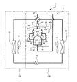
図2は、本実施の形態に係る冷凍サイクル装置2の要部構成として、蒸発器から圧縮機10、30を経て凝縮器までの冷媒回路を示す冷媒回路図である。図2では、圧縮機10、30については縦断面図で示しており、圧縮機10、30以外の構成要素についてはシンボル又はブロックで示している。また図2では、四方弁40の図示を省略している。図2中の「蒸発器」は、冷房運転の場合には室内熱交換器70であり、暖房運転の場合には室外熱交換器50である。また、図2中の「凝縮器」は、冷房運転の場合には室外熱交換器50であり、暖房運転の場合には室内熱交換器70である。
FIG. 2 is a refrigerant circuit diagram showing a refrigerant circuit from the evaporator through the
図2及び既に示した図1に示すように、2台の圧縮機10、30は冷媒回路に並列に接続されている。冷媒回路において四方弁40よりも下流側の吸入側配管は、分岐部43で圧縮機10、30の台数と同数(本例では2つ)の吸入側分岐配管41、42に分岐している。吸入側分岐配管41は圧縮機10の吸入側に接続されており、吸入側分岐配管42は圧縮機30の吸入側に接続されている。
As shown in FIG. 2 and FIG. 1 already shown, the two
また、圧縮機10の吐出側には吐出側分岐配管44が接続されており、圧縮機30の吐出側には吐出側分岐配管45が接続されている。吐出側分岐配管44、45には、それぞれ圧縮機10、30側への冷媒の逆流を阻止する逆止弁44a、45aが設けられている。吐出側分岐配管44と吐出側分岐配管45とは、四方弁40よりも上流側の合流部46で合流している。合流部46と四方弁40との間には、油分離器47が設けられている。油分離器47で回収された冷凍機油は、油戻り管48を通り、キャピラリチューブ48aで減圧されて圧縮機10、30の吸入側(本例では、四方弁40よりも下流側で分岐部43よりも上流側)に戻される。
Further, a discharge
圧縮機10の吐出側分岐配管44と吸入側分岐配管41との間は、圧縮機10起動時に吐出側と吸入側とを均圧化するためのバイパス配管52によって接続されている。バイパス配管52にはバルブ52aが設けられている。バルブ52aは、不図示の制御装置の制御により、圧縮機10の起動直前又は起動時に開状態となり、圧縮機10の起動から所定時間経過後に閉状態となる。同様に、圧縮機30の吐出側分岐配管45と吸入側分岐配管42との間はバイパス配管53によって接続されており、バイパス配管53にはバルブ53aが設けられている。バルブ53aは、圧縮機30の起動直前又は起動時に開状態となり、圧縮機30の起動から所定時間経過後に閉状態となる。
The discharge
次に、圧縮機10の構成について簡単に説明する。本実施の形態の圧縮機10は、2つのシリンダを備えた2シリンダロータリー圧縮機である。圧縮機10は、圧縮機構部11と、圧縮機構部11を駆動する電動機部12と、圧縮機構部11及び電動機部12を収容する密閉容器13と、を有している。本実施の形態の圧縮機10は、密閉容器13内の空間が吐出ガスで満たされる高圧容器タイプである。
Next, the configuration of the
電動機部12は、固定子14と回転子15とを有している。固定子14は、密閉容器13に対して固定されている。回転子15には、クランク軸16が嵌入されている。クランク軸16は、固定子14に電力が供給されることにより回転子15と共に回転駆動される。固定子14に電力を供給する電源として、本例では、冷媒循環量を可変とするためにクランク軸16の駆動回転数(周波数)を変化させることができるインバータ電源が用いられている。なお、固定子14に電力を供給する電源としては、周波数50Hz又は60Hzの一般商用電源を用いることもできる。クランク軸16には、互いに反対向きに、つまり180度位相をずらせて偏心した上下2つの偏心部(上偏心部16a、下偏心部16b)が形成されている。
The electric motor unit 12 includes a
圧縮機構部11は、電動機部12よりも下方に配置されている。圧縮機構部11は、上シリンダ17と、下シリンダ18と、上シリンダ17と下シリンダ18との間を仕切る仕切り板19と、上シリンダ17、下シリンダ18及び仕切り板19を積み重ねたものの上下両端に配置され、側壁を兼ねた主軸受20及び副軸受21と、上偏心部16aに嵌入された上ローリングピストン22と、下偏心部16bに嵌入された下ローリングピストン23と、上シリンダ17の内側を圧縮室と吸入室に仕切る上ベーン(図示せず)と、下シリンダ18の内側を圧縮室と吸入室に仕切る下ベーン(図示せず)と、を有している。
The
密閉容器13の側壁には、接続口13aが開口して形成されている。接続口13aには、後述する均油管55を接続するための接続管24が取り付けられている。すなわち、接続口13aには、接続管24を介して均油管55が接続される。接続口13aは、圧縮機構部11の摺動部(例えば、圧縮機構部11の全ての摺動部)よりも上方(本例では、上シリンダ17の上端面よりも上方)に設けられている。接続管24は、密閉容器13から水平に引き出された後に上向きに曲げられ、そのまま上方向に延伸した形状を有している。本例では、接続管24の先端24aは、密閉容器13の天井部の高さに近い高さに位置している。
A
密閉容器13の底部には、冷凍機油(潤滑油)が貯留されている。図2では、圧縮機10、30における冷凍機油の油面レベルOLがいずれも、概ね上シリンダ17の下端部よりも上方でかつ接続口13aよりも下方の位置にある良好な状態を示している。仮に、油面レベルOLが上シリンダ17の下端部よりも下方に位置していると、上シリンダ17内の摺動部で冷凍機油の不足が生じ得る。
Refrigerating machine oil (lubricating oil) is stored at the bottom of the sealed
圧縮機10の吸入側には、吸入した低圧冷媒を気液分離する吸入アキュムレータ25が設けられている。圧縮機10には、吸入アキュムレータ25内のガス冷媒のみが吸入されるようになっている。
On the suction side of the
圧縮機30については、上記の圧縮機10と実質的に同一の構成を有するため説明を省略する。本例の圧縮機10、30は、不図示の制御装置により、運転、停止、及び運転中の周波数(回転数)が互いに独立して制御されるようになっている。
Since the
圧縮機10に設けられた接続管24の先端24aと、圧縮機30に設けられた接続管24の先端24aとの間は、全体として逆U字状の形状を有する均油管55によって接続されている。これにより、圧縮機10、30同士は均油管55によって直接接続された構成となっている。ここで、「直接」とは、油分離器やオイルタンク等を間に介さないことを意味する。均油管55によって圧縮機10、30同士が接続されることにより、圧縮機10、30の内部空間同士が連通する。したがって、均油管55を介して圧縮機10、30間の一方から他方に冷凍機油を流通させることができるため、冷凍機油の偏在を即座に解消することが可能となる。また、均油管55を介して圧縮機10、30の内部圧を均圧化することができるため、圧縮機10、30の微小な運転状態の差による冷凍機油の偏在を予防することも可能となる。
The
均油管55にはバルブ(開閉弁)55aが設けられている。バルブ55aは、不図示の制御装置の制御により、均油管55を開閉するようになっている。本実施の形態では、圧縮機10、30がいずれも停止しているとき、又は圧縮機10、30が互いに実質的に同一の周波数(以下、単に「同一の周波数」という)で運転しているときには、バルブ55aが開状態となり、均油管55内の冷凍機油及び冷媒等の流通が許容される。また、圧縮機10、30の一方のみが運転しているとき、又は圧縮機10、30が互いに異なる周波数で運転しているときには、バルブ55aが閉状態となり、均油管55内の冷凍機油及び冷媒等の流通が阻止される。これにより、圧縮機10、30の一方のみが運転しているとき、又は圧縮機10、30が互いに異なる周波数で運転しているときには、バルブ55aは、逆止弁44a、45aと共に、圧縮機10、30の一方で圧縮された冷媒が他方に流入することを防ぐ機能を有している。したがって、言い換えれば、バルブ55a及び逆止弁44a、45aが設けられていることによって、圧縮機10、30の一方のみの運転、及び圧縮機10、30の互いに異なる周波数での運転が可能となる。
The
次に、本実施の形態に係る冷凍サイクル装置2の特徴的な動作について説明する。まず、圧縮機10、30の双方が互いに同一の周波数で運転しているときの動作について説明する。圧縮機10、30が互いに同一の周波数で運転しているときには、上述のように、均油管55に設けられたバルブ55aが開状態となる。これにより、圧縮機10の内部空間と圧縮機30の内部空間とが均油管55を介して連通する。このため、圧縮機10、30のうちの一方が油量過多となり他方が油量過少となった場合に、一方の圧縮機の余剰の冷凍機油を他方の圧縮機に均油管55を介して供給することができる。ここで、均油管55を介して供給される冷凍機油には、液体状態の冷凍機油だけでなく、ミスト状の冷凍機油も含まれる。したがって、一方の圧縮機の余剰の冷凍機油を他方の圧縮機に供給することができるのは、一方の圧縮機における冷凍機油の油面が接続口13aの位置にまで到達した場合のみに限られない。これにより、圧縮機10、30における冷凍機油の偏在を即座に解消することができる。また、圧縮機10の内部空間と圧縮機30の内部空間とが均油管55を介して連通することにより、両内部空間が均圧化する。このため、圧縮機10、30間での微小な運転状態の差による冷凍機油の偏在を予防することができる。
Next, a characteristic operation of the
次に、圧縮機10、30がいずれも停止しているときの動作について説明する。圧縮機10、30がいずれも停止しているときには、上述のように、均油管55に設けられたバルブ55aが開状態となる。これにより、圧縮機10の内部空間と圧縮機30の内部空間とが均油管55を介して連通する。このため、圧縮機10、30のうちの一方が油量過多となり他方が油量過少となっている場合には、一方の圧縮機の余剰の冷凍機油を他方の圧縮機に均油管55を介して供給することができる。
Next, the operation when both the
次に、圧縮機10、30の一方のみが運転しているとき(片側運転のとき。以下、3台以上の圧縮機のうち一部のみが運転している状態も片側運転という場合がある)の動作について説明する。ここでは、圧縮機10のみが運転しており圧縮機30が停止しているものとする。片側運転のときには、圧縮機10、30の内部空間の圧力に差が生じるため、上述のように、均油管55に設けられたバルブ55aが閉状態となる。運転している圧縮機10からは冷凍機油が圧縮冷媒と共に吐出され、冷凍機油の一部は油分離器47、油戻り管48及び吸入アキュムレータ25を介して圧縮機10内に返油される。これに対し、停止している圧縮機30からは冷凍機油が吐出されることはなく、運転中の圧縮機10から吐出された冷凍機油の一部が油分離器47、油戻り管48及び吸入アキュムレータ25を介して返油されるのみである。なお、圧縮機30側の吐出側分岐配管45には逆止弁45aが設けられているため、運転中の圧縮機10から停止中の圧縮機30への冷媒及び冷凍機油の逆流は防止される。
Next, when only one of the
これにより、片側運転のときには、運転中の圧縮機10では冷凍機油が徐々に減少し、停止中の圧縮機30では冷凍機油が徐々に増加することになる。しかしながら、片側運転が終了したとき(圧縮機10、30の双方が停止したとき)には、上述のように、均油管55に設けられたバルブ55aが開状態となる。このため、片側運転が終了したときに、圧縮機30が油量過多となり圧縮機10が油量過少となっている場合には、圧縮機10、30の停止中に、圧縮機30の余剰の冷凍機油を圧縮機10に均油管55を介して供給することができる。したがって、圧縮機10又は圧縮機30が次に起動するまでには、圧縮機10、30の双方で必要な油面レベルを確保することができる。これにより、圧縮機10、30の次回起動時の冷凍機油不足による不具合を防ぐことができるため、圧縮機10、30の次回起動時の信頼性を高めることができるとともに、圧縮機10、30の耐久性を向上することができる。このように、片側運転の終了時に圧縮機10、30の一方が油量過多となり他方が油量過少となっている場合に、本実施の形態による特に顕著な効果が得られる。
As a result, during one-side operation, the refrigeration oil gradually decreases in the
次に、圧縮機10、30が互いに異なる周波数で運転しているときの動作について説明する。ここでは、圧縮機10が相対的に高周波数で運転しており、圧縮機30が相対的に低周波数で運転しているものとする。圧縮機10、30が互いに異なる周波数で運転しているときには、圧縮機10、30の内部空間の圧力に差が生じるため、上述のように、均油管55に設けられたバルブ55aが閉状態となる。このとき、高周波数で運転している圧縮機10の冷凍機油は徐々に減少し、低周波数で運転している圧縮機30の冷凍機油は徐々に増加する、という現象が生じる。しかしながら、圧縮機10、30の運転が終了したときには、上述のように、均油管55に設けられたバルブ55aが開状態となる。このため、圧縮機10、30の運転が終了したときに、圧縮機30が油量過多となり圧縮機10が油量過少となっている場合には、圧縮機10、30の停止中に、圧縮機30の余剰の冷凍機油を圧縮機10に均油管55を介して供給することができる。したがって、圧縮機10又は圧縮機30が次に起動するまでには、圧縮機10、30の双方で必要な油面レベルを確保することができる。これにより、圧縮機10、30の次回起動時の冷凍機油不足による不具合を防ぐことができるため、圧縮機10、30の次回起動時の信頼性を高めることができるとともに、圧縮機10、30の耐久性を向上することができる。
Next, the operation when the
また、上記のように片側運転を行う際の信頼性が高まることで、空気条件による動作点別に圧縮機効率が最大となる箇所で使用できるよう、全数運転か運転台数を絞っての運転かを選択することができる。すなわち、全体としての冷凍能力は同一であっても、複数台の圧縮機の周波数を変更することにより運転台数を異ならせることができる。例えば、圧縮機が2台の場合、空気条件に応じて1台の圧縮機のみを60rpsで運転するか、又は2台の圧縮機のそれぞれを30rpsで運転するかで、圧縮機効率の良い方を選択することが可能となる。したがって、従来よりも省エネルギー効果の高い冷凍サイクル装置及び空気調和機を得ることができる。 In addition, as described above, the reliability when performing one-side operation increases, so that it can be used in places where the compressor efficiency is maximized for each operating point depending on the air condition, whether it is total operation or operation with a reduced number of operation. You can choose. That is, even if the refrigeration capacity as a whole is the same, the number of operating units can be made different by changing the frequency of a plurality of compressors. For example, when there are two compressors, only one compressor is operated at 60 rps depending on the air condition, or each of the two compressors is operated at 30 rps. Can be selected. Therefore, it is possible to obtain a refrigeration cycle apparatus and an air conditioner that have a higher energy saving effect than before.
図3は、本実施の形態に係る冷凍サイクル装置2の比較例として、均油管55及びバルブ55aを備えない冷凍サイクル装置の要部構成を示す冷媒回路図である。図3に示すように、この冷凍サイクル装置では、吐出側分岐配管44のうち逆止弁44aよりも上流側と、圧縮機10に設けられた接続管24の先端24aとの間が、油戻り管56によって接続されている。また、吐出側分岐配管45のうち逆止弁45aよりも上流側と、圧縮機30に設けられた接続管24の先端24aとの間が、油戻り管57によって接続されている。この構成では、圧縮機10、30から吐出側分岐配管44、45に冷媒と共に吐出された冷凍機油の一部は、油戻り管56、57を通って圧縮機10、30に戻るようになっている。
FIG. 3 is a refrigerant circuit diagram illustrating a main configuration of a refrigeration cycle apparatus that does not include the
図3に示す構成では、例えば圧縮機30のみが運転する片側運転の際、運転中の圧縮機30では冷凍機油が徐々に減少し、停止中の圧縮機10では冷凍機油が徐々に増加することになる。このとき、圧縮機30が油量過多となり圧縮機10が油量過少となった場合、本実施の形態とは異なり、片側運転が終了した後(圧縮機10、30が停止した後)にもその状態が維持される。ここで、図3では、圧縮機30の油面レベルOLが下シリンダ18の高さにあり、上シリンダ17で冷凍機油の不足が生じ得る状態を示している。このため、油量過少となった圧縮機30を次に起動するときに、冷凍機油の不足による不具合が生じるおそれがある。
In the configuration shown in FIG. 3, for example, in the one-side operation in which only the
次に、本実施の形態に係る冷凍サイクル装置2及び空気調和機1の全体的な冷房運転動作について簡単に説明する。圧縮機10、30によって圧縮され吐出された高温高圧のガス冷媒は、四方弁40を経由して、室外熱交換器50に流入する。室外熱交換器50に流入したガス冷媒は、室外機用ファン51により送風される外気との熱交換により凝縮し、低温の冷媒となって、室外熱交換器50から流出する。室外熱交換器50から流出した冷媒は、膨張装置60によって膨張及び減圧され、低温低圧の気液二相冷媒となる。この気液二相冷媒は、室内機200の室内熱交換器70に流入し、室内機用ファン71により送風される室内空気との熱交換により蒸発し、低温低圧のガス冷媒となって室内熱交換器70から流出する。このとき、冷媒に吸熱されて冷却された室内空気は、空調空気(冷風)となって、室内機200の吹出口から室内(空調対象空間)に吹き出される。室内熱交換器70から流出したガス冷媒は、四方弁40を経由して圧縮機10、30に吸入され、再び圧縮される。以上の動作が繰り返される。以上の動作において、冷媒回路内には、冷媒ガスだけでなくミスト状の冷凍機油も循環する。
Next, the overall cooling operation of the
次に、冷凍サイクル装置2及び空気調和機1の暖房運転動作について説明する。圧縮機10、30によって圧縮され吐出された高温高圧のガス冷媒は、四方弁40を経由して、室内機200の室内熱交換器70に流入する。室内熱交換器70に流入したガス冷媒は、室内機用ファン71により送風される室内空気との熱交換により凝縮し、低温の冷媒となって、室内熱交換器70から流出する。このとき、冷媒から吸熱して加熱された室内空気は、空調空気(温風)となって、室内機200の吹出口から室内に吹き出される。室内熱交換器70から流出した冷媒は、膨張装置60によって膨張及び減圧され、低温低圧の気液二相冷媒となる。この気液二相冷媒は、室外熱交換器50に流入し、室外機用ファン51により送風される外気との熱交換により蒸発し、低温低圧のガス冷媒となって室外熱交換器50から流出する。室外熱交換器50から流出したガス冷媒は、四方弁40を経由して圧縮機10、30に吸入され、再び圧縮される。以上の動作が繰り返される。以上の動作において、冷媒回路内には、冷媒ガスだけでなくミスト状の冷凍機油も循環する。
Next, the heating operation operation of the
以上説明したように、本実施の形態では、圧縮機10、30同士を接続して圧縮機10、30の内部空間を連通させ、圧縮機10、30間の一方から他方に冷凍機油を流通させる均油管55が設けられている。この構成によれば、油量過多となった圧縮機10、30の一方から油量過少となった圧縮機10、30の他方に、均油管55を介して余剰の冷凍機油(液体状態又はミスト状)を供給することができる(均油効果)。したがって、圧縮機10、30内の保持油量の偏在を即座に解消することができる。また、この構成によれば、均油管55を介して圧縮機10、30のそれぞれの内部空間を均圧化することができる(均圧効果)。したがって、圧縮機10、30間での微小な運転状態の差による冷凍機油の偏在を予防することができる。
As described above, in the present embodiment, the
また本実施の形態では、均油管55を開閉するバルブ55aが設けられている。この構成によれば、一方の圧縮機の油面レベルが低下した際に、他方の圧縮機の油面レベルも下部まで低下してしまうことを回避することができる。したがって、各圧縮機10、30で必要な油面レベルを確保することができる。
In the present embodiment, a
また本実施の形態では、圧縮機10、30の密閉容器13の側壁に、均油管55に接続される接続口13aが形成されており、接続口13aは、圧縮機10、30の圧縮機構部11よりも上方に設けられている。この構成によれば、一方の圧縮機の油面レベルが低下した際に、他方の圧縮機の油面レベルも下部まで低下してしまうことを回避することができる。したがって、必要な油面レベルを圧縮機10、30の両方で確保できなくなることを回避することができる。
Moreover, in this Embodiment, the
また本実施の形態では、バルブ55aは、圧縮機10、30がいずれも停止しているとき、又は圧縮機10、30が互いに同一の周波数で運転しているときには開状態となり、圧縮機10、30の一部(本例では、圧縮機10、30の一方)のみが運転しているとき、又は圧縮機10、30が互いに異なる周波数で運転しているときには閉状態となる。この構成によれば、圧縮機10、30の運転が終了したときに、圧縮機30が油量過多となり圧縮機10が油量過少となっている場合には、圧縮機10、30の停止中に、圧縮機30の余剰の冷凍機油を圧縮機10に均油管55を介して供給することができる。したがって、圧縮機10又は圧縮機30が次に起動するまでには、圧縮機10、30の双方で必要な油面レベルを確保することができるため、圧縮機10、30の次回起動時の信頼性を高めることができる。
Further, in the present embodiment, the
その他の実施の形態.
本発明は、上記実施の形態に限らず種々の変形が可能である。
例えば、上記実施の形態では2台の圧縮機が並列に接続された冷凍サイクル装置を例に挙げたが、本発明は、3台以上の圧縮機が並列に接続された冷凍サイクル装置にも適用できる。図4は、上記実施の形態の変形例として、3台以上の圧縮機を備える冷凍サイクル装置における均油管の接続構造の例を示す概略の上面図である。
Other embodiments.
The present invention is not limited to the above embodiment, and various modifications can be made.
For example, in the above-described embodiment, a refrigeration cycle apparatus in which two compressors are connected in parallel has been described as an example. However, the present invention is also applicable to a refrigeration cycle apparatus in which three or more compressors are connected in parallel. it can. FIG. 4 is a schematic top view illustrating an example of a connection structure of oil equalizing pipes in a refrigeration cycle apparatus including three or more compressors as a modification of the above embodiment.
図4(a)に示す例では、冷媒回路に並列に接続された3台の圧縮機301〜303が設けられている。圧縮機301〜303のそれぞれは、先端が2つに分岐した接続管301a〜303aを有している。接続管301aの一方の先端と、接続管302aの一方の先端との間は、均油管311を介して接続されている。接続管302aの他方の先端と、接続管303aの一方の先端との間は、均油管312を介して接続されている。接続管303aの他方の先端と、接続管301aの他方の先端との間は、均油管313を介して接続されている。均油管311〜313のそれぞれには、バルブ311a〜313aが設けられている。すなわち、図4(a)に示す例では、3台の圧縮機301〜303のそれぞれは、バルブ311a〜313aが設けられた均油管311〜313を介して、他の2台の圧縮機に1対1で接続されている。 In the example shown to Fig.4 (a), the three compressors 301-303 connected in parallel with the refrigerant circuit are provided. Each of the compressors 301 to 303 has connecting pipes 301a to 303a whose tip is branched into two. One end of the connecting pipe 301a and one end of the connecting pipe 302a are connected via an oil equalizing pipe 311. The other end of the connection pipe 302a and one end of the connection pipe 303a are connected via an oil equalizing pipe 312. The other end of the connecting pipe 303a and the other end of the connecting pipe 301a are connected via an oil equalizing pipe 313. Valves 311a to 313a are provided in the oil equalizing tubes 311 to 313, respectively. That is, in the example shown in FIG. 4A, each of the three compressors 301 to 303 is connected to the other two compressors via oil leveling tubes 311 to 313 provided with valves 311a to 313a. Connected in a one-to-one relationship.
図4(a)に示す例におけるバルブ311a〜313aの開閉状態の例について説明する。圧縮機301〜303の全てが同一の周波数で運転しているとき、又は圧縮機301〜303の全てが停止しているときには、全てのバルブ311a〜313aが開状態となる。圧縮機301、302が同一の周波数で運転し、圧縮機303が停止しているとき(又は圧縮機303のみが異なる周波数で運転しているとき)には、圧縮機301、302間のバルブ311aのみが開状態となり、それ以外のバルブ312a、313aが閉状態となる。圧縮機301のみが運転し、圧縮機302、303が停止しているときには、全てのバルブ311a〜313aが閉状態となる。圧縮機301、302が互いに異なる周波数で運転し、圧縮機303が停止しているとき、又は圧縮機301〜303の全てが異なる周波数で運転しているときには、全てのバルブ311a〜313aが閉状態となる。図4(a)に示す構成によれば、上記のようにバルブ311a〜313aを動作させることにより、上記実施の形態と同様の効果が得られる。 An example of the open / close state of the valves 311a to 313a in the example shown in FIG. When all of the compressors 301 to 303 are operating at the same frequency, or when all of the compressors 301 to 303 are stopped, all the valves 311a to 313a are opened. When the compressors 301 and 302 are operating at the same frequency and the compressor 303 is stopped (or when only the compressor 303 is operating at a different frequency), a valve 311a between the compressors 301 and 302 is used. Only the valve 312a and 313a are closed. When only the compressor 301 is operating and the compressors 302 and 303 are stopped, all the valves 311a to 313a are closed. When the compressors 301 and 302 operate at different frequencies and the compressor 303 is stopped, or when all of the compressors 301 to 303 operate at different frequencies, all the valves 311a to 313a are closed. It becomes. According to the configuration shown in FIG. 4A, the same effects as in the above embodiment can be obtained by operating the valves 311a to 313a as described above.
図4(b)に示す例では、冷媒回路に並列に接続された4台の圧縮機301〜304が設けられている。この例で用いられる均油管320は、中心部325と、中心部325から放射状に分岐した、圧縮機301〜304の台数に等しい数の放射状部321〜324と、を有している。放射状部321〜324のそれぞれの先端は、圧縮機301〜304(接続管)に接続されている。放射状部321〜324のそれぞれには、バルブ321a〜324aが設けられている。すなわち、図4(b)に示す例では、圧縮機301〜304のそれぞれは、バルブ321a〜324aが設けられた放射状部321〜324を介して、中心部325に接続されている。 In the example shown in FIG. 4B, four compressors 301 to 304 connected in parallel to the refrigerant circuit are provided. The oil equalizing pipe 320 used in this example has a central portion 325 and radial portions 321 to 324 having a number equal to the number of the compressors 301 to 304 that are radially branched from the central portion 325. The distal ends of the radial parts 321 to 324 are connected to the compressors 301 to 304 (connection pipes). Valves 321a to 324a are provided in the radial portions 321 to 324, respectively. That is, in the example shown in FIG. 4B, each of the compressors 301 to 304 is connected to the center portion 325 via radial portions 321 to 324 provided with valves 321a to 324a.
図4(b)に示す例におけるバルブ321a〜324aの開閉状態の例について説明する。4台の圧縮機301〜304の全てが同一の周波数で運転しているとき、又は4台の圧縮機301〜304の全てが停止しているときには、全てのバルブ321a〜324aが開状態となる。3台の圧縮機301、302、303が同一の周波数で運転し、1台の圧縮機304が停止しているとき(又は1台の圧縮機304のみが異なる周波数で運転しているとき)には、バルブ321a〜323aが開状態となり、バルブ324aのみが閉状態となる。1台の圧縮機301のみが運転し、3台の圧縮機302、303、304が停止しているときには、全てのバルブ321a〜324aが閉状態となる。2台の圧縮機301、302が同一の周波数で運転し、1台の圧縮機303が異なる周波数で運転し、1台の圧縮機304が停止しているときには、バルブ321a、322aが開状態となり、バルブ323a、324aが閉状態となる。2台の圧縮機301、302が同一の周波数で運転し、2台の圧縮機303、304が圧縮機301、302とは異なる同一の周波数で運転しているときには、バルブ321a、322aが開状態となりバルブ323a、324aが閉状態となるか、又はバルブ321a、322aが閉状態となりバルブ323a、324aが開状態となる。 An example of the open / closed state of the valves 321a to 324a in the example shown in FIG. 4B will be described. When all of the four compressors 301 to 304 are operating at the same frequency, or when all of the four compressors 301 to 304 are stopped, all the valves 321a to 324a are opened. . When three compressors 301, 302, and 303 are operating at the same frequency and one compressor 304 is stopped (or when only one compressor 304 is operating at a different frequency) The valves 321a to 323a are opened, and only the valve 324a is closed. When only one compressor 301 is operating and the three compressors 302, 303, 304 are stopped, all the valves 321a to 324a are closed. When two compressors 301 and 302 operate at the same frequency, one compressor 303 operates at a different frequency, and one compressor 304 is stopped, the valves 321a and 322a are opened. The valves 323a and 324a are closed. When the two compressors 301 and 302 operate at the same frequency and the two compressors 303 and 304 operate at the same frequency different from the compressors 301 and 302, the valves 321a and 322a are in the open state. Then, the valves 323a and 324a are closed, or the valves 321a and 322a are closed and the valves 323a and 324a are opened.
図4(b)に示す構成によれば、上記のようにバルブ321a〜324aを動作させることにより、上記実施の形態と同様の効果が得られる。また、図4(a)に示した構成と比較すると、図4(b)に示す構成では、圧縮機301〜304の台数が多いとき(4台以上のとき)のバルブ321a〜324aの数を削減することができる。 According to the configuration shown in FIG. 4B, the same effect as in the above embodiment can be obtained by operating the valves 321a to 324a as described above. Also, compared with the configuration shown in FIG. 4A, in the configuration shown in FIG. 4B, the number of valves 321a to 324a when the number of compressors 301 to 304 is large (when 4 or more) is used. Can be reduced.
図4(c)に示す例では、冷媒回路に並列に接続された4台の圧縮機301〜304が設けられている。この例で用いられる均油管330は、中心に環状に設けられた環状部335と、環状部335からそれぞれ放射状に分岐した、圧縮機301〜304の台数に等しい数の放射状部331〜334と、を有している。放射状部331〜334のそれぞれの先端は、圧縮機301〜304(接続管)に接続されている。放射状部331〜334のそれぞれには、バルブ331a〜334aが設けられている。すなわち、図4(c)に示す例では、圧縮機301〜304のそれぞれは、バルブ331a〜334aが設けられた放射状部331〜334を介して、環状部335に接続されている。 In the example shown in FIG. 4C, four compressors 301 to 304 connected in parallel to the refrigerant circuit are provided. The oil equalizing pipe 330 used in this example includes an annular portion 335 provided in an annular shape at the center, and radial portions 331 to 334 having a number equal to the number of the compressors 301 to 304 that are radially branched from the annular portion 335, respectively. have. The distal ends of the radial parts 331 to 334 are connected to the compressors 301 to 304 (connection pipes). Each of the radial parts 331 to 334 is provided with valves 331a to 334a. That is, in the example shown in FIG. 4C, each of the compressors 301 to 304 is connected to the annular portion 335 via radial portions 331 to 334 provided with valves 331a to 334a.
図4(c)に示す構成によれば、図4(b)に示したバルブ321a〜324aと同様にバルブ331a〜334aを動作させることにより、上記実施の形態と同様の効果が得られる。また、図4(c)に示す構成では、図4(b)に示した構成と比較すると、圧縮機301〜304の台数が多いときの均油管330の分岐構造を簡素化することができる。 According to the configuration shown in FIG. 4C, the same effects as in the above embodiment can be obtained by operating the valves 331a to 334a in the same manner as the valves 321a to 324a shown in FIG. Further, in the configuration shown in FIG. 4C, the branch structure of the oil equalizing pipe 330 when the number of the compressors 301 to 304 is large can be simplified as compared with the configuration shown in FIG.
また、上記実施の形態では2シリンダロータリー圧縮機を例に挙げたが、本発明は、1つ又は3つ以上のシリンダを備えたロータリー圧縮機にも適用できる。また、本発明は、ロータリー圧縮機以外の圧縮機にも適用できる。 In the above embodiment, a two-cylinder rotary compressor is taken as an example. However, the present invention can also be applied to a rotary compressor including one or three or more cylinders. The present invention can also be applied to a compressor other than the rotary compressor.
また上記の各実施の形態や変形例は、互いに組み合わせて実施することが可能である。 Further, the above embodiments and modifications can be implemented in combination with each other.
1 空気調和機、2 冷凍サイクル装置、10、30、301、302、303、304 圧縮機、11 圧縮機構部、12 電動機部、13 密閉容器、13a 接続口、14 固定子、15 回転子、16 クランク軸、16a 上偏心部、16b 下偏心部、17 上シリンダ、18 下シリンダ、19 仕切り板、20 主軸受、21 副軸受、22 上ローリングピストン、23 下ローリングピストン、24、301a、302a、303a 接続管、24a 先端、25 吸入アキュムレータ、40 四方弁、41、42 吸入側分岐配管、43 分岐部、44、45 吐出側分岐配管、44a、45a 逆止弁、46 合流部、47 油分離器、48 油戻り管、48a キャピラリチューブ、50 室外熱交換器、51 室外機用ファン、52、53 バイパス配管、52a、53a バルブ、55、311、312、313、320、330 均油管、55a、311a、312a、313a、321a、322a、323a、324a、331a、332a、333a、334a バルブ、56、57 油戻り管、60 膨張装置、70 室内熱交換器、71 室内機用ファン、100 室外機、200 室内機、321、322、323、324、331、332、333、334 放射状部、325 中心部、335 環状部、OL 油面レベル。 DESCRIPTION OF SYMBOLS 1 Air conditioner, 2 Refrigeration cycle apparatus 10, 30, 301, 302, 303, 304 Compressor, 11 Compression mechanism part, 12 Electric motor part, 13 Airtight container, 13a Connection port, 14 Stator, 15 Rotor, 16 Crankshaft, 16a Upper eccentric part, 16b Lower eccentric part, 17 Upper cylinder, 18 Lower cylinder, 19 Partition plate, 20 Main bearing, 21 Sub bearing, 22 Upper rolling piston, 23 Lower rolling piston, 24, 301a, 302a, 303a Connection pipe, 24a tip, 25 Suction accumulator, 40 Four-way valve, 41, 42 Suction side branch pipe, 43 Branch part, 44, 45 Discharge side branch pipe, 44a, 45a Check valve, 46 Junction part, 47 Oil separator, 48 oil return pipe, 48a capillary tube, 50 outdoor heat exchanger, 51 outdoor unit fan, 52, 3 Bypass piping, 52a, 53a valve, 55, 311, 312, 313, 320, 330 Oil equalizing pipe, 55a, 311a, 312a, 313a, 321a, 322a, 323a, 324a, 331a, 332a, 333a, 334a Valve, 56, 57 oil return pipe, 60 expansion device, 70 indoor heat exchanger, 71 fan for indoor unit, 100 outdoor unit, 200 indoor unit, 321, 322, 323, 324, 331, 332, 333, 334 radial part, 325 center part 335 Annulus, OL Oil level.
Claims (4)
前記圧縮機同士を接続して前記圧縮機の内部空間を連通させ、前記圧縮機間で冷凍機油を流通させる均油管と、
前記均油管を開閉するバルブと、
を有することを特徴とする冷凍サイクル装置。 A refrigeration cycle apparatus including a plurality of compressors connected in parallel,
An oil equalizing pipe that connects the compressors to communicate the internal space of the compressors and distributes refrigeration oil between the compressors;
A valve for opening and closing the oil equalizing pipe;
A refrigeration cycle apparatus comprising:
前記接続口は、前記圧縮機の圧縮機構部よりも上方に設けられていること
を特徴とする請求項1に記載の冷凍サイクル装置。 A connection port connected to the oil equalizing pipe is formed on the side wall of the compressor,
The refrigeration cycle apparatus according to claim 1, wherein the connection port is provided above a compression mechanism portion of the compressor.
前記圧縮機の一部のみが運転しているとき、又は前記圧縮機が互いに異なる周波数で運転しているときには閉状態となること
を特徴とする請求項1又は請求項2に記載の冷凍サイクル装置。 The valves are open when all of the compressors are stopped or when the compressors are operating at the same frequency,
The refrigeration cycle apparatus according to claim 1 or 2, wherein only a part of the compressor is operating, or the compressor is operating at a frequency different from each other. .
を特徴とする空気調和機。 An air conditioner comprising the refrigeration cycle apparatus according to any one of claims 1 to 3.
Priority Applications (3)
| Application Number | Priority Date | Filing Date | Title |
|---|---|---|---|
| JP2013072909A JP2014196874A (en) | 2013-03-29 | 2013-03-29 | Refrigeration cycle device and air conditioner including the same |
| CN201420145201.6U CN203785327U (en) | 2013-03-29 | 2014-03-28 | Refrigeration circulation device and air conditioner with same |
| CN201410120860.9A CN104075494A (en) | 2013-03-29 | 2014-03-28 | Refrigeration circulation device and air conditioner with the refrigeration circulation device |
Applications Claiming Priority (1)
| Application Number | Priority Date | Filing Date | Title |
|---|---|---|---|
| JP2013072909A JP2014196874A (en) | 2013-03-29 | 2013-03-29 | Refrigeration cycle device and air conditioner including the same |
Publications (2)
| Publication Number | Publication Date |
|---|---|
| JP2014196874A true JP2014196874A (en) | 2014-10-16 |
| JP2014196874A5 JP2014196874A5 (en) | 2015-09-17 |
Family
ID=51321506
Family Applications (1)
| Application Number | Title | Priority Date | Filing Date |
|---|---|---|---|
| JP2013072909A Pending JP2014196874A (en) | 2013-03-29 | 2013-03-29 | Refrigeration cycle device and air conditioner including the same |
Country Status (2)
| Country | Link |
|---|---|
| JP (1) | JP2014196874A (en) |
| CN (2) | CN203785327U (en) |
Cited By (2)
| Publication number | Priority date | Publication date | Assignee | Title |
|---|---|---|---|---|
| WO2023195042A1 (en) * | 2022-04-04 | 2023-10-12 | 三菱電機株式会社 | Refrigeration cycle device |
| US11953246B2 (en) * | 2020-09-30 | 2024-04-09 | Daikin Industries, Ltd. | Compression apparatus |
Families Citing this family (4)
| Publication number | Priority date | Publication date | Assignee | Title |
|---|---|---|---|---|
| JP2014196874A (en) * | 2013-03-29 | 2014-10-16 | 三菱電機株式会社 | Refrigeration cycle device and air conditioner including the same |
| CN104633998B (en) * | 2015-02-12 | 2017-10-31 | 三菱电机(广州)压缩机有限公司 | Rotor-type compressor parallel system |
| CN105135768A (en) * | 2015-09-30 | 2015-12-09 | 海信容声(广东)冷柜有限公司 | Refrigeration equipment and control method thereof |
| KR101738458B1 (en) * | 2016-02-26 | 2017-06-08 | 엘지전자 주식회사 | High pressure compressor and refrigerating machine having the same |
Citations (8)
| Publication number | Priority date | Publication date | Assignee | Title |
|---|---|---|---|---|
| JPH02264168A (en) * | 1989-04-05 | 1990-10-26 | Hitachi Ltd | Freezing device |
| JPH0510612A (en) * | 1991-06-28 | 1993-01-19 | Toshiba Corp | Air conditioner |
| JPH05256532A (en) * | 1992-03-10 | 1993-10-05 | Toshiba Ave Corp | Air-conditioner |
| JP2000046418A (en) * | 1998-07-30 | 2000-02-18 | Matsushita Electric Ind Co Ltd | Inverter type air conditioner |
| JP2004205175A (en) * | 2002-12-26 | 2004-07-22 | Toshiba Kyaria Kk | Refrigerator |
| JP2004293822A (en) * | 2003-03-25 | 2004-10-21 | Toshiba Kyaria Kk | Refrigeration cycle device |
| WO2009141956A1 (en) * | 2008-05-23 | 2009-11-26 | パナソニック株式会社 | Fluid machine and refrigeration cycle device |
| JP2011141078A (en) * | 2010-01-07 | 2011-07-21 | Panasonic Corp | Refrigeration cycle apparatus |
Family Cites Families (4)
| Publication number | Priority date | Publication date | Assignee | Title |
|---|---|---|---|---|
| JPH0282057A (en) * | 1988-09-19 | 1990-03-22 | Matsushita Refrig Co Ltd | Heat pump type air conditioner |
| CN100487346C (en) * | 2004-07-08 | 2009-05-13 | 乐金电子(天津)电器有限公司 | Air conditioner |
| CN101303180A (en) * | 2008-06-13 | 2008-11-12 | 广东志高空调有限公司 | Multiple-compressor parallel wind cooling module air conditioner system |
| JP2014196874A (en) * | 2013-03-29 | 2014-10-16 | 三菱電機株式会社 | Refrigeration cycle device and air conditioner including the same |
-
2013
- 2013-03-29 JP JP2013072909A patent/JP2014196874A/en active Pending
-
2014
- 2014-03-28 CN CN201420145201.6U patent/CN203785327U/en not_active Expired - Fee Related
- 2014-03-28 CN CN201410120860.9A patent/CN104075494A/en active Pending
Patent Citations (8)
| Publication number | Priority date | Publication date | Assignee | Title |
|---|---|---|---|---|
| JPH02264168A (en) * | 1989-04-05 | 1990-10-26 | Hitachi Ltd | Freezing device |
| JPH0510612A (en) * | 1991-06-28 | 1993-01-19 | Toshiba Corp | Air conditioner |
| JPH05256532A (en) * | 1992-03-10 | 1993-10-05 | Toshiba Ave Corp | Air-conditioner |
| JP2000046418A (en) * | 1998-07-30 | 2000-02-18 | Matsushita Electric Ind Co Ltd | Inverter type air conditioner |
| JP2004205175A (en) * | 2002-12-26 | 2004-07-22 | Toshiba Kyaria Kk | Refrigerator |
| JP2004293822A (en) * | 2003-03-25 | 2004-10-21 | Toshiba Kyaria Kk | Refrigeration cycle device |
| WO2009141956A1 (en) * | 2008-05-23 | 2009-11-26 | パナソニック株式会社 | Fluid machine and refrigeration cycle device |
| JP2011141078A (en) * | 2010-01-07 | 2011-07-21 | Panasonic Corp | Refrigeration cycle apparatus |
Cited By (2)
| Publication number | Priority date | Publication date | Assignee | Title |
|---|---|---|---|---|
| US11953246B2 (en) * | 2020-09-30 | 2024-04-09 | Daikin Industries, Ltd. | Compression apparatus |
| WO2023195042A1 (en) * | 2022-04-04 | 2023-10-12 | 三菱電機株式会社 | Refrigeration cycle device |
Also Published As
| Publication number | Publication date |
|---|---|
| CN104075494A (en) | 2014-10-01 |
| CN203785327U (en) | 2014-08-20 |
Similar Documents
| Publication | Publication Date | Title |
|---|---|---|
| US10605492B2 (en) | Refrigeration cycle device | |
| JP5711448B2 (en) | Heat pump system | |
| JP2014196874A (en) | Refrigeration cycle device and air conditioner including the same | |
| WO2009147826A1 (en) | Refrigeration cycle device | |
| US9222706B2 (en) | Refrigeration cycle apparatus and operating method of same | |
| WO2007063798A1 (en) | Freezing apparatus | |
| KR20080083784A (en) | Compression system and air-conditioning system using the same | |
| JP2017150466A (en) | High pressure compressor and refrigeration cycle device having the same | |
| KR20070082501A (en) | Air-conditioning system and controlling method for the same | |
| JP6727420B2 (en) | Air conditioner | |
| JP2012145251A (en) | Heat pump device | |
| KR101275921B1 (en) | Hermetic type compressor | |
| JP2019020080A (en) | Air conditioning device and operation method therefor | |
| JP6395643B2 (en) | Air conditioner | |
| JP5971633B2 (en) | Refrigeration cycle equipment | |
| JP6242235B2 (en) | Heat source unit and refrigeration cycle apparatus | |
| JP2004143951A (en) | Scroll compressor | |
| JP5176897B2 (en) | Refrigeration equipment | |
| JP2007147228A (en) | Refrigerating device | |
| JP6749526B1 (en) | Outdoor unit and refrigeration cycle device | |
| JP2012247097A (en) | Refrigerating cycle apparatus | |
| JP2013139897A (en) | Refrigerating device | |
| JP2021071208A (en) | Refrigerating device | |
| JP2013139904A (en) | Refrigerating device | |
| JP5913402B2 (en) | Heat pump system |
Legal Events
| Date | Code | Title | Description |
|---|---|---|---|
| A521 | Request for written amendment filed |
Free format text: JAPANESE INTERMEDIATE CODE: A523 Effective date: 20150730 |
|
| A621 | Written request for application examination |
Free format text: JAPANESE INTERMEDIATE CODE: A621 Effective date: 20150730 |
|
| A977 | Report on retrieval |
Free format text: JAPANESE INTERMEDIATE CODE: A971007 Effective date: 20160525 |
|
| A131 | Notification of reasons for refusal |
Free format text: JAPANESE INTERMEDIATE CODE: A131 Effective date: 20160705 |
|
| A521 | Request for written amendment filed |
Free format text: JAPANESE INTERMEDIATE CODE: A523 Effective date: 20160822 |
|
| A131 | Notification of reasons for refusal |
Free format text: JAPANESE INTERMEDIATE CODE: A131 Effective date: 20161220 |
|
| A521 | Request for written amendment filed |
Free format text: JAPANESE INTERMEDIATE CODE: A523 Effective date: 20170206 |
|
| A02 | Decision of refusal |
Free format text: JAPANESE INTERMEDIATE CODE: A02 Effective date: 20170523 |