EP1443221B1 - Ventileinrichtung und hydraulisches System - Google Patents
Ventileinrichtung und hydraulisches System Download PDFInfo
- Publication number
- EP1443221B1 EP1443221B1 EP04001514A EP04001514A EP1443221B1 EP 1443221 B1 EP1443221 B1 EP 1443221B1 EP 04001514 A EP04001514 A EP 04001514A EP 04001514 A EP04001514 A EP 04001514A EP 1443221 B1 EP1443221 B1 EP 1443221B1
- Authority
- EP
- European Patent Office
- Prior art keywords
- inlet
- chamber
- outflow
- valve
- hydraulic system
- Prior art date
- Legal status (The legal status is an assumption and is not a legal conclusion. Google has not performed a legal analysis and makes no representation as to the accuracy of the status listed.)
- Expired - Lifetime
Links
- 238000004146 energy storage Methods 0.000 claims description 21
- 238000006073 displacement reaction Methods 0.000 claims description 11
- 230000008878 coupling Effects 0.000 claims description 6
- 238000010168 coupling process Methods 0.000 claims description 6
- 238000005859 coupling reaction Methods 0.000 claims description 6
- 239000012528 membrane Substances 0.000 claims 1
- 239000012530 fluid Substances 0.000 abstract description 5
- 238000000034 method Methods 0.000 description 12
- 230000008569 process Effects 0.000 description 8
- 238000011144 upstream manufacturing Methods 0.000 description 6
- 230000008901 benefit Effects 0.000 description 2
- 230000006835 compression Effects 0.000 description 2
- 238000007906 compression Methods 0.000 description 2
- 230000005283 ground state Effects 0.000 description 2
- 230000004048 modification Effects 0.000 description 2
- 238000012986 modification Methods 0.000 description 2
- 230000001105 regulatory effect Effects 0.000 description 2
- 230000007704 transition Effects 0.000 description 2
- 230000000712 assembly Effects 0.000 description 1
- 238000000429 assembly Methods 0.000 description 1
- 230000000903 blocking effect Effects 0.000 description 1
- 238000001816 cooling Methods 0.000 description 1
- 230000000694 effects Effects 0.000 description 1
- 230000006872 improvement Effects 0.000 description 1
- 230000007935 neutral effect Effects 0.000 description 1
- 230000035484 reaction time Effects 0.000 description 1
Images


Classifications
-
- F—MECHANICAL ENGINEERING; LIGHTING; HEATING; WEAPONS; BLASTING
- F15—FLUID-PRESSURE ACTUATORS; HYDRAULICS OR PNEUMATICS IN GENERAL
- F15B—SYSTEMS ACTING BY MEANS OF FLUIDS IN GENERAL; FLUID-PRESSURE ACTUATORS, e.g. SERVOMOTORS; DETAILS OF FLUID-PRESSURE SYSTEMS, NOT OTHERWISE PROVIDED FOR
- F15B21/00—Common features of fluid actuator systems; Fluid-pressure actuator systems or details thereof, not covered by any other group of this subclass
- F15B21/04—Special measures taken in connection with the properties of the fluid
- F15B21/041—Removal or measurement of solid or liquid contamination, e.g. filtering
-
- G—PHYSICS
- G05—CONTROLLING; REGULATING
- G05D—SYSTEMS FOR CONTROLLING OR REGULATING NON-ELECTRIC VARIABLES
- G05D16/00—Control of fluid pressure
- G05D16/04—Control of fluid pressure without auxiliary power
- G05D16/10—Control of fluid pressure without auxiliary power the sensing element being a piston or plunger
- G05D16/101—Control of fluid pressure without auxiliary power the sensing element being a piston or plunger the controller being arranged as a multiple-way valve
Definitions
- the invention relates to a hydraulic system with a valve device, in detail with the features of the preamble of claim 1.
- Valve devices in the form of pressure control valves for use in hydraulic circuits are well known.
- the function of such a pressure control valve is essentially to ensure a certain pressure or pressure curve in the system. In this case, the higher pressure causing excess amount of equipment is generally discharged.
- a major disadvantage of this design is that all functional elements in the flow direction in front of this valve, z. B. in the form of filters and heat exchangers, thereby flowed through with the entire amount of resources and not only the amount actually required to build up the pressure. This results in practice very high loads on the upstream functional elements. Furthermore, the pressure losses incurred by these elements are not negligible.
- Known solutions for reducing the amount by regulating the inflow, z. As a controllable pump, require a considerable additional effort and the reaction times of such a unit are simply too slow for many applications.
- the invention is therefore based on the object, a hydraulic system with a valve device, in particular a pressure control valve of the type mentioned in such a way that on the one hand the working pressure can be controlled with little effort and further the pressure losses are reduced by the inlet upstream functional elements. Furthermore, should These upstream functional elements are loaded less in continuous operation, so that no corresponding over-dimensioning must take place on the maximum inflow more.
- the valve device in particular a pressure control valve of the hydraulic system, comprises a valve housing and an axially displaceably mounted in this valve piston, which on one side with an energy storage device for generating a counter force to the force in the pressure chamber and definition of the opening pressures can be acted upon, this in the unloaded state in his Neutral position spends, and according to the invention means for realizing one or more Abströmfunktionen.
- This can be used in hydraulic systems for pressure regulation or limitation.
- the piston has areas of different diameters, wherein the control edge forming areas pressure and liquid-tight on the housing are feasible. These areas of different diameters form so-called chambers, a working chamber and a discharge chamber and a, limited by the valve piston and the valve housing and variable in size pressure chamber.
- the working chamber is arranged via a feed arranged in the housing, which can be coupled to the inflow line and a drain connected.
- the outflow chamber is according to the invention free of a connection to the working chamber and the inlet of the working chamber. In this case, the outflow inlet and the outflow are offset from each other either in the axial direction, that is arranged in two different axial planes or in a plane.
- the outflow inlet is viewed via a connecting line in the flow direction before the functional elements comprising a heat exchanger and / or a filter device, coupled to the supply line.
- the design of the valve piston in particular the Dimensioning of the individual regions of different diameter in the axial direction is dimensioned such that the valve piston releases the inlet to the outflow chamber until a predefined maximum pressure in the working chamber is reached, but blocks the outflow flow. Only when exceeding this pressure is a release of the connection between the outflow and the outflow.
- the outflow inlet is coupled to the inflow line, wherein the coupling takes place in the flow direction of the operating medium in front of the functional elements with the inflow line.
- the control of the position of the valve piston via the adjustable balance of forces of pressure chamber and energy storage device, which may be designed as a spring unit or further pressure chamber. As a result, the control of the release or blocking of inflow and outflow of the working space takes place.
- the solution according to the invention makes it possible with a valve piston, but completely separate, the working pressure in the system, d. H. to control the discharge line coupled to the working chamber by outflow of equipment in front of the upstream elements.
- This ensures that the upstream elements - heat exchanger or cooling device or filter - which are located between the two terminals of the valve device, in particular the pressure control valve, are only flowed through by the actually required amount of equipment of the system and thus the total load is less and none additional pressure losses are generated.
- the reduced or no power dissipation also has a considerable influence on the total power loss of the entire system.
- valve piston there are several possibilities. This depends in particular on the required connections to the consumer. A distinction is made between valve assemblies with a connection, ie a flow to the consumer and several processes.
- the working chamber can be in the axial direction next to the Be arranged discharge chamber, wherein the outflow chamber is then arranged in the axial direction, for example, between the working chamber and the energy storage unit. It is essential that the dimensioning of the individual piston areas in the axial direction takes place in such a way that, when a certain predefined working pressure is reached, a displacement of the piston effects a release of the outflow sequence.
- the arrangement of resource inlet and operating fluid outlet in the valve housing determines the valve piston shape, in particular the position of the control edges, considerably with.
- a pressure chamber is provided, which is provided only for acting on the piston for the purpose of displacement.
- a resource flow is diverted, which serves solely to act on the piston. The diversion can take place at an illuminated point of the inflow line.
- Decisive is the arrangement of the pressure chamber in the valve housing relative to the working chamber. In the process, between the pressure chamber, which is free of a drain and the energy storage device - force equilibrium, there is no more displacement on the piston. The functional position has been reached. However, if the pressure in the pressure chamber again larger, the piston moves in the axial direction against the biasing device, which is preferably designed in the form of a spring unit and causes a release between the inlet and a further flow and further displacement also the outflow and the outflow , The displacement of the piston is always carried out only in accordance with the balance of power between the pressure chamber and biasing device.
- the biasing device can be designed as a spring unit or else in the form of a further pressure chamber.
- the pressure chamber is simultaneously formed by the working space.
- only one drain is preferably provided.
- This and the inlet to the working chamber can be considered in the axial direction to each other, offset in two planes, when the piston can close the working chamber drain.
- the arrangement can also be done in a plane.
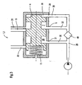
- FIG. 1 illustrates a schematic representation of a first embodiment of an inventively designed hydraulic system with a valve device 1, in particular in the form of a pressure control valve 2 based on a section of a hydraulic system.
- the valve device 1 comprises a valve housing 3 and a valve piston 4.
- the valve piston 4 is slidably mounted in the valve housing 3.
- the valve device 1 comprises at least one inlet 5 and at least one outlet 6, which can be coupled to a consumer.
- the connection between the inlet 5 and the drain 6 via a working chamber 7.
- the working chamber 7 is formed in the illustrated case by areas of different diameters 8.1 and 8.2 and 8.3 on the valve piston 4.
- the individual chambers are realized according to a preferred embodiment by the different dimensions of the piston in the radial direction.
- the areas 8.1 and 8.3 are designed in terms of their diameter such that the valve piston 4 is guided in these areas tight in the valve housing 3.
- the area 8.2 has a smaller diameter than the two adjacent areas 8.1 and 8.3.
- the thus formed control edges 9 and 10 and the outer periphery of the valve piston 4 in the area 8.2 describe the working chamber 7. According to the position of the valve piston 4 in the valve housing 3 with respect to the inlet 5 and the drain 6, the working chamber 7 of the connection between the inlet 5 and the process 6, which can be coupled to a consumer.
- the connections between the inlet 5 and the outlet 6 are arranged offset in the axial direction to each other in the illustrated case, so that the valve piston 4 assumes a position in the unloaded state, which blocks the connection between the inlet 5 and the drain 6, in detail
- the drain 6 is covered by the area 8.3, while the area 8.2 is above the inlet 5 and thus a connection between the inlet 5 and the working chamber 7 is given.
- the valve piston 4 is displaced against a spring device 11, which is arranged between the valve housing 3 and the valve piston 4 and in the unloaded state, ie when no supply of working fluid to the consumer conveys the valve piston due to the spring force in a position which blocks the drain 6.
- the spring device 11 is designed as a compression spring.
- a filter, heat exchanger or other functional element 40 are provided in the feed line 29 coupled to the inlet 5, which are acted upon by the total flow rate, the actual function as a pressure control valve or pressure relief valve only within the Valve device is realized by outflow of operating medium, the outflow takes place only after the inlet in the valve device.
- valve piston 4 the working pressure in the system, ie in the couplable with a consumer connection on the drain 6 by outflow of the medium in front of the upstream elements, such as z. B. filters and / or heat exchanger controls.
- the valve piston 4 has two further regions of different diameters, in this case 12.1 and 12.2, which adjoin the region of different diameter 8.3 in the illustrated case.
- the spring device 11 is arranged between the valve housing 3 and the end face 13 of the valve piston 4 facing the valve housing, which is formed by the end face 14 at the area of different diameter 12.1.
- the two areas of different diameters 12.1 and 12.2 also form control edges, a first control edge 15 which is formed by the end face 16 directed away from the spring device 11 on the region 12.1 and a second control edge 17 which extends from the end face 18 adjacent to the region 12.2 Area of different diameter 8.3 is formed.
- the control edges 15 and 17 and the outer periphery 19 in the region 12.2 form a discharge chamber 20.
- the control edges 15 and 17 serve to separate the space 20 of 7.
- the outflow edge 20 can be coupled with a valve housing 3 disposed outflow inlet 21 and a discharge 22. The coupling takes place here via the position of the valve piston 4.
- the arrangement of the regions of different diameter in the valve piston 4 and the function assignment to each other can also be done differently.
- the outflow inlet 21 is connected in the flow direction in front of the functional elements 40, ie the heat exchanger and / or filter, via a line section to the inflow line 29. Also here are outflow 21 and outflow 22 in the valve housing 3 viewed in the axial direction offset from each other.
- the valve piston 4 also has a further section smaller diameter than the valve housing 3, in particular the interior 23 of the valve housing 3, on. This section of smaller diameter is denoted by 24 and forms, directed away from the spring device 11 face 25 of the valve piston 4.
- this area of smaller diameter 24 with the adjacent area 8.1 and the interior 23 of the valve housing 3 describes another chamber, which also serves as a pressure chamber 26 is referred to, which is coupled to the Radioffenzulig, wherein the coupling is analogous to that of the working chamber 7 and the connection to the supply line 29 behind the functional elements 40 heat exchanger, filter, etc. is provided.
- this chamber is exclusively responsible for the regulation, ie desired piston movement.
- the area of smaller diameter 24 is only necessary if the inflow 28 comes from the side, since otherwise the control flow 28 would close forever if no pressure is applied. This means that the inflow 28 is always kept open.
- the smaller diameter portion 24 could be eliminated if the inlet 28 instead of as in FIG.
- valve piston 4 In the fully unloaded state, the valve piston 4 is acted upon solely by the force of the spring device 11 on its end face 13. This is located in a position in which the end face 25 rests against the end face 27, which delimits the interior space 23 in the axial direction, in the valve housing 3, as in FIG. 3 represented, or forms a gap with this.
- the individual areas of different cross section or diameter 8.1 to 8.3, 12.1, 12.2 and 24 are designed with respect to their axial extent such that in the unloaded state of the outflow 22 is blocked. However, the outflow inlet 21 and the inlet 5 are coupled to the outflow chamber 20 and the working chamber 7.
- second inlet 28 to the pressure chamber 26, which is coupled to the inflow line 29 behind the functional elements 40, heat exchanger and / or filter.
- a portion of the guided in the inflow line 29 operating fluid flows via the connecting line 30 to the outflow 21 and from there into the outflow 20. This happens as long as the outflow 21 is released.
- operating medium is conducted via the inflow line 29 into the working chamber 20 and the pressure chamber 26 via the inlet 5 and the inlet 28. In this case, a pressure builds up in the pressure chamber 26.
- a further second flow 31 may be provided, which couples the first working chamber 7 with another consumer.
- the second sequence 31 is arranged in the axial direction at a level with the inlet 5, which is why via the connecting line 32 with the inlet line 29 to the inlet 5 resources through the first working chamber 7 without displacement of the piston 4 already direct resources to the second outlet 31 and for consumers to be directed.
- the process 6 is still closed in this state.
- the drain 31 forms here a small throttled drain.
- a higher pressure is set.
- the drain 6 is open.
- Conceivable but not shown here, is the provision of several throttled and / or unthrottled outlets in any position, depending on the desired gradation of the working pressure control.
- the additional (throttled) outlets are also used to regulate the flow rate for a particular consumer, which is to receive its full amount upon opening the large outlet bore, but must be previously supplied to a reduced extent.
- the pressure chamber 26th supplied with operating means via a connecting line 33 between the second inlet 28 and the inflow line 29 in the flow direction behind the functional elements 40, heat exchangers and / or filters.
- the operating means in the pressure chamber 26 causes a force on the valve piston 4, which is directed against the spring force of the spring means 11. If the pressure in the pressure chamber 26 is so great that the resulting force on the valve piston 4 is greater than the force applied by the spring 11, the spring device 11 is compressed by the valve piston 4 is displaced against the spring means 11. In this case, the connection between the inlet 5 and the drain 6 is released, but the connection between the outflow chamber 20 and the outflow 22 is still blocked. This is realized by the corresponding design and dimensioning of the individual regions of different diameter in the axial direction and thus arrangement of the individual control edges in the axial direction.
- FIG. 2 clarified on the basis of a very highly schematic representation of another second possibility of the structural design of a According to the invention hydraulic system with a valve device 1.2, which is characterized by a very compact design and in particular the connection to a consumer due to the small size can be performed in a particularly compact manner.
- the basic structure and the basic principle corresponds essentially to that in the FIG. 1 Therefore, the same reference numerals are used for the same elements.
- the pressure chamber 26.2 is quasi formed by the working chamber 7.2.
- the feed 28.2 corresponds to the feed 5.2.
- valve device 1.2 which is designed in the form of a pressure control valve 2.2, a valve housing 3.2 and a valve piston 4.2, which is guided displaceably on the valve housing in the axial direction, wherein the guide pressure and liquid-tight.
- a spring device 11.2 is arranged between the valve piston 4.2 and valve housing 3.2 and the interior 23.2. This is supported on an end face 34 of the inner space 23.2 and directed to this end face 34 face 13.2 of the valve piston 4.2 from.
- the valve piston 4.2 is characterized here by four regions of different diameters, these are designated here with 35.1 to 35.4.
- the areas 35.2 and 35.4 are designed with substantially the same diameter as the interior 23.2 of the valve housing 3.2.
- the outflow chamber 20.2 is coupled via the outflow 21.2 with the supply line 29.2, wherein this coupling via the connecting line 30.2 takes place and the connecting line 30.2 coupled in the flow direction in the supply line 29.2 before the functional elements 40, the heat exchanger and / or the filter to the inlet line 29.2 is. Further, an inlet 5.2 and at least one outlet 6.2 is provided for connection to a consumer in the housing.
- connection between the inlet 5.2 and the outlet 6.2 takes place via a working chamber 7.2, which is formed by the end face 25.2 of the inner space 23.2, which faces the piston 4.2 and the outer dimensions of the valve piston 4.2 in the area 35.1.
- the working space 7.2 is bounded by an end face 39 facing the interior 23 from the area 35.2 to the end face 27 and the external dimensions in the area 35.1 and the interior 23.2.
- the area 35.2 forms a control edge, in particular the transition between the area 35.2 to the area 35.1, which opens or blocks the cross-section to the outlet 6.2.
- valve device 1.2 The operation of the valve device 1.2 can be described as follows: In the unloaded state, the valve piston 4 is in a position in which the drain 6.2 and the outflow 22.2 are blocked.
- the inflow line 29.2 is connected via a connecting line 30.2, which is arranged in front of the functional elements 40, such as filters or heat exchangers, with the outflow 21.2, while the inflow 29.2 behind the functional elements, ie the heat exchangers and / or filters with the inlet 5.2 to Working chamber 7.2 is coupled, which simultaneously forms the inlet 28.2 to the pressure chamber 26.2, which is formed by the working chamber 7.2.
- the functional elements 40 such as filters or heat exchangers
- FIG. 4 illustrates another possible embodiment of a hydraulic system with a valve device 1.2 according to FIG. 2 with two processes 6.2 and 31 in the ground state, ie unloaded state.
- the basic structure corresponds to that in FIG. 2 described except the arrangement of the procedures 6.2 and 31, which is why the same reference numerals are used for the same elements.
- the arrangement of 6.2 is relative to the inlet 5.2 as in FIG. 2 described.
- the additional drain 31 can either also be arranged in staggered planes from the inlet 5.2 or a common plane. In this solution, an inflow and thus admission of coupled with the flow 31 consumption is always guaranteed even in the ground state.
- FIG. 5 illustrates a further modification of an embodiment according to FIG. 2 with guarantee of supply of the consumer even in the unloaded condition.
- only one procedure is 6.2 provided, but different than in FIG. 2 shown arranged in a plane with the inlet 5.2.
- the remaining basic structure corresponds to that in FIG. 2 Therefore, the same reference numerals are used for the same elements.
- the arrangement of this one run 6.2 can also be offset from the level of the inlet 5.2, wherein the offset in the direction of the end face 27 of the housing 3 takes place.
- FIG. 6 illustrates a further advantageous embodiment of a basic version according to FIG. 2 with two processes 6.2 and 31, wherein at least one viewed in the axial direction relative to the inlet 5.2 is arranged offset.
- the pressure chamber 26.2 and the working chamber 7.2 of a Chamber formed. This is formed by the valve piston 4.2 and a stationary insert element 41 arranged in the valve housing 3.2.
- the valve piston 4.2 is guided on this, for which purpose the valve piston 4.2 has a recess 42.
- This solution has the advantage of providing small areas for realizing the displacement of the valve piston 4.2 when pressurized and further advantages in terms of the required dimensioning of the spring device 11.2.
- the arrangement of the outflow chamber 20.2 takes place as in the embodiments described in the other figures. This also applies to the functioning.
- the solution according to the invention is not on the embodiments according to the FIGS. 1 to 6 limited. It is crucial that the outflow function is realized in the valve device independently of the inlet to the working chamber and can be combined with any pressure control and limiting functions. These are realized via the equilibrium of forces between energy storage device and pressure chamber and the associated position of the piston relative to the individual inlets and outlets, in particular to the working chamber.
Landscapes
- Engineering & Computer Science (AREA)
- Physics & Mathematics (AREA)
- Fluid Mechanics (AREA)
- Analytical Chemistry (AREA)
- Automation & Control Theory (AREA)
- Chemical & Material Sciences (AREA)
- General Physics & Mathematics (AREA)
- Mechanical Engineering (AREA)
- General Engineering & Computer Science (AREA)
- Safety Valves (AREA)
- Control Of Fluid Pressure (AREA)
- Valve-Gear Or Valve Arrangements (AREA)
- Fluid-Driven Valves (AREA)
Applications Claiming Priority (2)
| Application Number | Priority Date | Filing Date | Title |
|---|---|---|---|
| DE10303418 | 2003-01-29 | ||
| DE10303418A DE10303418B4 (de) | 2003-01-29 | 2003-01-29 | Ventileinrichtung |
Publications (3)
| Publication Number | Publication Date |
|---|---|
| EP1443221A2 EP1443221A2 (de) | 2004-08-04 |
| EP1443221A3 EP1443221A3 (de) | 2005-06-08 |
| EP1443221B1 true EP1443221B1 (de) | 2008-05-07 |
Family
ID=32603017
Family Applications (1)
| Application Number | Title | Priority Date | Filing Date |
|---|---|---|---|
| EP04001514A Expired - Lifetime EP1443221B1 (de) | 2003-01-29 | 2004-01-24 | Ventileinrichtung und hydraulisches System |
Country Status (3)
| Country | Link |
|---|---|
| EP (1) | EP1443221B1 (https=) |
| AT (1) | ATE394602T1 (https=) |
| DE (2) | DE10303418B4 (https=) |
Families Citing this family (1)
| Publication number | Priority date | Publication date | Assignee | Title |
|---|---|---|---|---|
| DE102010023495B3 (de) * | 2010-06-11 | 2011-09-15 | Airbus Operations Gmbh | Prioritätsventilanordnung, Verfahren zum Betreiben einer Prioritätsventilanordnung und Fluidsystem |
Family Cites Families (3)
| Publication number | Priority date | Publication date | Assignee | Title |
|---|---|---|---|---|
| US4192337A (en) * | 1978-08-07 | 1980-03-11 | The Cessna Aircraft Company | Priority flow valve |
| US4244389A (en) * | 1978-09-08 | 1981-01-13 | Jidoshakiki Co., Ltd. | Flow control valve |
| JPS58146168U (ja) * | 1982-03-26 | 1983-10-01 | 自動車機器株式会社 | 流量制御弁 |
-
2003
- 2003-01-29 DE DE10303418A patent/DE10303418B4/de not_active Expired - Fee Related
-
2004
- 2004-01-24 DE DE502004007016T patent/DE502004007016D1/de not_active Expired - Lifetime
- 2004-01-24 EP EP04001514A patent/EP1443221B1/de not_active Expired - Lifetime
- 2004-01-24 AT AT04001514T patent/ATE394602T1/de not_active IP Right Cessation
Also Published As
| Publication number | Publication date |
|---|---|
| DE502004007016D1 (https=) | 2008-06-19 |
| ATE394602T1 (de) | 2008-05-15 |
| DE10303418A1 (de) | 2004-08-19 |
| EP1443221A2 (de) | 2004-08-04 |
| EP1443221A3 (de) | 2005-06-08 |
| DE10303418B4 (de) | 2006-02-16 |
Similar Documents
| Publication | Publication Date | Title |
|---|---|---|
| EP2382520B1 (de) | Proportional-druckregelventil und seine verwendung für hydraulisch betätigbare kupplungen | |
| EP2960561B1 (de) | Hydraulikventil | |
| EP2488764B1 (de) | Ventilanordnung | |
| EP1469235A1 (de) | Hydraulisches Steuer- und Regelsystem sowie Verfahren zum Einstellen von hydraulischen Druckniveaus | |
| DE3443265A1 (de) | Regelventil fuer eine verstellpumpe | |
| DE102014201131A1 (de) | Getriebevorrichtung mit einem Hydrauliksystem | |
| EP0935713B1 (de) | Ventilanordnung und verfahren zur ansteuerung einer derartigen ventilanordnung | |
| EP2669528A2 (de) | Hydrostatische Ventilanordnung und hydrostatische Steueranordnung mit der Ventilanordnung | |
| DE2843576A1 (de) | Pumpensteueranordnung | |
| DE2336512C2 (de) | Ventil | |
| DE2926539C2 (de) | Regelventil für Fahrzeugbremsanlagen mit zwei Bremskreisen | |
| EP1443221B1 (de) | Ventileinrichtung und hydraulisches System | |
| WO2003087585A1 (de) | Hydraulische steueranordnung in load-sensing technik | |
| EP1996820B1 (de) | Hydraulische ventilanordnung | |
| EP1736671B1 (de) | LS-Steueranordnung und LS-Wegeventil | |
| DE102012220445A1 (de) | Hydraulische Steuereinrichtung für einen Antrieb mit mehreren hydraulischen Aktoren | |
| EP2337980B1 (de) | Wegeventil | |
| WO2002093018A1 (de) | Ventilanordnung | |
| EP2241764B1 (de) | Sitzventil mit Umlaufventil- und Druckwaagefunktion | |
| EP0706467B1 (de) | Hydraulisches druckregelventil, insbesondere hydraulisches fremdkraftbremsventil | |
| EP1812738A1 (de) | Ventil | |
| EP1552140B1 (de) | Volumenstromregelventil | |
| EP3788284B1 (de) | Vorrichtung zur regelung des drucks von fluiden | |
| DE2855018C2 (de) | Vorgesteuertes Zweiwege-Druckminderventil | |
| WO2005111430A1 (de) | Hydraulik-ventilanordnung, insbesondere wasserhydraulik-ventilanordnung |
Legal Events
| Date | Code | Title | Description |
|---|---|---|---|
| PUAI | Public reference made under article 153(3) epc to a published international application that has entered the european phase |
Free format text: ORIGINAL CODE: 0009012 |
|
| AK | Designated contracting states |
Kind code of ref document: A2 Designated state(s): AT BE BG CH CY CZ DE DK EE ES FI FR GB GR HU IE IT LI LU MC NL PT RO SE SI SK TR |
|
| AX | Request for extension of the european patent |
Extension state: AL LT LV MK |
|
| PUAL | Search report despatched |
Free format text: ORIGINAL CODE: 0009013 |
|
| AK | Designated contracting states |
Kind code of ref document: A3 Designated state(s): AT BE BG CH CY CZ DE DK EE ES FI FR GB GR HU IE IT LI LU MC NL PT RO SE SI SK TR |
|
| AX | Request for extension of the european patent |
Extension state: AL LT LV MK |
|
| RIC1 | Information provided on ipc code assigned before grant |
Ipc: 7F 15B 11/16 B Ipc: 7F 16K 17/04 B Ipc: 7F 15B 21/04 A |
|
| 17P | Request for examination filed |
Effective date: 20051118 |
|
| AKX | Designation fees paid |
Designated state(s): AT BE BG CH CY CZ DE DK EE ES FI FR GB GR HU IE IT LI LU MC NL PT RO SE SI SK TR |
|
| 17Q | First examination report despatched |
Effective date: 20060816 |
|
| GRAP | Despatch of communication of intention to grant a patent |
Free format text: ORIGINAL CODE: EPIDOSNIGR1 |
|
| GRAS | Grant fee paid |
Free format text: ORIGINAL CODE: EPIDOSNIGR3 |
|
| GRAA | (expected) grant |
Free format text: ORIGINAL CODE: 0009210 |
|
| AK | Designated contracting states |
Kind code of ref document: B1 Designated state(s): AT BE BG CH CY CZ DE DK EE ES FI FR GB GR HU IE IT LI LU MC NL PT RO SE SI SK TR |
|
| REG | Reference to a national code |
Ref country code: GB Ref legal event code: FG4D Free format text: NOT ENGLISH |
|
| REG | Reference to a national code |
Ref country code: CH Ref legal event code: EP |
|
| REG | Reference to a national code |
Ref country code: IE Ref legal event code: FG4D Free format text: LANGUAGE OF EP DOCUMENT: GERMAN |
|
| REF | Corresponds to: |
Ref document number: 502004007016 Country of ref document: DE Date of ref document: 20080619 Kind code of ref document: P |
|
| PG25 | Lapsed in a contracting state [announced via postgrant information from national office to epo] |
Ref country code: SI Free format text: LAPSE BECAUSE OF FAILURE TO SUBMIT A TRANSLATION OF THE DESCRIPTION OR TO PAY THE FEE WITHIN THE PRESCRIBED TIME-LIMIT Effective date: 20080507 |
|
| PG25 | Lapsed in a contracting state [announced via postgrant information from national office to epo] |
Ref country code: FI Free format text: LAPSE BECAUSE OF FAILURE TO SUBMIT A TRANSLATION OF THE DESCRIPTION OR TO PAY THE FEE WITHIN THE PRESCRIBED TIME-LIMIT Effective date: 20080507 Ref country code: ES Free format text: LAPSE BECAUSE OF FAILURE TO SUBMIT A TRANSLATION OF THE DESCRIPTION OR TO PAY THE FEE WITHIN THE PRESCRIBED TIME-LIMIT Effective date: 20080818 Ref country code: NL Free format text: LAPSE BECAUSE OF FAILURE TO SUBMIT A TRANSLATION OF THE DESCRIPTION OR TO PAY THE FEE WITHIN THE PRESCRIBED TIME-LIMIT Effective date: 20080507 |
|
| NLV1 | Nl: lapsed or annulled due to failure to fulfill the requirements of art. 29p and 29m of the patents act | ||
| REG | Reference to a national code |
Ref country code: IE Ref legal event code: FD4D |
|
| PG25 | Lapsed in a contracting state [announced via postgrant information from national office to epo] |
Ref country code: SE Free format text: LAPSE BECAUSE OF FAILURE TO SUBMIT A TRANSLATION OF THE DESCRIPTION OR TO PAY THE FEE WITHIN THE PRESCRIBED TIME-LIMIT Effective date: 20080807 Ref country code: CZ Free format text: LAPSE BECAUSE OF FAILURE TO SUBMIT A TRANSLATION OF THE DESCRIPTION OR TO PAY THE FEE WITHIN THE PRESCRIBED TIME-LIMIT Effective date: 20080507 Ref country code: DK Free format text: LAPSE BECAUSE OF FAILURE TO SUBMIT A TRANSLATION OF THE DESCRIPTION OR TO PAY THE FEE WITHIN THE PRESCRIBED TIME-LIMIT Effective date: 20080507 Ref country code: IE Free format text: LAPSE BECAUSE OF FAILURE TO SUBMIT A TRANSLATION OF THE DESCRIPTION OR TO PAY THE FEE WITHIN THE PRESCRIBED TIME-LIMIT Effective date: 20080507 Ref country code: PT Free format text: LAPSE BECAUSE OF FAILURE TO SUBMIT A TRANSLATION OF THE DESCRIPTION OR TO PAY THE FEE WITHIN THE PRESCRIBED TIME-LIMIT Effective date: 20081007 |
|
| PG25 | Lapsed in a contracting state [announced via postgrant information from national office to epo] |
Ref country code: SK Free format text: LAPSE BECAUSE OF FAILURE TO SUBMIT A TRANSLATION OF THE DESCRIPTION OR TO PAY THE FEE WITHIN THE PRESCRIBED TIME-LIMIT Effective date: 20080507 Ref country code: RO Free format text: LAPSE BECAUSE OF FAILURE TO SUBMIT A TRANSLATION OF THE DESCRIPTION OR TO PAY THE FEE WITHIN THE PRESCRIBED TIME-LIMIT Effective date: 20080507 |
|
| PLBE | No opposition filed within time limit |
Free format text: ORIGINAL CODE: 0009261 |
|
| STAA | Information on the status of an ep patent application or granted ep patent |
Free format text: STATUS: NO OPPOSITION FILED WITHIN TIME LIMIT |
|
| 26N | No opposition filed |
Effective date: 20090210 |
|
| PG25 | Lapsed in a contracting state [announced via postgrant information from national office to epo] |
Ref country code: EE Free format text: LAPSE BECAUSE OF FAILURE TO SUBMIT A TRANSLATION OF THE DESCRIPTION OR TO PAY THE FEE WITHIN THE PRESCRIBED TIME-LIMIT Effective date: 20080507 Ref country code: BG Free format text: LAPSE BECAUSE OF FAILURE TO SUBMIT A TRANSLATION OF THE DESCRIPTION OR TO PAY THE FEE WITHIN THE PRESCRIBED TIME-LIMIT Effective date: 20080807 |
|
| PG25 | Lapsed in a contracting state [announced via postgrant information from national office to epo] |
Ref country code: IT Free format text: LAPSE BECAUSE OF FAILURE TO SUBMIT A TRANSLATION OF THE DESCRIPTION OR TO PAY THE FEE WITHIN THE PRESCRIBED TIME-LIMIT Effective date: 20080507 Ref country code: MC Free format text: LAPSE BECAUSE OF NON-PAYMENT OF DUE FEES Effective date: 20090131 |
|
| REG | Reference to a national code |
Ref country code: CH Ref legal event code: PL |
|
| GBPC | Gb: european patent ceased through non-payment of renewal fee |
Effective date: 20090124 |
|
| PG25 | Lapsed in a contracting state [announced via postgrant information from national office to epo] |
Ref country code: LI Free format text: LAPSE BECAUSE OF NON-PAYMENT OF DUE FEES Effective date: 20090131 Ref country code: CH Free format text: LAPSE BECAUSE OF NON-PAYMENT OF DUE FEES Effective date: 20090131 |
|
| REG | Reference to a national code |
Ref country code: FR Ref legal event code: ST Effective date: 20091030 |
|
| PG25 | Lapsed in a contracting state [announced via postgrant information from national office to epo] |
Ref country code: GB Free format text: LAPSE BECAUSE OF NON-PAYMENT OF DUE FEES Effective date: 20090124 |
|
| PG25 | Lapsed in a contracting state [announced via postgrant information from national office to epo] |
Ref country code: BE Free format text: LAPSE BECAUSE OF NON-PAYMENT OF DUE FEES Effective date: 20090131 |
|
| PG25 | Lapsed in a contracting state [announced via postgrant information from national office to epo] |
Ref country code: FR Free format text: LAPSE BECAUSE OF NON-PAYMENT OF DUE FEES Effective date: 20090202 |
|
| PG25 | Lapsed in a contracting state [announced via postgrant information from national office to epo] |
Ref country code: AT Free format text: LAPSE BECAUSE OF NON-PAYMENT OF DUE FEES Effective date: 20090124 |
|
| PG25 | Lapsed in a contracting state [announced via postgrant information from national office to epo] |
Ref country code: GR Free format text: LAPSE BECAUSE OF FAILURE TO SUBMIT A TRANSLATION OF THE DESCRIPTION OR TO PAY THE FEE WITHIN THE PRESCRIBED TIME-LIMIT Effective date: 20080808 |
|
| PG25 | Lapsed in a contracting state [announced via postgrant information from national office to epo] |
Ref country code: LU Free format text: LAPSE BECAUSE OF NON-PAYMENT OF DUE FEES Effective date: 20090124 |
|
| PG25 | Lapsed in a contracting state [announced via postgrant information from national office to epo] |
Ref country code: HU Free format text: LAPSE BECAUSE OF FAILURE TO SUBMIT A TRANSLATION OF THE DESCRIPTION OR TO PAY THE FEE WITHIN THE PRESCRIBED TIME-LIMIT Effective date: 20081108 |
|
| PG25 | Lapsed in a contracting state [announced via postgrant information from national office to epo] |
Ref country code: TR Free format text: LAPSE BECAUSE OF FAILURE TO SUBMIT A TRANSLATION OF THE DESCRIPTION OR TO PAY THE FEE WITHIN THE PRESCRIBED TIME-LIMIT Effective date: 20080507 |
|
| PG25 | Lapsed in a contracting state [announced via postgrant information from national office to epo] |
Ref country code: CY Free format text: LAPSE BECAUSE OF FAILURE TO SUBMIT A TRANSLATION OF THE DESCRIPTION OR TO PAY THE FEE WITHIN THE PRESCRIBED TIME-LIMIT Effective date: 20080507 |
|
| REG | Reference to a national code |
Ref country code: DE Ref legal event code: R082 Ref document number: 502004007016 Country of ref document: DE Ref country code: DE Ref legal event code: R081 Ref document number: 502004007016 Country of ref document: DE Owner name: VOITH PATENT GMBH, DE Free format text: FORMER OWNER: VOITH TURBO GMBH & CO. KG, 89522 HEIDENHEIM, DE |
|
| PGFP | Annual fee paid to national office [announced via postgrant information from national office to epo] |
Ref country code: DE Payment date: 20220620 Year of fee payment: 20 |
|
| REG | Reference to a national code |
Ref country code: DE Ref legal event code: R071 Ref document number: 502004007016 Country of ref document: DE |