EP1443221A2 - Ventileinrichtung und hydraulisches System - Google Patents
Ventileinrichtung und hydraulisches System Download PDFInfo
- Publication number
- EP1443221A2 EP1443221A2 EP04001514A EP04001514A EP1443221A2 EP 1443221 A2 EP1443221 A2 EP 1443221A2 EP 04001514 A EP04001514 A EP 04001514A EP 04001514 A EP04001514 A EP 04001514A EP 1443221 A2 EP1443221 A2 EP 1443221A2
- Authority
- EP
- European Patent Office
- Prior art keywords
- valve
- inlet
- outflow
- chamber
- pressure
- Prior art date
- Legal status (The legal status is an assumption and is not a legal conclusion. Google has not performed a legal analysis and makes no representation as to the accuracy of the status listed.)
- Granted
Links
Images


Classifications
-
- F—MECHANICAL ENGINEERING; LIGHTING; HEATING; WEAPONS; BLASTING
- F15—FLUID-PRESSURE ACTUATORS; HYDRAULICS OR PNEUMATICS IN GENERAL
- F15B—SYSTEMS ACTING BY MEANS OF FLUIDS IN GENERAL; FLUID-PRESSURE ACTUATORS, e.g. SERVOMOTORS; DETAILS OF FLUID-PRESSURE SYSTEMS, NOT OTHERWISE PROVIDED FOR
- F15B21/00—Common features of fluid actuator systems; Fluid-pressure actuator systems or details thereof, not covered by any other group of this subclass
- F15B21/04—Special measures taken in connection with the properties of the fluid
- F15B21/041—Removal or measurement of solid or liquid contamination, e.g. filtering
-
- G—PHYSICS
- G05—CONTROLLING; REGULATING
- G05D—SYSTEMS FOR CONTROLLING OR REGULATING NON-ELECTRIC VARIABLES
- G05D16/00—Control of fluid pressure
- G05D16/04—Control of fluid pressure without auxiliary power
- G05D16/10—Control of fluid pressure without auxiliary power the sensing element being a piston or plunger
- G05D16/101—Control of fluid pressure without auxiliary power the sensing element being a piston or plunger the controller being arranged as a multiple-way valve
Definitions
- the invention relates to a valve device, in detail with the features the preamble of claim 1; also a hydraulic system with a Valve device.
- Valve devices in the form of pressure regulating valves for use in hydraulic circuits are well known.
- the function of such Pressure control valve essentially consists of a certain pressure or also ensure the pressure curve in the system.
- the one outflowing excess amount of operating resources This takes place in known valve designs in the valve, i. H. after pairing the inflow pipe with the inlet instead.
- a major disadvantage of this Execution is that all functional elements in the flow direction before this valve, e.g. B. in the form of filters and heat exchangers, thereby with the total amount of resources and not just the one actually used to build the Pressure required amount to be flowed through. This results in the Practice very high loads on the upstream functional elements. Of there are no further pressure losses across these elements to neglect.
- Known solutions to reduce the amount through Inflow control e.g. B. a controllable pump, require a significant additional effort and the response times of such a unit are for many use cases just too slow.
- the invention is therefore based on the object of a valve device, in particular a pressure control valve of the type mentioned at the outset to further develop that, on the one hand, the working pressure with little effort is controllable and also the pressure losses through the inlet upstream functional elements can be reduced. Furthermore should these upstream functional elements are also less stressed in continuous operation so that no corresponding oversizing to the maximum Inflow amount must take place more.
- the valve device in particular a pressure control valve, comprises a Valve housing and a valve piston axially displaceably mounted therein, which one side with an energy storage device for generating a Counterforce to the force in the pressure chamber and definition of the opening pressures can be acted upon, this in its unloaded state in its neutral position spends, and according to the invention means for realizing one or more Abströmfunktionen.
- This can be used in hydraulic systems for pressure control or limitation can be used.
- the piston has areas of different diameters, the control edge forming areas are pressure and liquid tight on the housing. These areas Different diameters form so-called chambers, one Working chamber and an outflow chamber as well as one from the valve piston and the Valve housing limited and its dimensions can be changed Pressure chamber.
- the working chamber is arranged in the housing Inlet which can be coupled to the inflow line and an outlet can be connected. This also applies to the outflow chamber, which has a separate outflow inlet and Discharge flow are assigned.
- the outflow chamber is according to the invention free of a connection to the working chamber and the inlet of the working chamber.
- the outflow inlet and the outlet outlet are either in the axial direction offset to each other, d. H. in two different axial planes or in one Level arranged.
- the outflow inlet is connected to the Inflow line in front of the functional elements, for example a filter device coupled.
- valve piston in particular the Dimensioning of the individual areas of different diameters in axial direction is dimensioned so that the valve piston until it reaches a predefined maximum pressure in the working chamber Abströmhunt releases, but blocked the outflow. Only at; only when If this pressure is exceeded, the connection between the outflow inlet and the outlet outlet.
- the outflow inlet is with the Coupled inflow line, the coupling in the flow direction of the Operating medium before the functional elements with the inflow line.
- the position of the valve piston is controlled via the adjustable Force balance of pressure chamber and energy storage device, which can be designed as a spring unit or further pressure chamber. Thereby control of the release or blocking of the inflow and outflow of the Working space.
- the solution according to the invention makes it possible, however, completely with a valve piston separately, the working pressure in the system, d. H. to the Chamber of Labor coupled drain line by outflow of equipment before control upstream elements.
- This ensures that the upstream elements - heat exchanger or cooling device or filter - that between the two connections of the valve device, in particular the Pressure control valves, are only of the actually required
- the amount of equipment in the system is flowed through and thus the Total load is lower and no additional pressure losses are generated become.
- the reduced or no power loss also has one considerable influence on the total power loss of the overall system.
- valve piston With regard to the concrete designs of the valve piston, there are several Possibilities. This depends in particular on the connections required to the consumer. A distinction is made between valve arrangements with one connector, d. H. one flow to the consumer and several Processes.
- the working chamber can be in the axial direction next to the Abströmhunt be arranged, the outflow chamber in the axial direction then, for example, between the working chamber and the energy storage unit is arranged. It is essential that the dimensioning of the individual Piston areas in the axial direction takes place such that when a certain predefined working pressure, a displacement of the piston Release of the discharge flow causes.
- the arrangement of equipment supply and operating fluid flow in the valve housing determines the valve piston shape, in particular the position of the control edges, significantly with.
- Versions with a drain from the work area, which is in one level with the Inlet viewed in the axial direction is arranged or in versions with multiple processes, one of the processes essentially in one level is arranged with the inlet, a pressure chamber is provided, which is only for Actuation of the piston is provided for the purpose of moving.
- a flow of equipment is branched off again, which is solely the Acting on the piston serves.
- the junction can be exposed Place of the inflow pipe.
- the decisive factor is the arrangement of the Pressure chamber in the valve housing opposite the working chamber. It rules between the pressure chamber, which is free of an outlet and the Energy storage device is - force balance, there is no shift on Piston more. The functional position has been reached. However, if the pressure in the Pressure chamber larger again, the piston moves in the axial direction against the biasing device, which is preferably in the form of a Spring unit is executed and causes a release between the inlet and a further process and with a further shift also the outflow inlet and the outflow. The piston is always only displaced according to the balance of forces between the pressure chamber and Biasing means.
- the biasing device can be a spring unit or but also be in the form of another pressure chamber.
- the axial Dimensions of the individual areas of different diameters that the Form control edges, and, in particular in the region of the outflow chamber or these neighboring areas of larger diameter, which in the housing pressure and liquid tight are carried out such that the distance of the Control edge for closing the outflow outlet and the control edge, which closes the drain from the working chamber and which thus results from the Dimensions of the outflow chamber in the axial direction and the working space limiting area of larger diameter results, not larger than the axial Dimension between the outflow and the outlet from the work area is.
- the Pressure chamber formed simultaneously by the work area. It is preferably only only one process is provided. This and the inlet to the working chamber can be in viewed in the axial direction to each other, arranged offset in two planes when the piston can close the working chamber drain. The However, it can also be arranged in one plane.
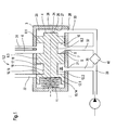
- FIG. 1 illustrates a first embodiment of a Valve device 1 designed according to the invention, in particular in the form of a Pressure control valve 2 based on a section of a hydraulic system.
- the valve device 1 comprises a valve housing 3 and a valve piston 4.
- the Valve piston 4 is slidably mounted in valve housing 3.
- the valve device 1 comprises at least one inlet 5 and at least one outlet 6, which with is connectable to a consumer.
- the connection between the inlet 5 and the Process 6 takes place via a working chamber 7.
- the working chamber 7 is in the case represented by areas of different diameters 8.1 and 8.2 and 8.3 formed on the valve piston 4.
- the individual chambers are realized according to a preferred embodiment by the different dimensions of the piston in the radial direction.
- the areas 8.1 and 8.3 are designed with regard to their diameter such that the valve piston 4 is guided tightly in the valve housing 3 in these areas.
- the area 8.2 has a smaller diameter than the two adjacent areas 8.1 and 8.3.
- the control edges 9 and 10 formed thereby and the outer circumference of the valve piston 4 in the area 8.2 describe the working chamber 7. According to the position of the valve piston 4 in the valve housing 3 relative to the inlet 5 and the outlet 6, the working chamber 7 serves to connect the inlet 5 and the sequence 6, which can be coupled to a consumer.
- connection between the inlet 5 and the outlet 6 are arranged offset in the axial direction from one another in the case shown, so that the valve piston 4 assumes a position in the unloaded state, which blocks the connection between the inlet 5 and the outlet 6, in detail the outlet 6 is covered by the area 8.3, while the area 8.2 is above the inlet 5 and thus there is a connection between the inlet 5 and the working chamber 7.
- the valve piston 4 is then pressed with increasing pressure in a pressure chamber 26 in the direction of the outlet 6 until the connection between inlet 5 and outlet 6 is released.
- the valve piston 4 is displaced against a spring device 11, which is arranged between the valve housing 3 and the valve piston 4 and, in the unloaded state, ie when the working medium is not supplied to the consumer, conveys the valve piston into a position due to the spring force which blocks the outlet 6.
- the spring device 11 is designed as a compression spring.
- a filter, heat exchanger or other functional element 40 is provided in the inflow line 29 coupled to the inlet 5, which are acted upon with the entire flow rate, the actual function as a pressure control valve or pressure relief valve only being realized within the valve device by the outflow of operating medium , wherein the outflow takes place only after the inlet in the valve device.
- the invention provides that the valve piston 4 maintains the working pressure in the system, that is to say in the connection to the outlet 6 that can be coupled to a consumer, by flowing off the medium in front of the upstream elements, such as z. B. filter and / or heat exchanger controls.
- the valve piston 4 has two further areas of different diameters, here 12.1 and 12.2, which in the illustrated case adjoin the area of different diameters 8.3.
- the spring device 11 is arranged between the valve housing 3 and the end face 13 of the valve piston 4 which faces the valve housing and which is formed by the end face 14 in the region of different diameters 12.1.
- the two areas of different diameters 12.1 and 12.2 also form control edges, a first control edge 15, which is formed by the end face 16 directed away from the spring device 11 at the area 12.1 and a second control edge 17, which is formed by the end face 18 adjacent to the area 12.2 Area of different diameters 8.3 is formed.
- the control edges 15 and 17 and the outer circumference 19 in the area 12.2 form an outflow chamber 20.
- the control edges 15 and 17 serve to separate the space 20 from 7.
- the outflow edge 20 can be coupled to an outflow inlet 21 arranged in the valve housing 3 and an outflow outlet 22. The coupling takes place here via the position of the valve piston 4.
- the arrangement of the areas of different diameters in the valve piston 4 or the function assignment to one another can also be done differently.
- the outflow inlet 21 can be connected in the flow direction upstream of the functional elements 40, such as, for example, heat exchangers or filters, to the inflow line 29 via a line section.
- the outflow inlet 21 and the outflow outlet 22 in the valve housing 3, viewed in the axial direction, are arranged offset to one another.
- the valve piston 4 also has a further section with a smaller diameter than the valve housing 3, in particular the interior 23 of the valve housing 3. This section of smaller diameter is designated by 24 and forms the end face 25 of the valve piston 4, which is directed away from the spring device 11.
- This region of smaller diameter 24 thus describes the adjoining region 8.1 and the interior 23 of the valve housing 3 as a further chamber, which is also used as a pressure chamber 26 is referred to, which can be coupled to the operating material inflow, the coupling taking place analogously to that of the working chamber 7 and the connection to the inflow line 29 behind the functional elements 40 heat exchanger, filter etc. is provided.
- this chamber is solely responsible for the regulation, ie the desired piston movement.
- the area of smaller diameter 24 is only necessary if the inflow 28 comes from the side, since otherwise the control inflow 28 would be closed forever if there was no pressure. This means that the inflow 28 is always kept open.
- the area of smaller diameter 24 could be dispensed with if the inlet 28 were to run from the right in the radial direction in the axial direction instead of as shown in FIG. 1.
- the arrangement of the pressure chamber 26 in the valve housing can also take place differently in the axial direction with respect to the working chamber 7, for example on the side on which the energy storage device is provided in FIG. 1. This is then assigned analogously to the other piston end (for example tension spring instead of compression spring).
- the mode of operation is as follows:
- valve piston 4 In the fully relieved state, the valve piston 4 is driven solely by the force the spring device 11 applied to its end face 13. This is located thereby in a position in which the end face 25 on the interior 23 abuts in the axial direction end face 27 in the valve housing 3, as shown in Figure 3, or forms an intermediate space with this.
- the individual areas of different cross-section or diameter 8.1 to 8.3, 12.1, 12.2 and 24 are such in terms of their axial extension designed that the discharge flow 22 is blocked in the unloaded state.
- the Outflow inlet 21 and inlet 5 are, however, with the outflow chamber 20 or the working chamber 7 coupled. This also applies to another one, here provided second inlet 28 to the pressure chamber 26, which to the inflow line 29 is coupled behind the functional elements 40, filters, heat exchangers etc.
- resources are fed into the Working chamber 20 and pressure chamber 26 via inlet 5 and inlet 28 directed.
- a pressure builds up in the pressure chamber 26.
- the figure 1 may also have a further second sequence 31 be provided which the first working chamber 7 with another Consumer couples.
- the second outlet 31 is in the axial direction at one Level arranged with the inlet 5, which is why with the connecting line 32 the inflow line 29 to the inflow 5 of operating equipment via the first working chamber 7 even without shifting the piston 4, operating resources directly to the second Process 31 and thus consumer is directed.
- the sequence 6 is in this state still closed.
- the drain 31 forms a small throttled drain here.
- a higher pressure is set in the pressure chamber 26.
- the drain 6 is open. There is thus the possibility of regulating the working pressure in two stages. It is conceivable, but not shown here, to provide several throttled devices and / or unthrottled outputs in any position, depending on the desired Grading of the working pressure control. The additional (throttled) outputs are also used to control the flow rate for a particular Consumer uses its full amount only when opening the large one Should receive exhaust hole, but previously supplied to a reduced extent must become. Corresponding to the one in this coupled with the second process 31 The pressure which then arises is then also the pressure chamber 26 with equipment via a connecting line 33 between the second inlet 28 and the inflow line 29 in the flow direction behind the functional elements 40, filters or heat exchangers.
- the resource in the Pressure chamber 26 causes a force on the valve piston 4, which counter to the Spring force of the spring device 11 is directed. If the pressure in the Pressure chamber 26 so large that the resulting force on the Valve piston 4 is greater than the force applied by the spring 11, the Spring device 11 compressed by the valve piston 4 against the Spring device 11 is moved. The connection between the Inlet 5 and also the outlet 6 released, but the connection between the outflow chamber 20 and the outflow outlet 22 still is blocked. This is due to the appropriate design and Dimensioning of the individual areas of different diameters in axial direction and thus arrangement of the individual control edges in the axial Direction realized.
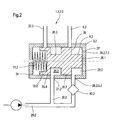
- FIG. 2 illustrates using a very highly schematic diagram Representation of a further second possibility of constructive design of a valve device 1.2 according to the invention, which by a very compact Design is characterized and in particular the connection to one Consumers in a particularly compact manner due to the small size can be executed.
- the basic structure and the basic principle corresponds in essential to that described in Figure 1, which is why for the same elements the same reference numerals are used.
- the Pressure chamber 26.2 quasi formed by the working chamber 7.2.
- the inflow 28.2 corresponds to the inflow 5.2.
- valve device 1.2 comprises which is in the form of a pressure control valve 2.2, a valve housing 3.2 and a valve piston 4.2, which is displaceable in the axial direction on the valve housing is guided, the leadership is pressure and liquid tight.
- Valve piston 4.2 and valve housing 3.2 or the interior 23.2 is one Spring device 11.2 arranged. This is supported on an end face 34 of the Interior 23.2 and the end face 13.2 facing this end face 34 of the valve piston 4.2.
- the valve piston 4.2 is here through four areas characterized different diameters, these are here with 35.1 to 35.4 designated.
- the areas 35.2 and 35.4 are essentially the same Diameter as the interior 23.2 of the valve housing 3.2 executed.
- This both areas 35.2 and 35.4 are pressure-tight and liquid-tight in the Housing 3.2 out. Between the areas 35.2 and 35.4 there is an area 35.3 arranged, which has a smaller diameter and thus with its Outer circumference 36 and those facing each other at areas 35.2 and 35.4 End faces 37 and 38 form a discharge chamber 20.2, which in one Functional state of the valve device 1.2, in particular the valve piston 4.2, connects an outflow inlet 21.2 to an outflow channel 22.2.
- the outflow chamber 20.2 is via the outflow inlet 21.2 with the inflow line 29.2 coupled, this coupling taking place via the connecting line 30.2 and the connecting line 30.2 in the flow direction in the inflow line 29.2 in front of the functional elements 40, e.g. the heat exchanger and / or the filter the inflow line 29.2 is coupled.
- Both connections 5.2 and 6.2 as well as the outflow inlet 21.2 and the Outflow outlet 22.2 are viewed in the case shown in the axial direction offset to each other, d. H. arranged in different levels.
- the Connection between the inlet 5.2 and the outlet 6.2 takes place via a Working chamber 7.2, which extends from the end face 25.2 of the interior 23.2, which faces the piston 4.2 and the outer dimensions of the Valve piston 4.2 is formed in the area 35.1.
- the Working space 7.2 from one, from area 35.2 to end face 27 on interior 23 facing end face 39 and the outer dimensions in the area 35.1 and limited the interior 23.2.
- the area 35.2 forms a control edge, in particular the transition between area 35.2 and area 35.1, which releases or blocks the cross-section for sequence 6.2.
- valve device 1.2 The functioning of the valve device 1.2 can be described as follows: In the unloaded state, the valve piston 4 is in a position in which the outflow 6.2 and the outflow outflow 22.2 are blocked.
- the inflow line 29.2 is connected via a connecting line 30.2, which is arranged in front of the functional elements 40, such as filters or heat exchangers, to the outflow inlet 21.2, while the inflow line 29.2 is connected behind the functional elements, such as filters or heat exchangers, to the inlet 5.2 to the working chamber 7.2 which simultaneously forms the inlet 28.2 to the pressure chamber 26.2, which is formed by the working chamber 7.2.
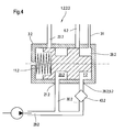
- Figure 4 illustrates another possible embodiment of a valve device 1.2 according to Figure 2 with two processes 6.2 and 31 in the basic state, d. H. unloaded Status.
- the basic structure corresponds to that described in FIG. except for the arrangement of processes 6.2 and 31, which is why the same Elements have the same reference numerals.
- the order of 6.2 takes place compared to the inlet 5.2 as described in Figure 2.
- the additional Drain 31 can either also in offset levels from inlet 5.2 or a common level can be arranged. With this solution is also in Basic state is always an inflow and thus the expiration of the 31st coupled consumption guaranteed.
- FIG. 5 illustrates a further modification of an embodiment according to FIG Ensuring the supply of the consumer even when the load is off.
- This also only has a sequence 6.2, which, however, is different from that in Figure 2 is shown arranged in one plane with the inlet 5.2.
- the rest Basic structure corresponds to that described in Figure 2, which is why for the same Elements have the same reference numerals.
- the arrangement of this a process 6.2 can, however, also be offset from the level of the supply 5.2 take place, the offset in the direction of the end face 27 of the housing 3.
- Figure 6 illustrates a further advantageous embodiment of a basic version 2 with two processes 6.2 and 31, at least one in the axial Direction viewed is offset from the inlet 5.2.
- the pressure chamber 26.2 and 7.2 of a working chamber Chamber formed. This is from the valve piston 4.2 and one in the valve housing 3.2 arranged stationary insert element 41 is formed.
- the valve piston 4.2 is guided on this, for which purpose the valve piston 4.2 has a recess 42.
- This solution offers the advantage of providing small areas for realization the displacement of the valve piston 4.2 when pressurized and further Advantages with regard to the required dimensioning of the spring device 11.2.
- the flow chamber 20.2 is arranged as in the others Figures described designs. This also applies to how it works.
Landscapes
- Engineering & Computer Science (AREA)
- Physics & Mathematics (AREA)
- Fluid Mechanics (AREA)
- Analytical Chemistry (AREA)
- Automation & Control Theory (AREA)
- Chemical & Material Sciences (AREA)
- General Physics & Mathematics (AREA)
- Mechanical Engineering (AREA)
- General Engineering & Computer Science (AREA)
- Safety Valves (AREA)
- Control Of Fluid Pressure (AREA)
- Valve-Gear Or Valve Arrangements (AREA)
- Fluid-Driven Valves (AREA)
Abstract
Description
- Fig. 1
- verdeutlicht in schematisch vereinfachter Darstellung eine erste Ausgestaltungsmöglichkeit einer erfindungsgemäß gestalteten Ventileinrichtung;
- Fig. 2
- verdeutlicht in schematisch vereinfachter Darstellung eine zweite Ausgestaltungsmöglichkeit einer erfindungsgemäß gestalteten Ventileinrichtung;
- Fig. 3
- verdeutlicht die Ventileinrichtung gemäß Figur 1 in der Grundstellung;
- Fig. 4
- verdeutlicht eine Ausführung der Ventileinrichtung gemäß Figur 2 mit einem weiteren Ablauf;
- Fig. 5
- verdeutlicht eine Ausführung der Ventileinrichtung gemäß Figur 2 mit einem Ablauf und Versatz dessen, zum Zulauf in axialer Richtung;
- Fig. 6
- verdeutlicht eine weitere Abwandlung der Ausführung gemäß Figur 2.
Die Bereiche 8.1 und 8.3 sind hinsichtlich ihres Durchmessers derart ausgeführt, dass der Ventilkolben 4 in diesen Bereichen dicht im Ventilgehäuse 3 geführt wird. Der Bereich 8.2 weist einen geringeren Durchmesser als die beiden benachbarten Bereiche 8.1 und 8.3 auf. Die dadurch gebildeten Steuerkanten 9 und 10 sowie der Außenumfang des Ventilkolbens 4 im Bereich 8.2 beschreiben dabei die Arbeitskammer 7. Entsprechend der Stellung des Ventilkolbens 4 im Ventilgehäuse 3 gegenüber dem Zulauf 5 und dem Ablauf 6 dient die Arbeitskammer 7 der Verbindung zwischen dem Zulauf 5 und dem Ablauf 6, der mit einem Verbraucher koppelbar ist. Dabei sind die Anschlüsse zwischen dem Zulauf 5 und dem Ablauf 6 im dargestellten Fall in axialer Richtung zueinander versetzt angeordnet, so dass der Ventilkolben 4 im entlasteten Zustand eine Stellung einnimmt, welche die Verbindung zwischen dem Zulauf 5 und dem Ablauf 6 sperrt, im einzelnen wird dabei der Ablauf 6 durch den Bereich 8.3 verdeckt, während der Bereich 8.2 über dem Zulauf 5 steht und damit eine Verbindung zwischen dem Zulauf 5 und der Arbeitskammer 7 gegeben ist. Bei Zuströmen des Betriebsmittels über den Zulauf 5 wird dann mit wachsendem Druck in einer Druckkammer 26 der Ventilkolben 4 in Richtung des Ablaufes 6 gedrückt, bis die Verbindung zwischen Zulauf 5 und Ablauf 6 freigegeben wird. Der Ventilkolben 4 wird dabei gegen eine Federeinrichtung 11 verschoben, welche zwischen dem Ventilgehäuse 3 und dem Ventilkolben 4 angeordnet ist und im entlasteten Zustand, d. h. bei Nichtzufuhr von Arbeitsmittel zum Verbraucher den Ventilkolben aufgrund der Federkraft in eine Stellung befördert, welche den Ablauf 6 versperrt. Die Federeinrichtung 11 ist dabei als Druckfeder ausgeführt. Bei konventionellen Lösungen sind in der mit dem Zulauf 5 gekoppelten Zuflussleitung 29 ein Filter, Wärmetauscher oder anderes Funktionselement 40 vorgesehen, welche mit der gesamten Durchflussmenge beaufschlagt werden, wobei die eigentliche Funktion als Druckregelventil bzw. Druckbegrenzungsventil erst innerhalb der Ventileinrichtung durch Abströmen von Betriebsmedium realisiert wird, wobei das Abströmen erst nach dem Zulauf in der Ventileinrichtung erfolgt. Zur Vermeidung des damit unnötig verbundenen Durchströmens der Funktionselemente, Filter und Wärmetauscher mit dem Betriebsmedium ist erfindungsgemäß vorgesehen, dass der Ventilkolben 4 den Arbeitsdruck im System, d. h. in dem mit einem Verbraucher koppelbaren Anschluss am Ablauf 6 durch Abströmen des Mediums vor den vorgeschalteten Elementen, wie z. B. Filter und/oder Wärmetauscher, steuert. Dazu weist der Ventilkolben 4 zwei weitere Bereiche unterschiedlichen Durchmessers, hier 12.1 und 12.2, auf, welche im dargestellten Fall an den Bereich unterschiedlichen Durchmessers 8.3 angrenzen. Die Federeinrichtung 11 ist dabei zwischen dem Ventilgehäuse 3 und der zum Ventilgehäuse hingewandten Stirnfläche 13 des Ventilkolbens 4, welche von der Stirnfläche 14 am Bereich unterschiedlichen Durchmessers 12.1 gebildet wird, angeordnet. Die beiden Bereiche unterschiedlichen Durchmessers 12.1 und 12.2 bilden des weiteren Steuerkanten, eine erste Steuerkante 15, welche von der von der Federeinrichtung 11 weggerichteten Stirnfläche 16 am Bereich 12.1 gebildet wird und eine zweite Steuerkante 17, die von der an dem Bereich 12.2 angrenzenden Stirnfläche 18 am Bereich unterschiedlichen Durchmessers 8.3 gebildet wird. Die Steuerkanten 15 und 17 sowie der Außenumfang 19 im Bereich 12.2 bilden eine Abströmkammer 20. Die Steuerkanten 15 und 17 dienen dabei der Trennung des Raumes 20 von 7. Die Abströmkante 20 ist mit einem im Ventilgehäuse 3 angeordneten Abströmzulauf 21 und einem Abströmablauf 22 koppelbar. Die Kopplung erfolgt hier über die Stellung des Ventilkolbens 4. Die Anordnung der Bereiche unterschiedlichen Durchmessers im Ventilkolben 4 bzw. die Funktionszuordnung zueinander kann auch anders erfolgen. Wesentlich ist jedoch, dass der Abströmzulauf 21 in Strömungsrichtung vor den Funktionselementen 40, wie beispielsweise Wärmetauscher oder Filter über einen Leitungsabschnitt mit der Zuflussleitung 29 verbindbar ist. Auch hier sind Abströmzulauf 21 und Abströmablauf 22 im Ventilgehäuse 3 in axialer Richtung betrachtet versetzt zueinander angeordnet. Bei der in der Figur 1 dargestellten Ausführung weist der Ventilkolben 4 ferner einen weiteren Abschnitt mit geringerem Durchmesser als das Ventilgehäuse 3, insbesondere der Innenraum 23 des Ventilgehäuses 3, auf. Dieser Abschnitt geringeren Durchmessers ist mit 24 bezeichnet und bildet die, von der Federeinrichtung 11 weggerichtete Stirnfläche 25 des Ventilkolbens 4. Damit beschreibt dieser Bereich geringeren Durchmessers 24 mit dem angrenzenden Bereich 8.1 sowie dem Innenraum 23 des Ventilgehäuses 3 eine weitere Kammer, die auch als Druckkammer 26 bezeichnet wird, welche mit dem Betriebsmittelzufluss koppelbar ist, wobei die Kopplung analog zu der der Arbeitskammer 7 erfolgt und die Anbindung an die Zuflußleitung 29 hinter den Funktionselementen 40 Wärmetauscher, Filter etc. vorgesehen ist. Bei der Ausführung mit gleichbleibender Gehäuseinnenkammer bzw. Gehäuseinnenraum 23 ist diese Kammer ausschließlich für die Regelung, d. h. gewünschte Kolbenbewegung, verantwortlich. Der Bereich geringeren Durchmessers 24 ist nur notwendig, wenn der Zufluss 28 von der Seite kommt, da sich sonst der Regelzufluß 28 für immer verschließen würde, wenn einmal kein Druck anliegt. Dies bedeutet, dass der Zufluss 28 immer offen gehalten wird. Auf den Bereich geringeren Durchmessers 24 könnte verzichtet werden, wenn der Zulauf 28 anstatt wie in Figur 1 dargestellt in radialer Richtung in axialer Richtung von rechts verlaufen würde. Die Anordnung der Druckkammer 26 im Ventilgehäuse kann in axialer Richtung auch anders gegenüber der Arbeitskammer 7 erfolgen, beispielsweise auf der Seite, auf welcher in Figur 1 die Energiespeichereinrichtung vorgesehen ist. Diese ist dann analog dem anderen Kolbenende zuzuordnen (beispielsweise Zugfeder statt Druckfeder).
Im entlasteten Zustand befindet sich der Ventilkolben 4 in einer Stellung, in welcher der Ablauf 6.2 sowie der Abströmablauf 22.2 versperrt sind. Die Zuflussleitung 29.2 ist dabei über eine Verbindungsleitung 30.2, welche vor den Funktionselementen 40, wie beispielsweise Filter oder Wärmetauscher angeordnet ist, mit dem Abströmzulauf 21.2 verbunden, während die Zuflußleitung 29.2 hinter den Funktionselementen, wie Filtern oder Wärmetauschern mit dem Zulauf 5.2 zur Arbeitskammer 7.2 gekoppelt ist, welcher gleichzeitig den Zulauf 28.2 zur Druckkammer 26.2, welche von der Arbeitskammer 7.2 gebildet wird, bildet. Dabei gelangt aufgrund des geringen Widerstandes zuerst Betriebsmittel in die Abströmkammer 20.2 und erst dann, wenn in der Abströmkammer 20.2 ein Druck erreicht wird, der größer ist als der in den Leitungsverbindungen zum Zulauf 5.2 über diesen in die Druckkammer 26.2. Der sich dort aufbauende Druck bewirkt eine Kraft auf den Ventilkolben 4.2, welche zur Verschiebung des Ventilkolbens 4.2 gegen die Federeinrichtung 11.2 führt. Dabei wird zuerst der Ablauf 6.2 freigegeben und damit die Verbindung zwischen dem Zulauf 5.2 und dem Ablauf 6.2 zum Verbraucher. Solange der Druck in der Druckkammer 26.2 dabei einen gewissen Wert nicht überschreitet, erfolgt keine weitere Verschiebung des Ventilkolbens 4.2 und der Abströmablauf 22.2 bleibt versperrt. Überschreitet jedoch der Druck einen bestimmten Wert, wird die Federeinrichtung 11.2 weiter komprimiert und der Abströmablauf 22.2 wird freigegeben, welcher einen Übertritt aus der Zuflussleitung 29.2 zum Abströmablauf 22.2 bewirkt. Dies äußert sich auch im Druck in der Arbeitskammer 7.2, der dann ab diesem Zeitpunkt nicht mehr zunimmt bzw. auch wieder abnehmen kann.
- 1; 1.2
- Ventileinrichtung
- 2; 2.2
- Druckregelventil
- 3; 3.2
- Ventilgehäuse
- 4; 4.2
- Ventilkolben
- 5; 5.2
- Zulauf
- 6; 6.2
- Ablauf
- 7; 7.2
- Arbeitskammer
- 8.1, 8.2, 8.3
- Bereiche unterschiedlichen Durchmessers
- 9
- Steuerkante
- 10
- Steuerkante
- 11
- Federeinrichtung
- 12.1, 12.2
- Bereiche unterschiedlichen Durchmessers
- 13
- Stirnfläche
- 14
- Stirnfläche
- 15
- Steuerkante
- 16
- Stirnfläche
- 17
- Steuerkante
- 18
- Stirnfläche
- 19
- Außenumfang
- 20
- Abströmkammer
- 21; 21.2
- Abströmzulauf
- 22; 22.2
- Abströmablauf
- 23; 23.2
- Innenraum
- 24
- Abschnitt geringeren Durchmessers
- 25
- Stirnfläche
- 26; 26.2
- Druckkammer
- 27
- Stirnfläche
- 28; 28.2
- Zulauf
- 29; 29.2
- Zuflussleitung
- 30; 30.2
- Verbindungsleitung
- 31
- zweiter Ablauf
- 32
- Verbindungsleitung
- 33
- Verbindungsleitung
- 34
- Stirnfläche
- 35.1 bis 35.4
- Bereiche unterschiedlichen Durchmessers
- 36
- Außenumfang
- 37
- Stirnfläche
- 38
- Stirnfläche
- 39
- Stirnfläche
- 40
- Funktionselemente
- 41
- Einsatzelement
- 42
- Ausnehmung
Claims (19)
- Ventileinrichtung (1; 1.2), insbesondere Druckregelventil oder Druckbegrenzungsventil1.1 mit einem Ventilgehäuse (3; 3.2) und einem, im Ventilgehäuse (3; 3.2) relativ zu diesem in axialer Richtung verschiebbaren Steuerkanten (9, 10 17, 15) aufweisenden Ventilkolben (4; 4.2), welcher mit dem Ventilgehäuse (3: 3.2) eine Arbeitskammer bildet;1.2 mit einem der Arbeitskammer (7; 7.2) zugeordneten mit einer Zulaufleitung (29; 29.2) koppelbaren Zulauf (5; 5.2) und wenigstens einem der Arbeitskammer (7; 7.2) zugeordneten Ablauf (6; 6.2), wobei die Freigabe von Zulauf (5; 5.2) und Ablauf (6; 6.2) durch die Stellung des Ventilkolbens (4; 4.2) bedingt ist;
gekennzeichnet durch folgende Merkmale:1.3 mit einer, von den Steuerkanten des Ventilkolbens (4; 4.2) und dem Ventilgehäuse (3;3.2) gebildeten Abströmkammer (20; 20.2);1.4 mit einem Abströmzulauf (21; 21.2) zur Koppelung mit einer, mit der Zuflußleitung (29; 29.2) koppelbaren Verbindungsleitung (30; 30.2) in Strömungsrichtung betrachtet im Bereich vor den Funktionselementen (40) und einem Abströmablauf (22; 22.2);1.5 die Abströmkammer (20; 20.2) ist frei von einer Verbindung zur Arbeitskammer (7; 7.2) und dem der Arbeitskammer (7; 7.2) zugeordneten Zulauf (5; 5.2). - Ventileinrichtung (1; 1.2) nach Anspruch 1, gekennzeichnet durch die folgenden Merkmale:2.1 mit einer zwischen Ventilgehäuse (3; 3.2) und einer zu diesem weisenden Stirnfläche (13) des Ventilkolbens (4; 4.2) angeordneten Energiespeichereinrichtung (11);2.2 mit einer vom Ventilkolben (4; 4.2) und dem Ventilgehäuse (3; 3.2) begrenzten und hinsichtlich der Abmessungen veränderlichen Druckkammer (26; 26.2) zur Beaufschlagung des Ventilkolbens (4; 4.2) auf seiner der Energiespeichereinrichtung (11) weggerichteten Stimseite (25; 25.2) und einem Zulauf (28;28.2) für das Druckmittel.
- Ventileinrichtung (1; 1.2) nach einem der Ansprüche 1 oder 2, dadurch gekennzeichnet, dass die Dimensionierung von Ventilkolben (4; 4.2), Steuerkanten (9, 10, 17, 15) derart erfolgt, dass in keiner Funktionsstellung der Zulauf (5; 5.2) zur Arbeitskammer (7; 7.2) und der Abströmzulauf (21; 21.2) gemeinsam in die Abströmkammer (20; 20.2) münden.
- Ventileinrichtung (1; 1.2) nach einem der Ansprüche 1 bis 3, dadurch gekennzeichnet, dass der Abströmzulauf (21; 21.2) und der Abströmablauf (22; 22.2) in axialer Richtung versetzt zueinander angeordnet sind.
- Ventileinrichtung (1;1.2) nach einem der Ansprüche 1 bis 4, dadurch gekennzeichnet, dass der Innenraum (23; 23.2) des Ventilgehäuses (3; 3.2) in axialer Richtung derart bemessen ist, dass im entlasteten oder noch teilweise vorgespannten Zustand der Energiespeichereinheit (11) die von der Energiespeichereinrichtung (11) weggerichtete Stirnfläche (25) des Ventilkolbens (4; 4.2) an der zum Ventilkolben (4; 4.2) gerichteten Stirnfläche (27) des Ventilgehäuses (3; 3.2) anliegt.
- Ventileinrichtung (1; 1.2) nach einem der Ansprüche 1 bis 4, dadurch gekennzeichnet, dass der Innenraum (23; 23.2) des Ventilgehäuses (3; 3.2) in axialer Richtung derart bemessen ist, dass im entlasteten Zustand der Energiespeichereinheit (11) ein Zwischenraum zwischen Ventilgehäuse (3; 3.2) und von der Energiespeichereinheit (11) weggerichteter Stirnfläche (25) des Ventilkolbens (4; 4.2) gebildet wird.
- Ventileinrichtung (1; 1.2) nach einem der Ansprüche 5 oder 6, dadurch gekennzeichnet, dass die von der Energiespeichereinheit (11) weggerichtete Stirnfläche (25.2) des Ventilkolbens (4; 4.2) von einem Bereich (24) mit geringeren äußeren Abmessungen als die des Innenraumes (23; 23.2) des Ventilkolbens (4; 4.2) gebildet wird.
- Ventileinrichtung (1; 1.2) nach Anspruch 5 oder 6, dadurch gekennzeichnet, dass die von der Energiespeichereinheit (11) weggerichtete Stirnfläche (25) des Ventilkolbens (4; 4.2) von einem Bereich gleicher Außenabmessungen wie die Abmessungen des Innenraumes (23; 23.2) des Ventilkolbens (4; 4.2) gebildet wird.
- Ventileinrichtung (1.2) nach einem der Ansprüche 2 bis 8, gekennzeichnet durch die folgenden Merkmale:9.1 die Druckkammer (26.2) wird von der Arbeitskammer (7.2) gebildet;9.2 der Zulauf (28.2) für Druckmittel wird vom Zulauf (5.2) zur Arbeitskammer (7.2) gebildet.
- Ventileinrichtung (1.2) nach Anspruch 9, gekennzeichnet durch die folgenden Merkmale:10.1 der Ventilkolben (4.2) weist Bereiche unterschiedlichen Durchmessers auf, welche die Steuerkanten zur Begrenzung von Abströmkammer (20; 20.2), Arbeits- und Druckkammer (7.2; 26.2) bilden;10.2 die Arbeits- und Druckkammer (7.2; 26.2) wird von der vom Energiespeicher (11) weggerichteten Stirnfläche und dem Ventilgehäuse (3.2) begrenzt;10.3 der Zulauf und Ablauf (5.2; 28.2; 6.2) sind in axialer Richtung in einer Ebene oder versetzt zueinander angeordnet, wobei der Ablauf (6.2) in axialer Richtung ausgehend von der Energiespeichereineit (11) betrachtet vor dem Zulauf (5.2; 28.2) liegt.
- Ventileinrichtung (1) nach einem der Ansprüche 1 bis 8, dadurch gekennzeichnet, dass die Druckkammer (26) und die Arbeitskammer (7) von unterschiedlichen Kammern gebildet werden und der Zulauf (28) für Druckmittel dem Zulauf (5) zur Arbeitskammer (7) in axialer Richtung von der Energiespeichereinheit (11) aus betrachtet nachgeordnet ist.
- Ventileinrichtung (1) nach Anspruch 11, gekennzeichnet durch die folgenden Merkmale:12.1 der Ventilkolben (4) weist Bereiche (8.1; 8.2; 8.3; 12.1; 12.2; 24) unterschiedlichen Durchmessers auf, welche die Steuerkanten (15; 17; 9; 10) zur Begrenzung von Abströmkammer (20), Arbeitskammer (7) und Druckkammer (26) bilden;12.2 die Druckkammer (26) wird von der vom Energiespeicher (11) weggerichteten Stirnfläche (25) des Ventilkolbens (4) und dem Ventilgehäuse (3) begrenzt;12.3 der Zulauf (5) und Ablauf (6) sind in axialer Richtung in einer Ebene oder versetzt zueinander angeordnet, wobei der Ablauf (6) in axialer Richtung ausgehend von der Energiespeichereineit (1) betrachtet vor dem Zulauf (5) liegt.
- Ventileinrichtung (1) nach einem der Ansprüche 11 oder 12, dadurch gekennzeichnet, dass dem Arbeitsraum (7) ein zweiter Ablauf (31) zugeordnet ist, welcher in einer axialen Ebene mit dem Zulauf (5) oder nur geringfügig versetzt zu diesem angeordnet ist.
- Ventileinrichtung (1; 1.2) nach einem der Ansprüche 2 bis 13, dadurch gekennzeichnet, dass die Energiespeichereinrichtung (11) eine Feder umfaßt.
- Ventileinrichtung (1; 1.2) nach einem der Ansprüche 1 bis 10, dadurch gekennzeichnet, dass die Energiespeichereinrichtung (11) eine elastische Membran umfasst.
- Hydraulisches System16.1 mit mindestens einem Verbraucher;16.2 mit einer Zuflussleitung (29; 29.2) zum Verbraucher;16.3 mit Funktionselementen (40) in der Zuflußleitung (29; 29.2);16.4 mit einer Ventileinrichtung (1; 1.2) gemäß einem der Ansprüche 1 bis 15 zur Druckbegrenzung oder Regelung.
- Hydraulisches System nach Anspruch 16, dadurch gekennzeichnet, dass die Funktionselemente einen Wärmetauscher und/oder eine Filtereinrichtung umfassen.
- Hydraulisches System nach Anspruch 17, dadurch gekennzeichnet, dass der Wärmetauscher in der Zuflussleitung (29; 29.2) vor dem Abströmzulauf (21; 21.2) angeordnet ist.
- Hydraulisches System nach Anspruch 17, dadurch gekennzeichnet, dass alle Funktionselemente in der Zuflussleitung (29; 29.2) dem Abströmzulauf (21; 21.2) und dem Zulauf (5; 5.2) zur Arbeitskammer (7; 7.2) angeordnet sind.
Applications Claiming Priority (2)
| Application Number | Priority Date | Filing Date | Title |
|---|---|---|---|
| DE10303418 | 2003-01-29 | ||
| DE10303418A DE10303418B4 (de) | 2003-01-29 | 2003-01-29 | Ventileinrichtung |
Publications (3)
| Publication Number | Publication Date |
|---|---|
| EP1443221A2 true EP1443221A2 (de) | 2004-08-04 |
| EP1443221A3 EP1443221A3 (de) | 2005-06-08 |
| EP1443221B1 EP1443221B1 (de) | 2008-05-07 |
Family
ID=32603017
Family Applications (1)
| Application Number | Title | Priority Date | Filing Date |
|---|---|---|---|
| EP04001514A Expired - Lifetime EP1443221B1 (de) | 2003-01-29 | 2004-01-24 | Ventileinrichtung und hydraulisches System |
Country Status (3)
| Country | Link |
|---|---|
| EP (1) | EP1443221B1 (de) |
| AT (1) | ATE394602T1 (de) |
| DE (2) | DE10303418B4 (de) |
Cited By (1)
| Publication number | Priority date | Publication date | Assignee | Title |
|---|---|---|---|---|
| CN103038519A (zh) * | 2010-06-11 | 2013-04-10 | 空中客车作业有限公司 | 顺序阀组件以及用于操作顺序阀组件的方法 |
Family Cites Families (3)
| Publication number | Priority date | Publication date | Assignee | Title |
|---|---|---|---|---|
| US4192337A (en) * | 1978-08-07 | 1980-03-11 | The Cessna Aircraft Company | Priority flow valve |
| US4244389A (en) * | 1978-09-08 | 1981-01-13 | Jidoshakiki Co., Ltd. | Flow control valve |
| JPS58146168U (ja) * | 1982-03-26 | 1983-10-01 | 自動車機器株式会社 | 流量制御弁 |
-
2003
- 2003-01-29 DE DE10303418A patent/DE10303418B4/de not_active Expired - Fee Related
-
2004
- 2004-01-24 DE DE502004007016T patent/DE502004007016D1/de not_active Expired - Lifetime
- 2004-01-24 EP EP04001514A patent/EP1443221B1/de not_active Expired - Lifetime
- 2004-01-24 AT AT04001514T patent/ATE394602T1/de not_active IP Right Cessation
Cited By (2)
| Publication number | Priority date | Publication date | Assignee | Title |
|---|---|---|---|---|
| CN103038519A (zh) * | 2010-06-11 | 2013-04-10 | 空中客车作业有限公司 | 顺序阀组件以及用于操作顺序阀组件的方法 |
| CN103038519B (zh) * | 2010-06-11 | 2016-01-20 | 空中客车作业有限公司 | 顺序阀组件以及用于操作顺序阀组件的方法 |
Also Published As
| Publication number | Publication date |
|---|---|
| EP1443221B1 (de) | 2008-05-07 |
| DE502004007016D1 (de) | 2008-06-19 |
| ATE394602T1 (de) | 2008-05-15 |
| DE10303418A1 (de) | 2004-08-19 |
| EP1443221A3 (de) | 2005-06-08 |
| DE10303418B4 (de) | 2006-02-16 |
Similar Documents
| Publication | Publication Date | Title |
|---|---|---|
| EP2382520B1 (de) | Proportional-druckregelventil und seine verwendung für hydraulisch betätigbare kupplungen | |
| DE3413866C2 (de) | Hydrostatisches Antriebssystem | |
| EP2960561B1 (de) | Hydraulikventil | |
| EP2488764B1 (de) | Ventilanordnung | |
| DE102004012831B4 (de) | Entkoppeltes Rückschlag-Druckbegrenzungsventil | |
| EP2054691A1 (de) | Bypassventil für einen einem hydraulikaggregat nachgeordneten kühler | |
| EP1469235A1 (de) | Hydraulisches Steuer- und Regelsystem sowie Verfahren zum Einstellen von hydraulischen Druckniveaus | |
| DE1750500B2 (de) | Hydraulisches steuersystem mit wenigstens einem hydraulikzylinder | |
| EP0935713A1 (de) | Ventilanordnung und verfahren zur ansteuerung einer derartigen ventilanordnung | |
| EP2669528A2 (de) | Hydrostatische Ventilanordnung und hydrostatische Steueranordnung mit der Ventilanordnung | |
| WO2008025396A1 (de) | Ls-steueranordnung | |
| EP1984629B1 (de) | Hydraulische steueranordnung mit regeneration und senkbremsventil | |
| DE2843576A1 (de) | Pumpensteueranordnung | |
| WO2003087585A1 (de) | Hydraulische steueranordnung in load-sensing technik | |
| EP1443221B1 (de) | Ventileinrichtung und hydraulisches System | |
| DE102022103492B4 (de) | Drosselventilanordnung für hydrostatische einheiten | |
| EP1996820B1 (de) | Hydraulische ventilanordnung | |
| EP2241764B1 (de) | Sitzventil mit Umlaufventil- und Druckwaagefunktion | |
| EP3309644B1 (de) | Ventilvorrichtung sowie druckregelsystem mit einer solchen ventilvorrichtung | |
| EP2337980B1 (de) | Wegeventil | |
| WO2002093018A1 (de) | Ventilanordnung | |
| EP1736671A2 (de) | LS-Steueranordnung und LS-Wegeventil | |
| EP3788284B1 (de) | Vorrichtung zur regelung des drucks von fluiden | |
| WO2005111430A1 (de) | Hydraulik-ventilanordnung, insbesondere wasserhydraulik-ventilanordnung | |
| EP1552140B1 (de) | Volumenstromregelventil |
Legal Events
| Date | Code | Title | Description |
|---|---|---|---|
| PUAI | Public reference made under article 153(3) epc to a published international application that has entered the european phase |
Free format text: ORIGINAL CODE: 0009012 |
|
| AK | Designated contracting states |
Kind code of ref document: A2 Designated state(s): AT BE BG CH CY CZ DE DK EE ES FI FR GB GR HU IE IT LI LU MC NL PT RO SE SI SK TR |
|
| AX | Request for extension of the european patent |
Extension state: AL LT LV MK |
|
| PUAL | Search report despatched |
Free format text: ORIGINAL CODE: 0009013 |
|
| AK | Designated contracting states |
Kind code of ref document: A3 Designated state(s): AT BE BG CH CY CZ DE DK EE ES FI FR GB GR HU IE IT LI LU MC NL PT RO SE SI SK TR |
|
| AX | Request for extension of the european patent |
Extension state: AL LT LV MK |
|
| RIC1 | Information provided on ipc code assigned before grant |
Ipc: 7F 15B 11/16 B Ipc: 7F 16K 17/04 B Ipc: 7F 15B 21/04 A |
|
| 17P | Request for examination filed |
Effective date: 20051118 |
|
| AKX | Designation fees paid |
Designated state(s): AT BE BG CH CY CZ DE DK EE ES FI FR GB GR HU IE IT LI LU MC NL PT RO SE SI SK TR |
|
| 17Q | First examination report despatched |
Effective date: 20060816 |
|
| GRAP | Despatch of communication of intention to grant a patent |
Free format text: ORIGINAL CODE: EPIDOSNIGR1 |
|
| GRAS | Grant fee paid |
Free format text: ORIGINAL CODE: EPIDOSNIGR3 |
|
| GRAA | (expected) grant |
Free format text: ORIGINAL CODE: 0009210 |
|
| AK | Designated contracting states |
Kind code of ref document: B1 Designated state(s): AT BE BG CH CY CZ DE DK EE ES FI FR GB GR HU IE IT LI LU MC NL PT RO SE SI SK TR |
|
| REG | Reference to a national code |
Ref country code: GB Ref legal event code: FG4D Free format text: NOT ENGLISH |
|
| REG | Reference to a national code |
Ref country code: CH Ref legal event code: EP |
|
| REG | Reference to a national code |
Ref country code: IE Ref legal event code: FG4D Free format text: LANGUAGE OF EP DOCUMENT: GERMAN |
|
| REF | Corresponds to: |
Ref document number: 502004007016 Country of ref document: DE Date of ref document: 20080619 Kind code of ref document: P |
|
| PG25 | Lapsed in a contracting state [announced via postgrant information from national office to epo] |
Ref country code: SI Free format text: LAPSE BECAUSE OF FAILURE TO SUBMIT A TRANSLATION OF THE DESCRIPTION OR TO PAY THE FEE WITHIN THE PRESCRIBED TIME-LIMIT Effective date: 20080507 |
|
| PG25 | Lapsed in a contracting state [announced via postgrant information from national office to epo] |
Ref country code: FI Free format text: LAPSE BECAUSE OF FAILURE TO SUBMIT A TRANSLATION OF THE DESCRIPTION OR TO PAY THE FEE WITHIN THE PRESCRIBED TIME-LIMIT Effective date: 20080507 Ref country code: ES Free format text: LAPSE BECAUSE OF FAILURE TO SUBMIT A TRANSLATION OF THE DESCRIPTION OR TO PAY THE FEE WITHIN THE PRESCRIBED TIME-LIMIT Effective date: 20080818 Ref country code: NL Free format text: LAPSE BECAUSE OF FAILURE TO SUBMIT A TRANSLATION OF THE DESCRIPTION OR TO PAY THE FEE WITHIN THE PRESCRIBED TIME-LIMIT Effective date: 20080507 |
|
| NLV1 | Nl: lapsed or annulled due to failure to fulfill the requirements of art. 29p and 29m of the patents act | ||
| REG | Reference to a national code |
Ref country code: IE Ref legal event code: FD4D |
|
| PG25 | Lapsed in a contracting state [announced via postgrant information from national office to epo] |
Ref country code: SE Free format text: LAPSE BECAUSE OF FAILURE TO SUBMIT A TRANSLATION OF THE DESCRIPTION OR TO PAY THE FEE WITHIN THE PRESCRIBED TIME-LIMIT Effective date: 20080807 Ref country code: CZ Free format text: LAPSE BECAUSE OF FAILURE TO SUBMIT A TRANSLATION OF THE DESCRIPTION OR TO PAY THE FEE WITHIN THE PRESCRIBED TIME-LIMIT Effective date: 20080507 Ref country code: DK Free format text: LAPSE BECAUSE OF FAILURE TO SUBMIT A TRANSLATION OF THE DESCRIPTION OR TO PAY THE FEE WITHIN THE PRESCRIBED TIME-LIMIT Effective date: 20080507 Ref country code: IE Free format text: LAPSE BECAUSE OF FAILURE TO SUBMIT A TRANSLATION OF THE DESCRIPTION OR TO PAY THE FEE WITHIN THE PRESCRIBED TIME-LIMIT Effective date: 20080507 Ref country code: PT Free format text: LAPSE BECAUSE OF FAILURE TO SUBMIT A TRANSLATION OF THE DESCRIPTION OR TO PAY THE FEE WITHIN THE PRESCRIBED TIME-LIMIT Effective date: 20081007 |
|
| PG25 | Lapsed in a contracting state [announced via postgrant information from national office to epo] |
Ref country code: SK Free format text: LAPSE BECAUSE OF FAILURE TO SUBMIT A TRANSLATION OF THE DESCRIPTION OR TO PAY THE FEE WITHIN THE PRESCRIBED TIME-LIMIT Effective date: 20080507 Ref country code: RO Free format text: LAPSE BECAUSE OF FAILURE TO SUBMIT A TRANSLATION OF THE DESCRIPTION OR TO PAY THE FEE WITHIN THE PRESCRIBED TIME-LIMIT Effective date: 20080507 |
|
| PLBE | No opposition filed within time limit |
Free format text: ORIGINAL CODE: 0009261 |
|
| STAA | Information on the status of an ep patent application or granted ep patent |
Free format text: STATUS: NO OPPOSITION FILED WITHIN TIME LIMIT |
|
| 26N | No opposition filed |
Effective date: 20090210 |
|
| PG25 | Lapsed in a contracting state [announced via postgrant information from national office to epo] |
Ref country code: EE Free format text: LAPSE BECAUSE OF FAILURE TO SUBMIT A TRANSLATION OF THE DESCRIPTION OR TO PAY THE FEE WITHIN THE PRESCRIBED TIME-LIMIT Effective date: 20080507 Ref country code: BG Free format text: LAPSE BECAUSE OF FAILURE TO SUBMIT A TRANSLATION OF THE DESCRIPTION OR TO PAY THE FEE WITHIN THE PRESCRIBED TIME-LIMIT Effective date: 20080807 |
|
| PG25 | Lapsed in a contracting state [announced via postgrant information from national office to epo] |
Ref country code: IT Free format text: LAPSE BECAUSE OF FAILURE TO SUBMIT A TRANSLATION OF THE DESCRIPTION OR TO PAY THE FEE WITHIN THE PRESCRIBED TIME-LIMIT Effective date: 20080507 Ref country code: MC Free format text: LAPSE BECAUSE OF NON-PAYMENT OF DUE FEES Effective date: 20090131 |
|
| REG | Reference to a national code |
Ref country code: CH Ref legal event code: PL |
|
| GBPC | Gb: european patent ceased through non-payment of renewal fee |
Effective date: 20090124 |
|
| PG25 | Lapsed in a contracting state [announced via postgrant information from national office to epo] |
Ref country code: LI Free format text: LAPSE BECAUSE OF NON-PAYMENT OF DUE FEES Effective date: 20090131 Ref country code: CH Free format text: LAPSE BECAUSE OF NON-PAYMENT OF DUE FEES Effective date: 20090131 |
|
| REG | Reference to a national code |
Ref country code: FR Ref legal event code: ST Effective date: 20091030 |
|
| PG25 | Lapsed in a contracting state [announced via postgrant information from national office to epo] |
Ref country code: GB Free format text: LAPSE BECAUSE OF NON-PAYMENT OF DUE FEES Effective date: 20090124 |
|
| PG25 | Lapsed in a contracting state [announced via postgrant information from national office to epo] |
Ref country code: BE Free format text: LAPSE BECAUSE OF NON-PAYMENT OF DUE FEES Effective date: 20090131 |
|
| PG25 | Lapsed in a contracting state [announced via postgrant information from national office to epo] |
Ref country code: FR Free format text: LAPSE BECAUSE OF NON-PAYMENT OF DUE FEES Effective date: 20090202 |
|
| PG25 | Lapsed in a contracting state [announced via postgrant information from national office to epo] |
Ref country code: AT Free format text: LAPSE BECAUSE OF NON-PAYMENT OF DUE FEES Effective date: 20090124 |
|
| PG25 | Lapsed in a contracting state [announced via postgrant information from national office to epo] |
Ref country code: GR Free format text: LAPSE BECAUSE OF FAILURE TO SUBMIT A TRANSLATION OF THE DESCRIPTION OR TO PAY THE FEE WITHIN THE PRESCRIBED TIME-LIMIT Effective date: 20080808 |
|
| PG25 | Lapsed in a contracting state [announced via postgrant information from national office to epo] |
Ref country code: LU Free format text: LAPSE BECAUSE OF NON-PAYMENT OF DUE FEES Effective date: 20090124 |
|
| PG25 | Lapsed in a contracting state [announced via postgrant information from national office to epo] |
Ref country code: HU Free format text: LAPSE BECAUSE OF FAILURE TO SUBMIT A TRANSLATION OF THE DESCRIPTION OR TO PAY THE FEE WITHIN THE PRESCRIBED TIME-LIMIT Effective date: 20081108 |
|
| PG25 | Lapsed in a contracting state [announced via postgrant information from national office to epo] |
Ref country code: TR Free format text: LAPSE BECAUSE OF FAILURE TO SUBMIT A TRANSLATION OF THE DESCRIPTION OR TO PAY THE FEE WITHIN THE PRESCRIBED TIME-LIMIT Effective date: 20080507 |
|
| PG25 | Lapsed in a contracting state [announced via postgrant information from national office to epo] |
Ref country code: CY Free format text: LAPSE BECAUSE OF FAILURE TO SUBMIT A TRANSLATION OF THE DESCRIPTION OR TO PAY THE FEE WITHIN THE PRESCRIBED TIME-LIMIT Effective date: 20080507 |
|
| REG | Reference to a national code |
Ref country code: DE Ref legal event code: R082 Ref document number: 502004007016 Country of ref document: DE Ref country code: DE Ref legal event code: R081 Ref document number: 502004007016 Country of ref document: DE Owner name: VOITH PATENT GMBH, DE Free format text: FORMER OWNER: VOITH TURBO GMBH & CO. KG, 89522 HEIDENHEIM, DE |
|
| PGFP | Annual fee paid to national office [announced via postgrant information from national office to epo] |
Ref country code: DE Payment date: 20220620 Year of fee payment: 20 |
|
| REG | Reference to a national code |
Ref country code: DE Ref legal event code: R071 Ref document number: 502004007016 Country of ref document: DE |