EP1443203A2 - Klappeneinheit - Google Patents
Klappeneinheit Download PDFInfo
- Publication number
- EP1443203A2 EP1443203A2 EP03103209A EP03103209A EP1443203A2 EP 1443203 A2 EP1443203 A2 EP 1443203A2 EP 03103209 A EP03103209 A EP 03103209A EP 03103209 A EP03103209 A EP 03103209A EP 1443203 A2 EP1443203 A2 EP 1443203A2
- Authority
- EP
- European Patent Office
- Prior art keywords
- actuating
- joint
- shaft
- valve unit
- drive shaft
- Prior art date
- Legal status (The legal status is an assumption and is not a legal conclusion. Google has not performed a legal analysis and makes no representation as to the accuracy of the status listed.)
- Withdrawn
Links
Images


Classifications
-
- F—MECHANICAL ENGINEERING; LIGHTING; HEATING; WEAPONS; BLASTING
- F02—COMBUSTION ENGINES; HOT-GAS OR COMBUSTION-PRODUCT ENGINE PLANTS
- F02M—SUPPLYING COMBUSTION ENGINES IN GENERAL WITH COMBUSTIBLE MIXTURES OR CONSTITUENTS THEREOF
- F02M26/00—Engine-pertinent apparatus for adding exhaust gases to combustion-air, main fuel or fuel-air mixture, e.g. by exhaust gas recirculation [EGR] systems
- F02M26/52—Systems for actuating EGR valves
- F02M26/53—Systems for actuating EGR valves using electric actuators, e.g. solenoids
- F02M26/54—Rotary actuators, e.g. step motors
Definitions
- the present invention generally relates to a valve unit, in particular for use as an EGR valve in an internal combustion engine.
- Exhaust gas recirculation valves typically comprise a valve body with an internal passage and a closing member arranged therein.
- An actuating shaft has one end attached to the closing member for moving the closing member between a closed position and an open position.
- the actuating shaft is generally slideably mounted in a guide bushing in the valve body and an actuator is coupled to the actuating shaft to actuate the latter.
- the exhaust gas pressure is relatively high and an actuator capable of exerting large actuating forces is required.
- an electric motor is more and more preferred for valve actuation nowadays.
- actuation is carried out by means of an electric motor having a drive shaft that is coupled to the actuating shaft by means of a converting mechanism that transforms the rotary movement of the drive shaft into a linear movement.
- a known converting mechanism comprises, on the one hand, a cam profile that is mounted to the drive shaft and, on the other hand, a roller fixed to the actuating shaft. Rotation of the drive shaft forces the roller to follow the cam profile, which is designed so that its rotation causes an axial displacement of the actuating shaft.
- the object of the present invention is to provide such a valve unit with an improved converting mechanism. This problem is solved by a valve unit as claimed in claim 1.
- a valve unit comprises a valve body and a closing member.
- a slideable actuating shaft has one end attached to the closing member for moving the closing member between a closed position and an open position.
- the valve unit further comprises a rotatable drive shaft and a converting mechanism for converting the rotary movement of the drive shaft in a linear movement for actuating the actuating shaft.
- the converting mechanism comprises an actuating member pivotally connected to a driving member by a first, revolute joint and to a supporting member by a second, revolute joint.
- the driving member is further connected to the drive shaft by a third joint and the supporting member is further pivotally mounted to the valve body by a fourth joint.
- the actuating member comprises a fifth joint by means of which an axial actuating force is transmitted to the actuating shaft. It will be appreciated that the positions of the joints are selected in such a way that, for the operating angle range of the drive shaft, the fifth joint remains substantially aligned with the actuating shaft.
- the fifth joint As the fifth joint remains aligned with the actuating shaft, essentially axial forces are transmitted to the actuating shaft, thereby avoiding problems due to the presence of transversal components of the actuating force.
- the supporting member which has a grounded pivot connection, absorbs most of the transversal components of the actuating force.
- the fifth joint due to rotation of the drive shaft and design of the links, follows a certain trajectory, which is normally circular. This means that the fifth joint will undergo both axial and transversal (with regard to the actuating shaft axis) displacements.
- transversal displacements can be minimized, so that the fifth joint will remain essentially aligned with the actuating shaft.
- the present converting mechanism which essentially transmits an axial actuating force, thus proves advantageous in that problems of wear and friction at the guide bushing that is typically used to slideably support the actuating shaft, are considerably reduced. This also means an increased lifetime and efficiency of the mechanism, and more particularly results in higher transmitted actuating force.
- the valve unit according to the present invention is thus particularly adapted for use e.g. as Exhaust Gas Recirculation valve, since exhaust gas pressures may be relatively high. However, it can be used in a variety of other applications.
- the fifth joint may e.g. comprise a bearing on the actuating shaft that cooperates with a fork on the actuating member.
- the materials at the joint should preferably have a high surface pressure resistance.
- the fifth joint comprises a cylindrical bore in the actuating member and a coupling pin in the bore.
- the coupling pin has two opposite end portions that each engage with a respective guide slot associated with the actuating shaft, the guide slots extending substantially transversally to the actuating shaft.
- This pin/slot connection thus provides a coupling that is capable of driving the drive shaft in both axial directions.
- the coupling pin has a cylindrical central part with a diameter matching that of the bore and the end portions of the coupling pin bear on their respective guide slot with a flat portion.
- the guide slots are preferably arranged in a coupling element fixedly attached to the end of the shaft opposite the closing element. The flat parts of the coupling pin permit surface contacts between the actuating pin and the actuating shaft, which avoids Hertz contact problems.
- the coupling pin may engage, via elastic elements, in a pair of frames associated with the actuating shaft.
- Such frames may be fixed to the end of the actuating shaft on both sides of the actuating member and featured with elastic material (e.g. rubber) in such a way as to give low stiffness in transverse direction and high stiffness in axial direction. This permits to transmit an axial force from the coupling pin to the actuating shaft via the frame due to the resistance of the elastic element in axial direction, while transversal components of the actuating force are absorbed due to the low transversal stiffness.
- elastic material e.g. rubber
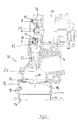
- Figs.1 and 2 illustrate a preferred embodiment of a valve unit 10 according to the present invention. It comprises a valve body 12 with an internal passage 13 having an inlet 14 and an outlet 16.
- the internal passage 13 can be closed by means of a disk-shaped closing member 18 that is fixedly attached at one end of an actuating shaft 20.
- the actuating shaft 20 is slideable in a bushing 22 mounted in a wall of the internal passage 13. Actuation of the actuating shaft 20 allows moving the closing member 18 between a closed position, preferably on a seat 24 in the internal passage, and an open position off the valve seat 24. In Fig.1, moving the actuating shaft 20 downwards permits to lift the closing member 18 off the valve seat 24, thereby opening the internal passage 13.
- the closing member 18 preferably has a peripheral sealing surface that, in the closed position, rests on an annular sealing surface on the valve seat 24.
- Actuation of the valve shaft 20 is carried out by means of a converting mechanism that converts the rotational movement of a rotatable drive shaft 28 into a linear movement.
- the drive shaft 28 preferably is a shaft mounted to the rotor of an electric motor 30.
- the converting mechanism comprises a driving member 32, an actuating member 34 and a supporting member 36.
- the driving member 32 has one end connected at joint A to the drive shaft 28 so as to drive it in rotation and is further connected to the actuating member 34 by a revolute joint B.
- the actuating member 34 is also connected to the supporting member 36 by a revolute joint C.
- the supporting member 36 is pivotally mounted onto the valve body by a fixed revolute joint D, forming a grounded pivot connection.
- the actuating member comprises a fu r-ther joint E, which permits to transmit an axial actuating force to the actuating shaft 20.
- the positions of the joints A, B, C, D and E are selected in such a way that, for the operating angle range of the drive shaft 28, joint E remains substantially aligned with the actuating shaft axis 38. This also means that joint E remains substantially aligned with the actuating shaft over the desired opening stroke of the actuating shaft.
- Figs.3 and 4 The principle of the converting mechanism is schematically represented in Figs.3 and 4. Referring first to Fig.3, the actuating member 34, driving member 32 and supporting member 36 with joints A through D form a four link mechanism. In the present mechanism, the actuating force employed to actuate the valve shaft 20 is taken up from this four bar mechanism about a given point P (Fig.3), by means of joint E.
- Fig.4 the trajectories of the different members of the mechanism are represented.
- joint E or point P
- joint A follows a circular trajectory as the driving member 32 is rotated by the drive shaft 28 at joint A.
- the angular rotation of the drive shaft 28 at joint A determines the vertical displacement of point P, this vertical displacement being used to transmit an axial actuating force to the actuating shaft 20 by joint E.
- the angular displacement of the drive shaft 28 determines the stroke of the actuating shaft 20.
- joint E follows a circular trajectory as the drive shaft 28 is actuated to move the closing member 18, and joint E will undergo both axial and transversal (horizontal) displacements.
- the radius of curvature of the trajectory of joint E is large enough, so that the transversal displacement of joint E is small.
- joint E can be considered to remain essentially aligned with the axis of the actuati ng shaft.
- the present converting mechanism transmits an essentially axial force to the actuating shaft 20.
- Fig.4 The converting mechanism in Fig.4 is shown in the configuration corresponding to the closed valve (closing member resting on valve seat). Clockwise actuation of the drive shaft 28 (at joint A) causes a downward displacement of joint E, which follows a circular path indicated 40 in Fig.4. At joint E (coinciding with point P of Fig.3), a downward axial actuating force is transmitted to the actuating shaft, so that the closing member 18 is lifted off the valve seat, thereby opening the valve passage. Further clockwise rotation of the drive shaft 28 causes the closing member 18 to move further away from its seat 24.
- the drive shaft 28 is rotated in the counter-clockwise direction so as to create an upward actuating force at joint E, until the closing member 18 is back onto the valve seat 24.
- the actuating shaft 20 has an operating stroke between the closed position and the maximal open position, that is determined by the operating angle range of the drive shaft 28.
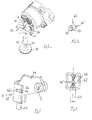
- connection sign 42 indicates a coupling element associated with the actuating shaft 20.
- This coupling element 42 is preferably a vertically arranged U-shaped metal piece.
- the spacing between the parallel side portions 46 is sufficient for inserting therein the actuating shaft, which is fixedly attached (e.g. by welding) to the coupling element 42, as well as the bottom left corner (corresponding to the symbolic point P of Fig.3) of the actuating member 34.
- the side portions 46 are each provided with a transversal guide slot 48.
- the transversal guide slots 48 are arranged at the same height, and advantageously define flat bearing surfaces. The bottom left corner (in Figs.
- the actuating member 34 has a cylindrical bore 50, in which a coupling pin 52 is arranged.
- the coupling pin 52 in fact has a central cylindrical portion 53 with a diameter matching that of bore 50, and has two opposite end portions 54 and 54' that each engage with a respective guide slot 48 on the coupling element 42.
- the end portions 54 and 54' of the coupling pin 52 have a rectangular cross-section, so that they bear with flat sides on the guide slots 48 and can slide thereon.
- This structure of joint E allows some horizontal displacement to the coupling pin 52, which is due to the circular trajectory of the coupling pin.
- the actuating force is transmitted from the actuating member 34 to the actuating shaft by the coupling element. Since the coupling element is rotatable in the actuating member and the guide slots 48 are transversal to the actuating shaft 20, the axial actuating force is always transmitted by surface contact (between flat part of pin 52 and guide slots 48) whether the drive shaft is rotated clockwise or counter-clockwise. Hence there is no line contact, so that Hertz contact problems can be avoided.
- Driving member 32 preferably is a simple bar with one bore at its both ends. At joint A, driving member 32 has a bore of a diameter matching that of the drive shaft 32, to which it is fixedly connected, e.g. by welding or brazing.
- Actuating member 34 has a triangular shape, each corner of the actuating member 34 being involved in a connection, namely B, C and E. Revolute joints B and C are simply formed by a pivot coupling the driving member 32 with the actuating member 34, respectively the actuating member 34 with the supporting member 36.
- the supporting member 36 is formed as a fork-like member, both arms of the fork being joined at joint D, and extending on both sides of the actuating member to reach joint C.
- FIG.8 another construction for joint E is shown.
- the coupling element 42 of Fig.6 is replaced in Fig.8 by a pair of coupling frames 42' (only one shown) attached to the actuating shaft 20, on both sides of the actuating member 34.
- the coupling pin 50' may simply be of cylindrical shape and engaged in the bore (at point P) in the actuating member 34.
- Reference sign 56 indicates two rubber elements of high stiffness that link each end of the coupling pin 52' to the frame 42'.
- the rubber elements 56 may be attached to the frame 42' and coupling pin 52' by conventional vulcanisation.
- the rubber elements 56 extend from the upper part, respectively lower part, of the frame 42' to the coupling pin 52', in such a way that the remainder of the frame-inside is free of rubber.
- This structure provides, due to the rubber stiffness, a relatively important resistance to movements of the actuating pin 52' in axial directions (in order to transmit the actuating force), but however allows the coupling pin to move transversally (thereby absorbing the transversal components of the actuating force).
Applications Claiming Priority (2)
| Application Number | Priority Date | Filing Date | Title |
|---|---|---|---|
| GBGB0302020.3A GB0302020D0 (en) | 2003-01-29 | 2003-01-29 | EGR valve |
| GB0302020 | 2003-01-29 |
Publications (2)
| Publication Number | Publication Date |
|---|---|
| EP1443203A2 true EP1443203A2 (de) | 2004-08-04 |
| EP1443203A3 EP1443203A3 (de) | 2007-09-05 |
Family
ID=9952017
Family Applications (1)
| Application Number | Title | Priority Date | Filing Date |
|---|---|---|---|
| EP03103209A Withdrawn EP1443203A3 (de) | 2003-01-29 | 2003-08-21 | Klappeneinheit |
Country Status (2)
| Country | Link |
|---|---|
| EP (1) | EP1443203A3 (de) |
| GB (1) | GB0302020D0 (de) |
Cited By (1)
| Publication number | Priority date | Publication date | Assignee | Title |
|---|---|---|---|---|
| KR102196742B1 (ko) * | 2019-10-07 | 2020-12-30 | 캄텍주식회사 | 차량용 egr 밸브 |
Citations (4)
| Publication number | Priority date | Publication date | Assignee | Title |
|---|---|---|---|---|
| US4213377A (en) * | 1978-12-18 | 1980-07-22 | Hedger John H | Reciprocating engine with improved power output means |
| EP0533546A1 (de) * | 1991-09-16 | 1993-03-24 | Labinal | Verbesserungen an Abgasrückführeinrichtungen |
| EP1028249A2 (de) * | 1999-02-12 | 2000-08-16 | Eaton Corporation | Abgasrückführungssystem und Betätigungsvorrichtung dafür |
| WO2001083975A1 (en) * | 2000-05-03 | 2001-11-08 | Cooperstandard Automotive Fluid Systems | Egr valve apparatus |
-
2003
- 2003-01-29 GB GBGB0302020.3A patent/GB0302020D0/en not_active Ceased
- 2003-08-21 EP EP03103209A patent/EP1443203A3/de not_active Withdrawn
Patent Citations (4)
| Publication number | Priority date | Publication date | Assignee | Title |
|---|---|---|---|---|
| US4213377A (en) * | 1978-12-18 | 1980-07-22 | Hedger John H | Reciprocating engine with improved power output means |
| EP0533546A1 (de) * | 1991-09-16 | 1993-03-24 | Labinal | Verbesserungen an Abgasrückführeinrichtungen |
| EP1028249A2 (de) * | 1999-02-12 | 2000-08-16 | Eaton Corporation | Abgasrückführungssystem und Betätigungsvorrichtung dafür |
| WO2001083975A1 (en) * | 2000-05-03 | 2001-11-08 | Cooperstandard Automotive Fluid Systems | Egr valve apparatus |
Cited By (1)
| Publication number | Priority date | Publication date | Assignee | Title |
|---|---|---|---|---|
| KR102196742B1 (ko) * | 2019-10-07 | 2020-12-30 | 캄텍주식회사 | 차량용 egr 밸브 |
Also Published As
| Publication number | Publication date |
|---|---|
| GB0302020D0 (en) | 2003-02-26 |
| EP1443203A3 (de) | 2007-09-05 |
Similar Documents
| Publication | Publication Date | Title |
|---|---|---|
| US7708254B2 (en) | Actuator apparatus for operating and locking a control valve and a method for its use | |
| JP4689752B2 (ja) | 駆動機構の改善された方形真空ゲートバルブ | |
| EP2600042B1 (de) | Vorrichtung zur Vorspannung von Ventilverschlusselementen | |
| JPH0742850A (ja) | ロータリーディスク弁 | |
| US4666124A (en) | Valve operator for a plug-type valve | |
| CN100424323C (zh) | 电磁驱动阀 | |
| JP2007040238A5 (de) | ||
| KR101816771B1 (ko) | 링크로드 세그먼트형 무(無)시트 볼밸브 | |
| US9562612B2 (en) | Pressure control valve assembly | |
| JPH0842748A (ja) | 真空バルブのためのバルブ装置 | |
| US20020011578A1 (en) | Pneumatic actuator | |
| CN100359153C (zh) | 废气再循环阀 | |
| JP2007002670A (ja) | アクチュエータ装置 | |
| EP1443203A2 (de) | Klappeneinheit | |
| KR20010030312A (ko) | 게이트 밸브 장치 | |
| US6056262A (en) | Universal coupler for a self aligning linear actuator | |
| KR101655129B1 (ko) | 배기가스 재순환밸브 | |
| JPH0642672A (ja) | ロータリーバルブ用アクチュエーター | |
| JP5049661B2 (ja) | ダイヤフラム弁のリミットスイッチ作動機構 | |
| KR20200130462A (ko) | 선박용 유체 제어 밸브 장치 | |
| KR200288029Y1 (ko) | 수동겸용 전동 글로브밸브장치 | |
| KR102550352B1 (ko) | 다축모션 구조의 버터플라이 댐퍼 | |
| CA2610218C (en) | Manual valve operator | |
| US7048513B2 (en) | Gas pressure driven fluid pump having compression spring pivot mechanism and damping system | |
| KR102381706B1 (ko) | 정밀 유량제어가 가능한 이지알 밸브조립체 |
Legal Events
| Date | Code | Title | Description |
|---|---|---|---|
| PUAI | Public reference made under article 153(3) epc to a published international application that has entered the european phase |
Free format text: ORIGINAL CODE: 0009012 |
|
| AK | Designated contracting states |
Kind code of ref document: A2 Designated state(s): AT BE BG CH CY CZ DE DK EE ES FI FR GB GR HU IE IT LI LU MC NL PT RO SE SI SK TR |
|
| AX | Request for extension of the european patent |
Extension state: AL LT LV MK |
|
| PUAL | Search report despatched |
Free format text: ORIGINAL CODE: 0009013 |
|
| AK | Designated contracting states |
Kind code of ref document: A3 Designated state(s): AT BE BG CH CY CZ DE DK EE ES FI FR GB GR HU IE IT LI LU MC NL PT RO SE SI SK TR |
|
| AX | Request for extension of the european patent |
Extension state: AL LT LV MK |
|
| 17P | Request for examination filed |
Effective date: 20071012 |
|
| 17Q | First examination report despatched |
Effective date: 20071115 |
|
| AKX | Designation fees paid |
Designated state(s): AT BE BG CH CY CZ DE DK EE ES FI FR GB GR HU IE IT LI LU MC NL PT RO SE SI SK TR |
|
| STAA | Information on the status of an ep patent application or granted ep patent |
Free format text: STATUS: THE APPLICATION IS DEEMED TO BE WITHDRAWN |
|
| 18D | Application deemed to be withdrawn |
Effective date: 20080326 |