EP1442861A2 - Schneidblatt mit Geräuschdämpfungsbohrung - Google Patents
Schneidblatt mit Geräuschdämpfungsbohrung Download PDFInfo
- Publication number
- EP1442861A2 EP1442861A2 EP04100375A EP04100375A EP1442861A2 EP 1442861 A2 EP1442861 A2 EP 1442861A2 EP 04100375 A EP04100375 A EP 04100375A EP 04100375 A EP04100375 A EP 04100375A EP 1442861 A2 EP1442861 A2 EP 1442861A2
- Authority
- EP
- European Patent Office
- Prior art keywords
- cutting blade
- bores
- cutting
- blade according
- holes
- Prior art date
- Legal status (The legal status is an assumption and is not a legal conclusion. Google has not performed a legal analysis and makes no representation as to the accuracy of the status listed.)
- Granted
Links
Images

Classifications
-
- B—PERFORMING OPERATIONS; TRANSPORTING
- B23—MACHINE TOOLS; METAL-WORKING NOT OTHERWISE PROVIDED FOR
- B23D—PLANING; SLOTTING; SHEARING; BROACHING; SAWING; FILING; SCRAPING; LIKE OPERATIONS FOR WORKING METAL BY REMOVING MATERIAL, NOT OTHERWISE PROVIDED FOR
- B23D61/00—Tools for sawing machines or sawing devices; Clamping devices for these tools
- B23D61/02—Circular saw blades
- B23D61/025—Details of saw blade body
- B23D61/0275—Slots in the saw blade body for reducing tension or vibration
-
- B—PERFORMING OPERATIONS; TRANSPORTING
- B24—GRINDING; POLISHING
- B24D—TOOLS FOR GRINDING, BUFFING OR SHARPENING
- B24D5/00—Bonded abrasive wheels, or wheels with inserted abrasive blocks, designed for acting only by their periphery; Bushings or mountings therefor
- B24D5/12—Cut-off wheels
- B24D5/123—Cut-off wheels having different cutting segments
Definitions
- the invention relates to a disk-shaped cutting blade, in particular for hand-held Cutting devices, with several cutting segments arranged on the circumference of the cutting blade, a center hole for attaching the cutting blade to a power-operated Tool and a center hole that has a variety of holes and between the center hole and the cutting segments is arranged.
- Such cutting blades are used, for example, in angle grinders or saws.
- the cutting blades are often designed as diamond cutting discs and in Dry cutting process applied. In such applications, it usually happens a strong noise pollution for the user, which can reach up to about 120 dB (A). On Many known cutting blades are therefore made through openings, one Should cause noise reduction.
- EP 1 099 524 describes a diamond cutting disc, both for better heat dissipation as well as to minimize noise has a variety of holes that are arranged on several spiral lines.
- the large number of breakthroughs a certain transparency of the cutting disc during operation, which is greater for the operator Should provide control options.
- the present invention has for its object, the aforementioned in a cutting blade Avoid disadvantages and achieve greater noise reduction.
- the object is achieved in that all holes in the center hole are arranged in at least two hole groups and all holes one each Bore group arranged on the nodes of a spirally curved grid are.
- areas can be formed between the groups, which are not weakened by bores and thus for sufficient rigidity of the Can provide cutting blade in operation.
- the cutting blade has multiple rotational symmetry and the number of groups of holes with the number of rotational symmetry matches. Due to the rotational symmetry, the effect of the sound absorbing effect Interference will be amplified.
- the grid preferably has at least three spiral sections, which are formed by straight axis sections get cut. By arranging the holes on straight sections of the axis the manufacturing outlay of the hole grid can be reduced.
- the grid by the spiral sections and the axis sections grid fields formed.
- the area of the lattice fields takes one another both in the direction of the spiral sections as well as in the direction of the straight axis sections with increasing proximity to Center hole and thus the density of the holes too. Through this to the center hole towards an increasingly dense arrangement of the holes can be a particularly large noise reduction be achieved.
- the distances between adjacent bores on the axle sections are the same. This simplifies the manufacture of the cutting blade. It is favorable that the groups of holes are at a minimum distance from one another that is at least twice as large as the largest distances between adjacent holes on the axis sections. In this way, relatively wide, non-weakened areas are obtained between the groups of holes, which ensures sufficient rigidity of the cutting blade during operation.
- the diameter of the bores increases the spiral sections radially from the outside inwards in one step or in several steps. As a result, the overlap that occurs during operation between the bores becomes one Spiral section enlarged, both to reduce noise and to improve Heat dissipation leads.
- the bores advantageously have a diameter that is between 4.5 and 6.5 mm lies. With these bore diameters, the special arrangement of the bores maintain a good stiffness of the cutting blade despite significant noise reduction become.
- the center hole radially a minimum distance of one third of the Has radius of the cutting blade to an axis of rotation of the cutting blade, whereby the Stability of the cutting blade can be increased further.
- the cutting segments are undercuts formed on the outer circumference of the cutting blade. It is between each two adjacent undercuts formed an intermediate hole, the intermediate holes have different distances from each other. This can defective tensions that lead to a shorter service life of the cutting segments, be avoided. At the same time, the intermediate holes for damping the Vibration excitation on the circumference of the cutting blade cause an additional Reduction of the noise level helps.
- the above-mentioned object is achieved in an alternative embodiment solved in that the cutting segments by undercuts on the outer circumference of the cutting blade are formed and between two adjacent undercuts an intermediate bore is formed, the intermediate bores with one another have different distances. Damping can only be achieved through the intermediate holes of excitation vibrations can be achieved in operation, resulting in less noise has the consequence. Due to the at least sectionally irregular arrangement of the Intermediate bores can reduce noise through noise-reducing interference can still be improved.
- the intermediate bores have rotational symmetry.
- the noise-damping interference can be amplified by the rotational symmetry.
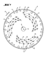
- a disc-shaped cutting blade 2 is shown, the several on its circumference Has cutting segments 4. Each of the cutting segments 4 is in the circumferential direction limited by two adjacent undercuts 5.
- the cutting blade 2 is used, for example, to cut and cut hard materials such as Stone, concrete, metal, etc.
- the cutting blade 2 can be used, for example, as a diamond cutting disc be designed for use in the dry cutting process.
- the cutting segments can be filled with abrasive diamond grains, for example.
- a center hole 6 is formed, through which the Cutting blade 2 can be connected to a power tool that the Cutting blade 2 can rotate in operation in a direction of rotation 8 about an axis of rotation 10.
- the holes 14 of each of the three hole groups 12 are one at the nodes imaginary grid 16 shown in broken lines, which consists of three spiral sections 18 composed, cut by six straight axis sections 20 each become.
- the spiral sections 18 are arranged so that each of the three grids 16 bends in the direction of rotation of 8 towards the center bore 6.
- the acute angle takes between the axis sections 20 and the respective radius that passes through the intersection of the respective axis section 20 goes with the circumference of the cutting blade 2, from the Axis sections 20 with the holes 14 that are outer relative to the center hole 6 from the axle sections 20 with the inner bores 14, i.e.
- the angles between the Axis sections 20 and the associated radius of a grid 16 are in the direction the spiral sections 18 pointed towards the center hole.
- the radially innermost Holes 14 of each group of holes 12 with respect to the center hole 6 one Distance of just over a third of the radius of the cutting blade 2.
- the bores 14 of a grid 16 are designed such that the two distances between the adjacent bores 14 of the three bores 14 on an axis section 20 are the same.
- the distances between adjacent holes increase 14 on all spiral sections 18 in the direction of rotation, that is, with increasing approach to the Center hole 6, from. In this way, the holes in the direction of the Center bore 6 increasingly.
- the holes 14 in the center hole all have a diameter in a size range from 4.5 to 6.5 mm. In the embodiment shown in FIG. 1, all have Holes of the same diameter. However, it is also possible that the diameter the bores 14 of a spiral section 18 in the direction of rotation 8 one or more times or is also enlarged between all holes 14, as shown in Fig. 2.
- an intermediate bore 22 is formed in each case. All intermediate bores 22 have the same radial distance from the center bore 6 on. With each other, i.e. In contrast, the distances vary in the direction of rotation 8.
- the cutting blade 2 shown has a total of three-fold rotational symmetry, i.e. when the cutting blade 2 is rotated relative to an image, it comes with this every 120 ° recurring to overlap.
- both the holes 14 of the center hole and The intermediate bores 22 in the area of the cutting segments 4 can also be clearly identified Noise reduction when operating a hand-held cutting device, e.g. a diamond cutting disc can be achieved in the dry cutting process.
- the intermediate bores 22 for a damping of the vibrational excitation on the circumference that occurs as soon as the cutting segments 4 penetrate a workpiece to be machined. on the other hand is due to the multiple rotational symmetry, both of the intermediate bores 22 and the hole groups 12 of the center hole, and further by the special grid-shaped arrangement of the individual groups of holes partially a damping interference of the generated Sound waves achieved, which leads to a significant reduction in the resulting in operation Noise level leads.
- the cutting blade 2 shown by the special arrangement of the center holes improved cooling, optimized Cutting material removal and weight reduction achieved.
Landscapes
- Engineering & Computer Science (AREA)
- Mechanical Engineering (AREA)
- Polishing Bodies And Polishing Tools (AREA)
- Processing Of Stones Or Stones Resemblance Materials (AREA)
Abstract
Description
Günstig ist, dass die Bohrungsgruppen untereinander einen Mindestabstand aufweisen, der mindestens doppelt so gross ist wie die grössten Abstände benachbarter Bohrungen auf den Achsabschnitten. Auf diese Weise erhält man zwischen den Bohrungsgruppen relativ breite ungeschwächte Bereiche, wodurch eine ausreichende Steifigkeit des Schneidblattes im Betrieb sichergestellt wird.
- Fig. 1
- eine Ansicht eines erfindungsgemässen Schneidblattes mit strichpunktiert dargestelltem imaginären Gitter und
- Fig. 2
- eine Ansicht eines erfindungsgemässen Schneidblattes mit unterschiedlichen Bohrungsdurchmessern der Mittelbohrung.
Claims (14)
- Schneidblatt, insbesondere für handgeführte Trenngeräte, mit mehreren an einem Aussenumfang des Schneidblatts angeordneten Schneidsegmenten, einer Zentrumsbohrung zur Befestigung des Schneidblattes an einem kraftbetriebenen Arbeitsgerät und einer Mittellochung, die eine Vielzahl von Bohrungen aufweist, die zwischen der Zentrumsbohrung und den Schneidsegmenten angeordnet ist, dadurch gekennzeichnet, dass die Bohrungen (14) der Mittellochung in mindestens zwei Bohrungsgruppen (12) angeordnet sind und die Bohrungen (14) jeweils einer Bohrungsgruppe (12) die Knotenpunkte eines spiralförmig gekrümmten Gitters (16) bilden.
- Schneidblatt nach Anspruch 1, dadurch gekennzeichnet, dass das Schneidblatt (2) eine mehrzählige Rotationssymmetrie aufweist und die Anzahl der Bohrungsgruppen (12) mit der Symmetriezähligkeit übereinstimmt.
- Schneidblatt nach Anspruch 1 oder 2, dadurch gekennzeichnet, dass sich das Gitter (16) in Drehrichtung (8) des Schneidblattes (2) der Zentrumsbohrung (6) annähert.
- Schneidblatt nach einem der Ansprüche 1 bis 3, dadurch gekennzeichnet, dass das Gitter (16) mindestens zwei Spiralabschnitte (18) aufweist, die durch gerade Achsabschnitte (20) geschnitten werden.
- Schneidblatt nach einem der Ansprüche 1 bis 4, dadurch gekennzeichnet, dass das Gitter (16) Gitterfelder ausbildet, deren Flächen untereinander sowohl in Richtung der Spiralabschnitte (18) als auch in Richtung der geraden Achsabschnitte (20) mit zunehmender Nähe zur Zentrumsbohrung (6) abnehmen.
- Schneidblatt nach Anspruch 4 oder 5, dadurch gekennzeichnet, dass die Abstände zwischen benachbarten Bohrungen (14) desselben Spiralabschnittes (18) mit zunehmender Nähe zur Zentrumsbohrung (6) abnehmen.
- Schneidblatt nach einem der Ansprüche 4 bis 6, dadurch gekennzeichnet, dass die Abstände zwischen benachbarten Bohrungen (14) desselben Achsabschnittes (20) gleich sind.
- Schneidblatt nach einem der Ansprüche 4 bis 7, dadurch gekennzeichnet, dass die Bohrungsgruppen (12) untereinander einen Mindestabstand aufweisen, der mindestens doppelt so gross ist wie die grössten Abstände benachbarter Bohrungen (14) auf den Achsabschnitten (20).
- Schneidblatt nach einem der Ansprüche 4 bis 8, dadurch gekennzeichnet, dass sich die Durchmesser der Bohrungen auf den Spiralabschnitten (18) gegenüber der Zentrumsbohrung von aussen nach innen in einem Schritt oder in mehreren Schritten vergrössern.
- Schneidblatt nach einem der Ansprüche 1 bis 9, dadurch gekennzeichnet, dass die Bohrungen (14) einen Durchmesser aufweisen, der zwischen 4,5 und 6,5 mm liegt.
- Schneidblatt nach einem der Ansprüche 1 bis 10, dadurch gekennzeichnet, dass die Mittellochung radial einen Mindestabstand von einem Drittel des Radius des Schneidblattes (2) zu einer Drehachse (10) des Schneidblattes (2) aufweist.
- Schneidblatt nach einem der Ansprüche 1 bis 11, dadurch gekennzeichnet, dass die Schneidsegmente (4) durch Hinterschneidungen (5) am Aussenumfang des Schneidblattes (2) ausgebildet sind und zwischen jeweils zwei benachbarten Hinterschneidungen (5) eine Zwischenbohrung (22) ausgebildet ist, wobei die Zwischenbohrungen (22) untereinander unterschiedliche Abstände aufweisen.
- Schneidblatt nach dem Oberbegriff des Anspruchs 1, dadurch gekennzeichnet, dass die Schneidsegmente (4) durch Hinterschneidungen (5) am Aussenumfang des Schneidblattes (2) ausgebildet sind und zwischen jeweils zwei benachbarten Hinterschneidungen (5) eine Zwischenbohrung (22) ausgebildet ist, wobei die Zwischenbohrungen (22) untereinander unterschiedliche Abstände aufweisen.
- Schneidblatt nach Anspruch 13, dadurch gekennzeichnet, dass die Zwischenbohrungen (22) eine Rotationssymmetrie aufweisen.
Applications Claiming Priority (2)
| Application Number | Priority Date | Filing Date | Title |
|---|---|---|---|
| DE10304162A DE10304162B3 (de) | 2003-02-03 | 2003-02-03 | Schneidblatt mit einer Geräuschdämpfungseinrichtung, insbesondere für handgeführte Trenngeräte |
| DE10304162 | 2003-02-03 |
Publications (3)
| Publication Number | Publication Date |
|---|---|
| EP1442861A2 true EP1442861A2 (de) | 2004-08-04 |
| EP1442861A3 EP1442861A3 (de) | 2004-08-18 |
| EP1442861B1 EP1442861B1 (de) | 2007-12-05 |
Family
ID=32240588
Family Applications (1)
| Application Number | Title | Priority Date | Filing Date |
|---|---|---|---|
| EP04100375A Expired - Lifetime EP1442861B1 (de) | 2003-02-03 | 2004-02-03 | Schneidblatt mit Geräuschdämpfungsbohrung |
Country Status (2)
| Country | Link |
|---|---|
| EP (1) | EP1442861B1 (de) |
| DE (2) | DE10304162B3 (de) |
Cited By (1)
| Publication number | Priority date | Publication date | Assignee | Title |
|---|---|---|---|---|
| WO2005063429A1 (en) * | 2003-12-30 | 2005-07-14 | Aktiebolaget Electrolux | A saw blade for a handheld working tool |
Families Citing this family (2)
| Publication number | Priority date | Publication date | Assignee | Title |
|---|---|---|---|---|
| DE202007012295U1 (de) * | 2007-09-01 | 2007-12-27 | Edessö Werk - Ed. Engels & Söhne GmbH & Co. KG | Sägeblatt |
| DE102014103719A1 (de) * | 2014-03-19 | 2015-09-24 | Dr. Müller Diamantmetall AG | Schälschleifwerkzeug |
Family Cites Families (6)
| Publication number | Priority date | Publication date | Assignee | Title |
|---|---|---|---|---|
| DE8304110U1 (de) * | 1983-02-15 | 1983-06-23 | Gröschke, Dieter, 8472 Schwarzenfeld | Kreissägenblatt |
| US5802947A (en) * | 1996-10-15 | 1998-09-08 | Credo Tool Company | Dimpled circular saw blade |
| WO2000043179A1 (en) * | 1999-01-25 | 2000-07-27 | Black & Decker Inc. | Saw blade for cutting fiber cement |
| DE29910442U1 (de) * | 1999-06-15 | 2000-10-19 | DIEWE Diamantwerkzeuge GmbH, 86510 Ried | Trennscheibe |
| DE10033101A1 (de) * | 2000-07-07 | 2002-01-17 | Hilti Ag | Scheibenförmiges Trennwerkzeug |
| DE20203238U1 (de) * | 2002-03-01 | 2003-07-10 | DIEWE-Diamantwerkzeuge GmbH, 86510 Ried | Schleifwerkzeug, insbesondere Trennschleifwerkzeug |
-
2003
- 2003-02-03 DE DE10304162A patent/DE10304162B3/de not_active Expired - Fee Related
-
2004
- 2004-02-03 EP EP04100375A patent/EP1442861B1/de not_active Expired - Lifetime
- 2004-02-03 DE DE502004005629T patent/DE502004005629D1/de not_active Expired - Lifetime
Cited By (1)
| Publication number | Priority date | Publication date | Assignee | Title |
|---|---|---|---|---|
| WO2005063429A1 (en) * | 2003-12-30 | 2005-07-14 | Aktiebolaget Electrolux | A saw blade for a handheld working tool |
Also Published As
| Publication number | Publication date |
|---|---|
| EP1442861B1 (de) | 2007-12-05 |
| DE10304162B3 (de) | 2004-06-03 |
| EP1442861A3 (de) | 2004-08-18 |
| DE502004005629D1 (de) | 2008-01-17 |
Similar Documents
| Publication | Publication Date | Title |
|---|---|---|
| DE60128425T2 (de) | Schneidrad zum Einkerben von spröden Materialien | |
| DE69922231T2 (de) | Diamantiertes blatt mit schneidsegmenten zur verwendung in schneid-, schleif- oder bohrvorrichtungen | |
| DE602004000740T2 (de) | Herstellung von Nuten | |
| DE69217920T2 (de) | Bohrmeissel mit verbessertem schneideinsatzmuster | |
| DE102007050050A1 (de) | Rundlaufwerkzeug, insbesondere Bohrer | |
| DE69425364T2 (de) | Vorrichtung zur Erleichterung des Schneidens | |
| DE2945766A1 (de) | Bohrkrone mit hexagonalem hauptabschnitt | |
| EP0239676B1 (de) | Sägeblatt | |
| EP1170107A1 (de) | Scheibenförmiges Trennwerkzeug | |
| EP1991394B1 (de) | Schleiflamelle und diese enthaltende schleifscheibe | |
| EP3681675B1 (de) | Schleifartikel | |
| EP3266627B1 (de) | Fahrzeugluftreifen | |
| EP1977858A1 (de) | Schleifsystem | |
| EP1142673B1 (de) | Schleiflamelle und Schleifteller mit einer Mehrzahl von solchen | |
| WO2016166200A1 (de) | Sägewerkzeug mit mehreren diamantsägeblättern zum ausbilden einer oberflächenstruktur auf einer fahrbahnoberfläche | |
| EP1867420B1 (de) | Sägeblatt mit Seitenschlag | |
| EP1442861B1 (de) | Schneidblatt mit Geräuschdämpfungsbohrung | |
| DE4243480A1 (de) | Trockensägeblatt | |
| DE102006011663A1 (de) | Angetriebenes Werkzeug mit Staubsammelfunktion | |
| EP2632638A1 (de) | Schleiflamelle zum anordnen auf einer um eine drehachse rotierend antreibbaren schleifscheibe | |
| DE4414219C2 (de) | Rotor für eine elektrische Maschine | |
| EP2227938B1 (de) | Messerkopf eines handgeführten Arbeitsgerätes | |
| EP1951476A1 (de) | Trennscheibe | |
| DE19822742A1 (de) | Kreisscheibenförmiges Werkzeug | |
| EP0043136B1 (de) | Segmentierte Trennscheibe |
Legal Events
| Date | Code | Title | Description |
|---|---|---|---|
| PUAI | Public reference made under article 153(3) epc to a published international application that has entered the european phase |
Free format text: ORIGINAL CODE: 0009012 |
|
| PUAL | Search report despatched |
Free format text: ORIGINAL CODE: 0009013 |
|
| AK | Designated contracting states |
Kind code of ref document: A2 Designated state(s): AT BE BG CH CY CZ DE DK EE ES FI FR GB GR HU IE IT LI LU MC NL PT RO SE SI SK TR |
|
| AX | Request for extension of the european patent |
Extension state: AL LT LV MK |
|
| AK | Designated contracting states |
Kind code of ref document: A3 Designated state(s): AT BE BG CH CY CZ DE DK EE ES FI FR GB GR HU IE IT LI LU MC NL PT RO SE SI SK TR |
|
| AX | Request for extension of the european patent |
Extension state: AL LT LV MK |
|
| 17P | Request for examination filed |
Effective date: 20050218 |
|
| AKX | Designation fees paid |
Designated state(s): BE CH DE FR LI |
|
| RBV | Designated contracting states (corrected) |
Designated state(s): BE CH DE FR LI |
|
| 17Q | First examination report despatched |
Effective date: 20051117 |
|
| GRAP | Despatch of communication of intention to grant a patent |
Free format text: ORIGINAL CODE: EPIDOSNIGR1 |
|
| GRAS | Grant fee paid |
Free format text: ORIGINAL CODE: EPIDOSNIGR3 |
|
| GRAA | (expected) grant |
Free format text: ORIGINAL CODE: 0009210 |
|
| AK | Designated contracting states |
Kind code of ref document: B1 Designated state(s): BE CH DE FR LI |
|
| REG | Reference to a national code |
Ref country code: CH Ref legal event code: EP |
|
| REF | Corresponds to: |
Ref document number: 502004005629 Country of ref document: DE Date of ref document: 20080117 Kind code of ref document: P |
|
| ET | Fr: translation filed | ||
| PLBE | No opposition filed within time limit |
Free format text: ORIGINAL CODE: 0009261 |
|
| STAA | Information on the status of an ep patent application or granted ep patent |
Free format text: STATUS: NO OPPOSITION FILED WITHIN TIME LIMIT |
|
| 26N | No opposition filed |
Effective date: 20080908 |
|
| REG | Reference to a national code |
Ref country code: FR Ref legal event code: PLFP Year of fee payment: 13 |
|
| REG | Reference to a national code |
Ref country code: FR Ref legal event code: PLFP Year of fee payment: 14 |
|
| REG | Reference to a national code |
Ref country code: FR Ref legal event code: PLFP Year of fee payment: 15 |
|
| PGFP | Annual fee paid to national office [announced via postgrant information from national office to epo] |
Ref country code: FR Payment date: 20230220 Year of fee payment: 20 Ref country code: CH Payment date: 20230307 Year of fee payment: 20 |
|
| PGFP | Annual fee paid to national office [announced via postgrant information from national office to epo] |
Ref country code: DE Payment date: 20230216 Year of fee payment: 20 Ref country code: BE Payment date: 20230216 Year of fee payment: 20 |
|
| P01 | Opt-out of the competence of the unified patent court (upc) registered |
Effective date: 20230830 |
|
| REG | Reference to a national code |
Ref country code: DE Ref legal event code: R071 Ref document number: 502004005629 Country of ref document: DE |
|
| REG | Reference to a national code |
Ref country code: CH Ref legal event code: PL |
|
| REG | Reference to a national code |
Ref country code: BE Ref legal event code: MK Effective date: 20240203 |