EP1442276B1 - Druckmessaufnehmer mit trennmembran und temperaturkompensation - Google Patents
Druckmessaufnehmer mit trennmembran und temperaturkompensation Download PDFInfo
- Publication number
- EP1442276B1 EP1442276B1 EP02774709A EP02774709A EP1442276B1 EP 1442276 B1 EP1442276 B1 EP 1442276B1 EP 02774709 A EP02774709 A EP 02774709A EP 02774709 A EP02774709 A EP 02774709A EP 1442276 B1 EP1442276 B1 EP 1442276B1
- Authority
- EP
- European Patent Office
- Prior art keywords
- pressure
- partition
- membrane
- metering
- sensor
- Prior art date
- Legal status (The legal status is an assumption and is not a legal conclusion. Google has not performed a legal analysis and makes no representation as to the accuracy of the status listed.)
- Expired - Lifetime
Links
- 239000012528 membrane Substances 0.000 title claims abstract description 94
- 230000001419 dependent effect Effects 0.000 claims abstract description 11
- 238000004891 communication Methods 0.000 claims abstract description 7
- 230000005540 biological transmission Effects 0.000 claims description 14
- 238000012937 correction Methods 0.000 claims description 11
- 230000001939 inductive effect Effects 0.000 claims description 2
- 238000012886 linear function Methods 0.000 claims description 2
- 230000003287 optical effect Effects 0.000 claims description 2
- 238000005192 partition Methods 0.000 claims 18
- 238000002604 ultrasonography Methods 0.000 claims 1
- 239000012530 fluid Substances 0.000 abstract description 8
- 238000012546 transfer Methods 0.000 abstract description 8
- 238000011156 evaluation Methods 0.000 abstract description 3
- 238000000926 separation method Methods 0.000 description 55
- 238000005259 measurement Methods 0.000 description 18
- 230000006870 function Effects 0.000 description 8
- 238000000034 method Methods 0.000 description 6
- 239000012212 insulator Substances 0.000 description 5
- 238000009530 blood pressure measurement Methods 0.000 description 3
- 239000000463 material Substances 0.000 description 3
- 238000009529 body temperature measurement Methods 0.000 description 2
- 238000009826 distribution Methods 0.000 description 2
- 238000002592 echocardiography Methods 0.000 description 2
- 239000010720 hydraulic oil Substances 0.000 description 2
- 238000013459 approach Methods 0.000 description 1
- 150000001875 compounds Chemical class 0.000 description 1
- 230000008094 contradictory effect Effects 0.000 description 1
- 238000010586 diagram Methods 0.000 description 1
- 239000006185 dispersion Substances 0.000 description 1
- 230000001105 regulatory effect Effects 0.000 description 1
- 230000002123 temporal effect Effects 0.000 description 1
- 238000003466 welding Methods 0.000 description 1
Images



Classifications
-
- G—PHYSICS
- G01—MEASURING; TESTING
- G01L—MEASURING FORCE, STRESS, TORQUE, WORK, MECHANICAL POWER, MECHANICAL EFFICIENCY, OR FLUID PRESSURE
- G01L9/00—Measuring steady of quasi-steady pressure of fluid or fluent solid material by electric or magnetic pressure-sensitive elements; Transmitting or indicating the displacement of mechanical pressure-sensitive elements, used to measure the steady or quasi-steady pressure of a fluid or fluent solid material, by electric or magnetic means
- G01L9/0041—Transmitting or indicating the displacement of flexible diaphragms
- G01L9/0072—Transmitting or indicating the displacement of flexible diaphragms using variations in capacitance
-
- G—PHYSICS
- G01—MEASURING; TESTING
- G01L—MEASURING FORCE, STRESS, TORQUE, WORK, MECHANICAL POWER, MECHANICAL EFFICIENCY, OR FLUID PRESSURE
- G01L9/00—Measuring steady of quasi-steady pressure of fluid or fluent solid material by electric or magnetic pressure-sensitive elements; Transmitting or indicating the displacement of mechanical pressure-sensitive elements, used to measure the steady or quasi-steady pressure of a fluid or fluent solid material, by electric or magnetic means
- G01L9/12—Measuring steady of quasi-steady pressure of fluid or fluent solid material by electric or magnetic pressure-sensitive elements; Transmitting or indicating the displacement of mechanical pressure-sensitive elements, used to measure the steady or quasi-steady pressure of a fluid or fluent solid material, by electric or magnetic means by making use of variations in capacitance, i.e. electric circuits therefor
- G01L9/125—Measuring steady of quasi-steady pressure of fluid or fluent solid material by electric or magnetic pressure-sensitive elements; Transmitting or indicating the displacement of mechanical pressure-sensitive elements, used to measure the steady or quasi-steady pressure of a fluid or fluent solid material, by electric or magnetic means by making use of variations in capacitance, i.e. electric circuits therefor with temperature compensating means
Definitions
- the invention relates to Druckmeßaufsacrificing with a separation membrane. More particularly, the invention relates to Druckmeßaufsacrificing in which the influence Temperature-induced deflections of the separation membrane on the pressure measurement is compensated.
- a generic Druckmeßauf choir for detecting a pressure in a first medium comprises a pressure measuring cell for generating a pressure-dependent signal; a separation membrane which is fastened with its edge to a separating body, wherein the separating membrane is acted upon on its first, the separator body facing surface with the prevailing in the first medium pressure, and forms with its second the separator body facing surface and the separating body a pressure chamber, which is filled with a transfer medium, further wherein the pressure chamber has an opening through which the internal pressure in the pressure chamber p int is transmitted by means of the transfer medium via a pressure supply line to the pressure measuring cell.
- the deflection d of the separating membrane is accompanied by a measuring error ⁇ p, because the pressure measuring cell measures the internal pressure p int instead of the external pressure p ext actually of interest.
- Schleiferböck discloses in European patent application 0 764 839 A1 is a pressure or differential pressure measuring device, in which the of the pressure measuring cell measured pressure value p or the differential pressure value ⁇ p for each of Separation membranes is corrected by a value ⁇ p (.DELTA.T).
- ⁇ T is the integrated temperature profile of the transmission medium in the Pressure supply determined based on the electrical resistance of a wire, the is guided along the pressure supply line.
- This temperature value .DELTA.T is then one Assigned measurement error ⁇ p, with which the measured printing error is corrected. Schleiferbock's approach is useful in that it is inhomogeneous Temperature distributions detected, which often occur in practice.
- the Druckmeßaufsacrificing invention for detecting a pressure in a first medium comprises a pressure measuring cell, for generating a pressure-dependent signal; a separator; a separation membrane with her Edge is attached to the separating body, wherein the separating membrane on its first, the separating body facing away from the surface in the first medium prevailing pressure can be acted upon, and with their second, the Separator facing surface and the separator a pressure chamber forms, which is filled with a transfer medium, wherein the pressure chamber a Pressure chamber opening through which they with the pressure measuring cell in Flow compound is; a sensor for determining the position of Separation membrane; and an evaluation unit that the of the pressure measuring cell signal corrected by a measurement error ⁇ p, which depends on the position of the Separation membrane depends.
- the position of the separation membrane is a measure of its deflection. she will preferably based on the distance between a region of the separation membrane and the separating body or a fixed with respect to the separating body Reference point determined.
- the reference point may preferably be in the range of Membranbetts lie, which formed in an end face of the separator may be, and at which the separation membrane at a pressure outside the Can apply nominal range.
- a sensor for determining the distance between the separating body and the Separating membrane is preferably a capacitive sensor or a Ultrasonic sensor used.
- other distance sensors are in particular inductive, resistive and optical sensors suitable.
- the determined distance of the separation membrane assigns a measurement error ⁇ p.
- the separation membrane can be made of a different material as the separating body to which it is attached, the underschliedlichen Thermal expansion coefficients of the materials cause the characteristic of the Measurement error ⁇ p as a function of the membrane distance, a temperature dependence having.
- temperature-dependent characteristics may also be possible then occur when the separating membrane and the separating body of the same Material exist.
- the Druckmeßauf choirs invention additionally at least one Temperature sensor, which detects the temperature of a measuring point, it allows the temperature dependence of the characteristic in the determination of the Measurement error ⁇ p to take into account.
- the measuring point can, for example, in Separator in the vicinity of the separation membrane, on the separation membrane, or in the Be arranged volume of the pressure chamber. In the latter case, the temperature the transmission medium used to the temperature influence on the ⁇ p (d) characteristic.
- Fig. 1 shows a pressure transducer according to the present invention, in this case a Differenzdruckmeßetzsacrificing.
- the separator 10 of this Differenzdruckmeßetz choirs has on its front side two coplanar separating membranes 11, 12 to which a first external pressure p 1 and a second external pressure p 2 are acted upon.
- the first separation membrane 11 closes a first pressure chamber 13 in the separation body
- the second separation membrane 12 closes a second pressure chamber 14 in the separation body.
- the pressure chambers are each delimited by the separation membrane and a membrane bed formed in the end face of the separation body.
- the pressure chambers are filled with a transmission medium, preferably a hydraulic oil.
- a transmission medium preferably a hydraulic oil.
- each one also filled with the transfer medium first 15 and a second 16 pressure supply to a Differenzdruckmeßzelle extending over the pressure supply lines with the prevailing pressure in the first pressure chamber 13 and p 1int in the second Druckkhunt 14 prevailing pressure p 2int acted on each other counteracting.
- the preprocessor board 35 is connected via preprocessor line 36 to the motherboard, on which the measured value to be output is converted into a 4-20 mA signal, if necessary after further corrections, ie the supply current of the pressure transducer at the supply terminal 42 is changed to 4 as a function of the measuring signal. 20 mA regulated.
- the motherboard also has a so-called HART modem, which allows digital communication with the pressure transducer.
- a first ultrasonic transducer 31st angeordet whose pulsed ultrasonic signal is preferably substantially propagates perpendicular to the plane of the separation membrane 11.
- the ultrasonic transducer 31 receives at least two echoes, namely first an echo from the membrane bed and then an echo from the first separation membrane 11.
- the temporal Distance of the two echoes is a measure of the distance of the first separation membrane from the membrane bed.
- Behind the second pressure chamber 14 is corresponding arranged an ultrasonic transducer 32, by means of which the current position of the second separation membrane 12 is determined.
- Both ultrasonic transducers 31, 32 are controlled by a control circuit 30, and evaluated, preferably on the Pre-processor board 35 is arranged.
- the ultrasonic frequencies used are preferably between 1 and 50 MHz.
- Suitable ultrasonic transducers are i.a. available as Moldell V208-RM from Panametrics Inc. Waltham, Mass., USA.
- Piezo film elements can also be used, as they are u.a. from AMP, Inc., Valley Forge, Pa., USA are available.
- the temperature dependence of Propagation speed of the ultrasonic signal in the transmission fluid in the transit time method described above for determining the Separation diaphragm position to improve the accuracy are taken into account.
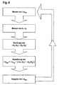
- the pre-processor board 35 From the pre-processor board 35 signals are transmitted to the motherboard, each representing the positions of the first separation membrane 11 and the second separation membrane 12. Based on the position signals for the two separation membranes, the measurement errors ⁇ p 1 (d 1 ) and ⁇ p 2 (d 2 ) are determined on the basis of the membrane positions d 1 and d 2 .
- either the respective correction value associated with a position signal is read from a table stored in a permanent memory element, or the correction value ⁇ p 1 or ⁇ p 2 is calculated on the basis of the respective position signal and coefficients stored in the memory element.
- FIG. 4 An inventive sequence for determining the actual external pressure difference is summarized in Fig. 4.
- Fig. 2 shows another embodiment of an inventive Differenzdruckmeßaufillons with a cylindrical body 100, the both end faces in each case has an integrated separating body 102, 104, in FIG in each case a membrane bed is formed. Over the two membrane beds is in each case a separating membrane 111, 112 attached pressure-tight manner, whereby between the both membrane bed and the associated separation membrane one each Pressure chamber 113, 114 is formed.
- the two pressure chambers 113, 114 each communicate via a channel with a central measuring cell chamber 120, which is separated by a measuring diaphragm 125 in two halves.
- the pressure chambers 113, 114 and the measuring cell chamber are filled with a transmission medium, in particular a hydraulic oil, via which the measuring diaphragm 125 counteracting the internal pressure of the two pressure chambers is acted upon.
- the Druckmeßauf choir further comprises two insulator inserts 101, 103, which preferably each form at least a portion of a membrane bed and a portion of a wall of the central measuring cell chamber 120.
- the two channels for establishing the flow connection between the two pressure chambers 113, 114 and the central measuring cell chamber 120 are preferably each formed in the two insulator inserts 101, 103.
- the first insulator insert 101 has on the portion of a first wall of the central measuring cell chamber 120, a first counter electrode 121 which is connected to a first counter electrode terminal 123, on the lateral surface of the base 100, and the second insulator insert 103 has on the portion of a second wall central measuring cell chamber 120, a second counter-electrode 122 which is connected to a second counter-electrode terminal 124 on the lateral surface of the base body 100.
- the measuring diaphragm 125 serves as a pressure-dependent variable measuring electrode to both counter electrodes.
- the determination of the separation membrane position is capacitive in this embodiment.
- an electrode 131, 132 which is insulated from the surroundings is provided in each of the two membrane beds, it being possible to arrange the electrodes in the insulator inserts 101, 103.
- the respective capacitance between the two electrodes 131, 132 and their surroundings is an indicator for the distance of the respective separating membrane 111, 112.
- the determination of the measuring errors ⁇ p 1 and ⁇ p 2 takes place on the basis of the two capacitances according to the procedure of FIG In connection with the first embodiment has been discussed in detail.
- the Differenz horrinßumformer two temperature sensors 133, 134., of which preferably one each in the two Trennkörpem 102, 104 are arranged in the vicinity of the respective membrane bed.
- a temperature dependence of the membrane characteristics can be taken into account when determining the measurement errors ⁇ p 1 and ⁇ p 2 .
- the filling pressure P is varied over a reasonable range of values in a suitable step size.
- the signal d * of a distance sensor - here the ultrasonic transducer 31 - is recorded, which represents the deflection d of the separation membrane.
- the signal value d is assigned a measurement error ⁇ p (d), which is determined, for example, by means of a temporarily connected relative pressure sensor 50. It is understood that the outside of the separation membrane and the reference side of the relative pressure sensor must be exposed to the same pressure.
- the characteristic thus determined is either stored in a memory form in a memory element, or the coefficient function, which reproduces the characteristic, are determined and stored in the memory element.
- the ⁇ p (d * ) associated with a d * is then read from the table, or the ⁇ p (d *) is calculated on the basis of d and the stored coefficients.
- a characteristic curve for different temperatures can be recorded, as indicated by the dashed line in FIG. 5.
- the separation membranes with sufficiently low dispersion of the characteristics can be produced and mounted on a membrane bed can, if necessary, to a individual determination of the characteristic curves on the fully assembled pressure transducer be waived.
- the separation membranes for example, on a Mounting ring preferably be pre-assembled by welding.
- the such pre-assembled modules of separation membrane and mounting ring are possibly simpler and more reproducible over a membrane bed mountable, so that a determination of the characteristic after assembly may not more is needed. Unless the variability of the characteristics between different modules is sufficiently small, can be based on an individual Determination of the characteristics may be omitted altogether. Otherwise, the Characteristic determination for the modules before assembly on Pressure transducer done.
Landscapes
- Physics & Mathematics (AREA)
- General Physics & Mathematics (AREA)
- Measuring Fluid Pressure (AREA)
Description
Wenngleich die Trennmembran eine möglichst geringe Steifigkeit aufweist, damit der interne Druck pint im Übertragungsmedium mit dem externen Druck pext im Prozeßmediumum möglichst gut übereinstimmt, ist der Einfluß der elastischen Eigenschaften der Trennmembran auf den internen Druck jedoch zumindest bei großen Auslenkungen der Trennmembran nicht mehr vernachlässigbar.
Der Druckmeßaufnehmer weist weiterhin zwei Isolatoreinsätze 101, 103 auf, welche vorzugsweise jeweils zumindest einen Teilabschnitt eines Membranbetts und einen Teilabschnitt einer Wand der zentralen Meßzellenkammer 120 bilden. Die beiden Kanäle zur Herstellung der Fließverbindung zwischen den beiden Druckkammem 113, 114 und der zentralen Meßzellenkammer 120 sind vorzugsweise jeweils in den beiden Isolatoreinsätzen 101, 103 ausgebildet.
Hierzu kann der oben beschriebene Vorgang bei verschiedenen Temperaturen durchgeführt werden. Die Kennlinien für verschiedene Temperaturen werden entweder tabellarisch im Speicherelement abgelegt werden, oder die ermittelte Temperturabhängigkeit der Kennlinie σp(d*) kann ggf. durch eine geeignete Funktion zweier Variablen beschrieben werden:
Claims (9)
- Druckmeßaufnehmer, umfassend
eine Druckmeßzelle (20), zur Erzeugung eines druckabhängigen Signals;
mindestens eine Trennmembran (11, 12), die mit ihrem Rand an einem Trennkörper (10) befestigt ist, wobei die Trennmembran (11, 12) auf ihrer ersten, dem Trennkörper (10) abgewandten Oberfläche mit dem in einem ersten Medium vorherrschenden Druck beaufschlagbar ist, und mit ihrer zweiten, dem Trennkörper (10) zugewandten Oberfläche und dem Trennkörper (10) eine Druckkammer (13, 14) bildet, die mit einem Übertragungsmedium befüllt ist, wobei die Druckkammer (13, 14) eine Öffnung aufweist, durch welche sie mit der Druckmeßzelle (20) in Fließverbindung steht;
mindestens einen Sensor (31, 32) zur Ermittlung der Position der Trennmembran (11, 12); und
eine Auswertungseinheit (40), welche den von der Druckmeßzelle (20) gemessenen Druckwert um einen Korrekturwert verändert, der von der Position der Trennmembran (11, 12) abhängt. - Druckmeßaufnehmer nach Anspruch 1, wobei der der Sensor ein kapazitiver Sensor ist, der den Abstand zwischen dem Trennkörper und der Trennmembran bestimmt.
- Druckaufnehmer nach Anspruch 1, wobei der Sensor ein induktiver Sensor ist.
- Druckaufnehmer nach Anspruch 1, wobei der Sensor ein Ultraschallsensor ist oder ein optischer Sensor ist.
- Druckaufnehmer nach einem der vorhergehenden Ansprüche, wobei der Korrekturwert zusätzlich von der Temperatur der Trennmembran und/oder des Trennkörpers abhängt.
- Druckaufnehmer nach einem der vorhergehenden Ansprüche, weiterhin umfassend ein Speicherelement, in welchem die Korrekturwerte in Abhängigkeit von der Position der Trennmembran tabellarisch gespeichert sind, und zur Veränderung des Druckmeßzellensignals von der Auswerteeinheit auslesbar sind.
- Druckaufnehmer nach Anspruch 6, wobei die Auswerteeinheit den Korrekturwert für Positionen, von denen kein Tabellenwert vorliegt durch Interpolation geeigneter Tabellenwerte ermittelt.
- Druckmeßaufnehmer nach einem der Ansprüche 1 -5, weiterhin umfassend ein Speicherelement, in welchem die Koeffizienten einer linearen Funktion oder einer Funktion höherer Ordnung gespeichert sind, um den Korrekturwert als Funktion der Position der Trennmembran zu berechnen.
- Druckmeßaufnehmer nach einem der vorhergehenden Ansprüche, wobei der Druckmeßaufnehmer ein Differenzdruckmeßaufnehmer zur Messung der Druckdifferenz zwischen dem Druck in dem ersten Medium und einem Druck in einem zweiten Medium ist, der zwei Trennmembranen, zwei Druckkkammern, und zwei Sensoren aufweist, wobei die erste Trennmembran mit dem ersten Druck und die zweite Trennmembran mit dem zweiten Druck beaufschlagbar ist.
Applications Claiming Priority (3)
| Application Number | Priority Date | Filing Date | Title |
|---|---|---|---|
| DE10150691 | 2001-10-17 | ||
| DE10150691A DE10150691A1 (de) | 2001-10-17 | 2001-10-17 | Druckmeßaufnehmer mit Trennmembran und Temperaturkompensation |
| PCT/EP2002/011442 WO2003034015A1 (de) | 2001-10-17 | 2002-10-12 | Druckmessaufnehmer mit trennmembran und temperaturkompensation |
Publications (2)
| Publication Number | Publication Date |
|---|---|
| EP1442276A1 EP1442276A1 (de) | 2004-08-04 |
| EP1442276B1 true EP1442276B1 (de) | 2005-12-28 |
Family
ID=7702469
Family Applications (1)
| Application Number | Title | Priority Date | Filing Date |
|---|---|---|---|
| EP02774709A Expired - Lifetime EP1442276B1 (de) | 2001-10-17 | 2002-10-12 | Druckmessaufnehmer mit trennmembran und temperaturkompensation |
Country Status (4)
| Country | Link |
|---|---|
| EP (1) | EP1442276B1 (de) |
| AT (1) | ATE314634T1 (de) |
| DE (2) | DE10150691A1 (de) |
| WO (1) | WO2003034015A1 (de) |
Cited By (1)
| Publication number | Priority date | Publication date | Assignee | Title |
|---|---|---|---|---|
| DE102021113265A1 (de) | 2021-05-21 | 2022-11-24 | Vega Grieshaber Kg | Drucksensor mit Kompensationseinheit und Verfahren zur Kompensation |
Families Citing this family (8)
| Publication number | Priority date | Publication date | Assignee | Title |
|---|---|---|---|---|
| DE10319417A1 (de) * | 2003-04-29 | 2004-11-18 | Endress + Hauser Gmbh + Co. Kg | Druckaufnehmer mit Temperaturkompensation |
| DE102004052950A1 (de) * | 2004-10-29 | 2006-05-04 | Endress + Hauser Gmbh + Co. Kg | Druckaufnehmer mit hydraulischer Druckübertragung |
| DE102004053884A1 (de) * | 2004-11-04 | 2006-05-24 | Endress + Hauser Gmbh + Co. Kg | Messwertaufnehmer mit Temperaturkompensation |
| DE102005035931B4 (de) * | 2005-07-28 | 2013-05-29 | Endress + Hauser Gmbh + Co. Kg | Hydraulischer Druckmittler und Druckwandler mit hydraulischem Druckmittler |
| DE102006050451A1 (de) * | 2006-10-20 | 2008-04-24 | Endress + Hauser Gmbh + Co. Kg | Druckmessgerät |
| DE102007022842B4 (de) * | 2007-05-11 | 2009-01-02 | I2S Intelligente Sensorsysteme Dresden Gmbh | Verfahren und Messanordnung zur Differenzdruckmessung |
| DE102008054303B4 (de) * | 2008-11-03 | 2013-05-29 | Airbus Operations Gmbh | Sensoreinheit zum Überwachen eines Hydrauliksystems |
| DE102010012823C5 (de) * | 2009-12-11 | 2017-03-02 | Armaturenbau Gmbh | Druckmittler mit Temperatursensor |
Family Cites Families (5)
| Publication number | Priority date | Publication date | Assignee | Title |
|---|---|---|---|---|
| US4244226A (en) * | 1979-10-04 | 1981-01-13 | Honeywell Inc. | Distance measuring apparatus and a differential pressure transmitter utilizing the same |
| DE3633810A1 (de) * | 1986-10-01 | 1988-04-14 | Siemens Ag | Druckdifferenz-messeinrichtung |
| DE3933512A1 (de) * | 1989-10-06 | 1991-04-18 | Endress Hauser Gmbh Co | Differenzdruckmessgeraet |
| WO1996017235A1 (en) * | 1994-11-30 | 1996-06-06 | Rosemount Inc. | Pressure transmitter with fill fluid loss detection |
| EP0764839A1 (de) * | 1995-09-22 | 1997-03-26 | Endress + Hauser GmbH + Co. | Druck- oder Differenzdruckmessgerät |
-
2001
- 2001-10-17 DE DE10150691A patent/DE10150691A1/de not_active Withdrawn
-
2002
- 2002-10-12 AT AT02774709T patent/ATE314634T1/de not_active IP Right Cessation
- 2002-10-12 WO PCT/EP2002/011442 patent/WO2003034015A1/de not_active Ceased
- 2002-10-12 DE DE50205473T patent/DE50205473D1/de not_active Expired - Lifetime
- 2002-10-12 EP EP02774709A patent/EP1442276B1/de not_active Expired - Lifetime
Cited By (3)
| Publication number | Priority date | Publication date | Assignee | Title |
|---|---|---|---|---|
| DE102021113265A1 (de) | 2021-05-21 | 2022-11-24 | Vega Grieshaber Kg | Drucksensor mit Kompensationseinheit und Verfahren zur Kompensation |
| US12025517B2 (en) | 2021-05-21 | 2024-07-02 | Vega Grieshaber Kg | Pressure sensor with a compensation unit and method for compensation |
| DE102021113265B4 (de) * | 2021-05-21 | 2025-10-09 | Vega Grieshaber Kg | Drucksensor mit Kompensationseinheit und Verfahren zur Kompensation |
Also Published As
| Publication number | Publication date |
|---|---|
| ATE314634T1 (de) | 2006-01-15 |
| WO2003034015A1 (de) | 2003-04-24 |
| DE50205473D1 (de) | 2006-02-02 |
| EP1442276A1 (de) | 2004-08-04 |
| DE10150691A1 (de) | 2003-04-30 |
Similar Documents
| Publication | Publication Date | Title |
|---|---|---|
| EP0826953B1 (de) | Auswerteeinheit eines kapazitiven Drucksensors | |
| EP2189774B1 (de) | Verfahren zur Detektion und zur Kompensation einer schnellen Temperaturänderung an einer Druckmesszelle | |
| EP0421394B1 (de) | Differenzdruckmessgerät | |
| DE69309939T2 (de) | Durchflussmesser | |
| DE60027552T2 (de) | Verfahren zum Messen der hohen Anstellwinkel und Mach-Zahl eines Messfühlers | |
| EP1618362A1 (de) | Druckaufnehmer mit temperaturkompensation | |
| DE2706505A1 (de) | Druckmesswandler | |
| DE102020122128B3 (de) | Verfahren zur Funktionsüberwachung einer kapazitiven Druckmesszelle | |
| DE3037412A1 (de) | Abstandsmesseinrichtung | |
| EP0809793B1 (de) | Druckmessumformer, insbesondere zur sensierung einer seitenkollision bei einem kraftfahrzeug | |
| DE10150691A1 (de) | Druckmeßaufnehmer mit Trennmembran und Temperaturkompensation | |
| DE3873927T2 (de) | Elektronische steueranordnung. | |
| DE69219762T2 (de) | Kompensator des statischen drucks für druckwandler | |
| DE102020200718A1 (de) | Vorrichtung zur Funktionskontrolle mindestens eines Drucksensors, insbesondere Funktionskontrolle mit Erzeugung und hochgenauen Rückmessung von echten Differenzdrücken | |
| DE102006053962B4 (de) | Passagierschutzsystem für ein Fahrzeug | |
| EP0764839A1 (de) | Druck- oder Differenzdruckmessgerät | |
| DE2922566A1 (de) | Druckwandler, insbesondere wirkdruckgeber | |
| EP2554964A2 (de) | Druck- und Temperaturmessvorrichtung | |
| DE69410256T2 (de) | Gerät zum kombinieren von wandlerausgangssignalen | |
| WO2019120776A1 (de) | Verfahren zum bereitstellen von kalibrierten druckmessumformern | |
| DE3618798A1 (de) | Verfahren zum messen einer die eigenschwingung eines messwandlers beeinflussenden physikalischen groesse | |
| EP1295737B1 (de) | Bestimmung von Federhöhe und Druck in Federelementen, insbesondere Luftfedern, für Kraftfahrzeuge | |
| EP0508517B2 (de) | Kompensiertes Differenzdruckmessgerät | |
| DE10112583C2 (de) | Verfahren zur Temperaturkompensation sowie Vorrichtung zum Messen der spezifischen Dichte | |
| DE3414896C2 (de) |
Legal Events
| Date | Code | Title | Description |
|---|---|---|---|
| PUAI | Public reference made under article 153(3) epc to a published international application that has entered the european phase |
Free format text: ORIGINAL CODE: 0009012 |
|
| 17P | Request for examination filed |
Effective date: 20040529 |
|
| AK | Designated contracting states |
Kind code of ref document: A1 Designated state(s): AT BE BG CH CY CZ DE DK EE ES FI FR GB GR IE IT LI LU MC NL PT SE SK TR |
|
| AX | Request for extension of the european patent |
Extension state: AL LT LV MK RO SI |
|
| GRAP | Despatch of communication of intention to grant a patent |
Free format text: ORIGINAL CODE: EPIDOSNIGR1 |
|
| GRAS | Grant fee paid |
Free format text: ORIGINAL CODE: EPIDOSNIGR3 |
|
| GRAA | (expected) grant |
Free format text: ORIGINAL CODE: 0009210 |
|
| AK | Designated contracting states |
Kind code of ref document: B1 Designated state(s): AT BE BG CH CY CZ DE DK EE ES FI FR GB GR IE IT LI LU MC NL PT SE SK TR |
|
| PG25 | Lapsed in a contracting state [announced via postgrant information from national office to epo] |
Ref country code: IT Free format text: LAPSE BECAUSE OF FAILURE TO SUBMIT A TRANSLATION OF THE DESCRIPTION OR TO PAY THE FEE WITHIN THE PRESCRIBED TIME-LIMIT;WARNING: LAPSES OF ITALIAN PATENTS WITH EFFECTIVE DATE BEFORE 2007 MAY HAVE OCCURRED AT ANY TIME BEFORE 2007. THE CORRECT EFFECTIVE DATE MAY BE DIFFERENT FROM THE ONE RECORDED. Effective date: 20051228 Ref country code: IE Free format text: LAPSE BECAUSE OF FAILURE TO SUBMIT A TRANSLATION OF THE DESCRIPTION OR TO PAY THE FEE WITHIN THE PRESCRIBED TIME-LIMIT Effective date: 20051228 Ref country code: SK Free format text: LAPSE BECAUSE OF FAILURE TO SUBMIT A TRANSLATION OF THE DESCRIPTION OR TO PAY THE FEE WITHIN THE PRESCRIBED TIME-LIMIT Effective date: 20051228 Ref country code: FI Free format text: LAPSE BECAUSE OF FAILURE TO SUBMIT A TRANSLATION OF THE DESCRIPTION OR TO PAY THE FEE WITHIN THE PRESCRIBED TIME-LIMIT Effective date: 20051228 Ref country code: CZ Free format text: LAPSE BECAUSE OF FAILURE TO SUBMIT A TRANSLATION OF THE DESCRIPTION OR TO PAY THE FEE WITHIN THE PRESCRIBED TIME-LIMIT Effective date: 20051228 Ref country code: NL Free format text: LAPSE BECAUSE OF FAILURE TO SUBMIT A TRANSLATION OF THE DESCRIPTION OR TO PAY THE FEE WITHIN THE PRESCRIBED TIME-LIMIT Effective date: 20051228 |
|
| REG | Reference to a national code |
Ref country code: GB Ref legal event code: FG4D Free format text: NOT ENGLISH |
|
| REG | Reference to a national code |
Ref country code: CH Ref legal event code: EP |
|
| REG | Reference to a national code |
Ref country code: IE Ref legal event code: FG4D Free format text: LANGUAGE OF EP DOCUMENT: GERMAN |
|
| REF | Corresponds to: |
Ref document number: 50205473 Country of ref document: DE Date of ref document: 20060202 Kind code of ref document: P |
|
| GBT | Gb: translation of ep patent filed (gb section 77(6)(a)/1977) |
Effective date: 20060112 |
|
| PG25 | Lapsed in a contracting state [announced via postgrant information from national office to epo] |
Ref country code: GR Free format text: LAPSE BECAUSE OF FAILURE TO SUBMIT A TRANSLATION OF THE DESCRIPTION OR TO PAY THE FEE WITHIN THE PRESCRIBED TIME-LIMIT Effective date: 20060328 Ref country code: SE Free format text: LAPSE BECAUSE OF FAILURE TO SUBMIT A TRANSLATION OF THE DESCRIPTION OR TO PAY THE FEE WITHIN THE PRESCRIBED TIME-LIMIT Effective date: 20060328 Ref country code: DK Free format text: LAPSE BECAUSE OF FAILURE TO SUBMIT A TRANSLATION OF THE DESCRIPTION OR TO PAY THE FEE WITHIN THE PRESCRIBED TIME-LIMIT Effective date: 20060328 Ref country code: BG Free format text: LAPSE BECAUSE OF FAILURE TO SUBMIT A TRANSLATION OF THE DESCRIPTION OR TO PAY THE FEE WITHIN THE PRESCRIBED TIME-LIMIT Effective date: 20060328 |
|
| PG25 | Lapsed in a contracting state [announced via postgrant information from national office to epo] |
Ref country code: ES Free format text: LAPSE BECAUSE OF FAILURE TO SUBMIT A TRANSLATION OF THE DESCRIPTION OR TO PAY THE FEE WITHIN THE PRESCRIBED TIME-LIMIT Effective date: 20060408 |
|
| ET | Fr: translation filed | ||
| PG25 | Lapsed in a contracting state [announced via postgrant information from national office to epo] |
Ref country code: PT Free format text: LAPSE BECAUSE OF FAILURE TO SUBMIT A TRANSLATION OF THE DESCRIPTION OR TO PAY THE FEE WITHIN THE PRESCRIBED TIME-LIMIT Effective date: 20060529 |
|
| NLV1 | Nl: lapsed or annulled due to failure to fulfill the requirements of art. 29p and 29m of the patents act | ||
| REG | Reference to a national code |
Ref country code: IE Ref legal event code: FD4D |
|
| PG25 | Lapsed in a contracting state [announced via postgrant information from national office to epo] |
Ref country code: LI Free format text: LAPSE BECAUSE OF NON-PAYMENT OF DUE FEES Effective date: 20061031 Ref country code: CH Free format text: LAPSE BECAUSE OF NON-PAYMENT OF DUE FEES Effective date: 20061031 Ref country code: MC Free format text: LAPSE BECAUSE OF NON-PAYMENT OF DUE FEES Effective date: 20061031 |
|
| PLBE | No opposition filed within time limit |
Free format text: ORIGINAL CODE: 0009261 |
|
| STAA | Information on the status of an ep patent application or granted ep patent |
Free format text: STATUS: NO OPPOSITION FILED WITHIN TIME LIMIT |
|
| 26N | No opposition filed |
Effective date: 20060929 |
|
| REG | Reference to a national code |
Ref country code: CH Ref legal event code: PL |
|
| BERE | Be: lapsed |
Owner name: ENDRESS + HAUSER G.M.B.H. + CO. KG Effective date: 20061031 |
|
| PG25 | Lapsed in a contracting state [announced via postgrant information from national office to epo] |
Ref country code: AT Free format text: LAPSE BECAUSE OF NON-PAYMENT OF DUE FEES Effective date: 20061012 |
|
| PG25 | Lapsed in a contracting state [announced via postgrant information from national office to epo] |
Ref country code: EE Free format text: LAPSE BECAUSE OF FAILURE TO SUBMIT A TRANSLATION OF THE DESCRIPTION OR TO PAY THE FEE WITHIN THE PRESCRIBED TIME-LIMIT Effective date: 20051228 |
|
| PG25 | Lapsed in a contracting state [announced via postgrant information from national office to epo] |
Ref country code: TR Free format text: LAPSE BECAUSE OF FAILURE TO SUBMIT A TRANSLATION OF THE DESCRIPTION OR TO PAY THE FEE WITHIN THE PRESCRIBED TIME-LIMIT Effective date: 20051228 Ref country code: LU Free format text: LAPSE BECAUSE OF NON-PAYMENT OF DUE FEES Effective date: 20061012 |
|
| PG25 | Lapsed in a contracting state [announced via postgrant information from national office to epo] |
Ref country code: CY Free format text: LAPSE BECAUSE OF FAILURE TO SUBMIT A TRANSLATION OF THE DESCRIPTION OR TO PAY THE FEE WITHIN THE PRESCRIBED TIME-LIMIT Effective date: 20051228 |
|
| PGFP | Annual fee paid to national office [announced via postgrant information from national office to epo] |
Ref country code: IT Payment date: 20081024 Year of fee payment: 7 |
|
| PG25 | Lapsed in a contracting state [announced via postgrant information from national office to epo] |
Ref country code: BE Free format text: LAPSE BECAUSE OF FAILURE TO SUBMIT A TRANSLATION OF THE DESCRIPTION OR TO PAY THE FEE WITHIN THE PRESCRIBED TIME-LIMIT Effective date: 20061031 |
|
| PG25 | Lapsed in a contracting state [announced via postgrant information from national office to epo] |
Ref country code: IT Free format text: LAPSE BECAUSE OF NON-PAYMENT OF DUE FEES Effective date: 20091012 |
|
| PGFP | Annual fee paid to national office [announced via postgrant information from national office to epo] |
Ref country code: DE Payment date: 20131021 Year of fee payment: 12 Ref country code: GB Payment date: 20131021 Year of fee payment: 12 Ref country code: FR Payment date: 20131022 Year of fee payment: 12 |
|
| REG | Reference to a national code |
Ref country code: DE Ref legal event code: R119 Ref document number: 50205473 Country of ref document: DE |
|
| GBPC | Gb: european patent ceased through non-payment of renewal fee |
Effective date: 20141012 |
|
| PG25 | Lapsed in a contracting state [announced via postgrant information from national office to epo] |
Ref country code: GB Free format text: LAPSE BECAUSE OF NON-PAYMENT OF DUE FEES Effective date: 20141012 Ref country code: DE Free format text: LAPSE BECAUSE OF NON-PAYMENT OF DUE FEES Effective date: 20150501 |
|
| REG | Reference to a national code |
Ref country code: FR Ref legal event code: ST Effective date: 20150630 |
|
| PG25 | Lapsed in a contracting state [announced via postgrant information from national office to epo] |
Ref country code: FR Free format text: LAPSE BECAUSE OF NON-PAYMENT OF DUE FEES Effective date: 20141031 |