EP1442184B1 - Méthode de montage amovible d'une corniche et ensemble de corniches - Google Patents
Méthode de montage amovible d'une corniche et ensemble de corniches Download PDFInfo
- Publication number
- EP1442184B1 EP1442184B1 EP02727038A EP02727038A EP1442184B1 EP 1442184 B1 EP1442184 B1 EP 1442184B1 EP 02727038 A EP02727038 A EP 02727038A EP 02727038 A EP02727038 A EP 02727038A EP 1442184 B1 EP1442184 B1 EP 1442184B1
- Authority
- EP
- European Patent Office
- Prior art keywords
- cornice
- bracket
- assembly
- mating portion
- existing
- Prior art date
- Legal status (The legal status is an assumption and is not a legal conclusion. Google has not performed a legal analysis and makes no representation as to the accuracy of the status listed.)
- Expired - Lifetime
Links
Images


Classifications
-
- E—FIXED CONSTRUCTIONS
- E04—BUILDING
- E04F—FINISHING WORK ON BUILDINGS, e.g. STAIRS, FLOORS
- E04F19/00—Other details of constructional parts for finishing work on buildings
- E04F19/02—Borders; Finishing strips, e.g. beadings; Light coves
- E04F19/04—Borders; Finishing strips, e.g. beadings; Light coves for use between floor or ceiling and wall, e.g. skirtings
- E04F19/0436—Borders; Finishing strips, e.g. beadings; Light coves for use between floor or ceiling and wall, e.g. skirtings between ceiling and wall
-
- E—FIXED CONSTRUCTIONS
- E04—BUILDING
- E04F—FINISHING WORK ON BUILDINGS, e.g. STAIRS, FLOORS
- E04F19/00—Other details of constructional parts for finishing work on buildings
- E04F19/02—Borders; Finishing strips, e.g. beadings; Light coves
- E04F19/04—Borders; Finishing strips, e.g. beadings; Light coves for use between floor or ceiling and wall, e.g. skirtings
- E04F19/0459—Borders; Finishing strips, e.g. beadings; Light coves for use between floor or ceiling and wall, e.g. skirtings characterised by the fixing method
- E04F19/0468—Plinths fixed by hooking in a direction parallel to the wall
-
- E—FIXED CONSTRUCTIONS
- E04—BUILDING
- E04F—FINISHING WORK ON BUILDINGS, e.g. STAIRS, FLOORS
- E04F19/00—Other details of constructional parts for finishing work on buildings
- E04F19/02—Borders; Finishing strips, e.g. beadings; Light coves
- E04F19/04—Borders; Finishing strips, e.g. beadings; Light coves for use between floor or ceiling and wall, e.g. skirtings
- E04F2019/0404—Borders; Finishing strips, e.g. beadings; Light coves for use between floor or ceiling and wall, e.g. skirtings characterised by the material
- E04F2019/0413—Borders; Finishing strips, e.g. beadings; Light coves for use between floor or ceiling and wall, e.g. skirtings characterised by the material of metal
-
- E—FIXED CONSTRUCTIONS
- E04—BUILDING
- E04F—FINISHING WORK ON BUILDINGS, e.g. STAIRS, FLOORS
- E04F19/00—Other details of constructional parts for finishing work on buildings
- E04F19/02—Borders; Finishing strips, e.g. beadings; Light coves
- E04F19/04—Borders; Finishing strips, e.g. beadings; Light coves for use between floor or ceiling and wall, e.g. skirtings
- E04F2019/0404—Borders; Finishing strips, e.g. beadings; Light coves for use between floor or ceiling and wall, e.g. skirtings characterised by the material
- E04F2019/0422—Borders; Finishing strips, e.g. beadings; Light coves for use between floor or ceiling and wall, e.g. skirtings characterised by the material of organic plastics with or without reinforcements or filling materials
-
- E—FIXED CONSTRUCTIONS
- E04—BUILDING
- E04F—FINISHING WORK ON BUILDINGS, e.g. STAIRS, FLOORS
- E04F19/00—Other details of constructional parts for finishing work on buildings
- E04F19/02—Borders; Finishing strips, e.g. beadings; Light coves
- E04F19/04—Borders; Finishing strips, e.g. beadings; Light coves for use between floor or ceiling and wall, e.g. skirtings
- E04F2019/0454—Borders; Finishing strips, e.g. beadings; Light coves for use between floor or ceiling and wall, e.g. skirtings with decorative effects
Definitions
- THIS INVENTION relates to a removable ornament for a wall and/or ceiling.
- this invention relates to a removable cornice and a bracket for mounting the cornice to a wall and/or ceiling that provides an alternative to traditional plaster cornices. More particularly, this invention provides a removable cornice and bracket that may be mounted to cover an existing comice.
- Building panels such as walls and ceilings may be decorated with ornaments such as cornices, covings, picture rails, ceiling roses, skirting boards and timber mouldings that cover unsightly joints or otherwise provide decoration.
- Ornaments such as cornices are typically made of plaster, which makes them difficult to remove for the purposes of replacement, and difficult to install without the assistance of a tradesman or skilled home handyman.
- a renovating cornice is provided that is shaped to be superimposed over an existing cornice to thereby remove the need to remove the existing cornice.
- the renovating cornice is glued or otherwise tightly superimposed over the existing cornice.
- GB 2287043 discloses firstly, a frame which is adhered to both a wall and a ceiling by first removing a backing to reveal self adhesive tape on the ceiling edge. Then folding up a lower flap and removing backing to reveal the self adhesive tape and securing the lower flap to the wall. Secondly, the cove face and corners are then clipped into frame using fixing points. A cove face is fixed in one piece and joins to the pre-formed internal and external corners which are recessed at the join.
- US 5,457,923 discloses a decorative molding for a corner formed by a ceiling and a vertical wall comprises a thin strip of flexible plastic and Is secured to the wall by an attachment allowing the molding atrip along Its upper and lower edges to be flexible to conform with uneven surfaces In the ceiling and/or wall,
- the strip is attached to the wall by an adhesive.
- a wall track and clip arrangement is utilized to provide easy removal from the wall for paint or wallpaper application.
- a corner element is provided in one form in which ends of the strips are adhesively secured thereto in overlapping engagement.
- the strips are telescopically connected to the corner element.
- DE 197 23 588 discloses a clip that secures a board to a room wall and floor. Its bottom horizontal arm bears against the floor and its top vertical one against the wall. A vertical holding lug on the bottom arm engages in a recess in the board underside.
- the vertical arm incorporates a cranked spring acting In the direction of the floor. The maximum deflection of this spring is sufficiently great to allow the skirting-board to snap Into engagement with the lug on the horizontal arm.
- GB 2337777 discloses a detachable skirting that comprises a fixing bracket and a skirting board with a fixing: positional adjustment of the skirting is achieved by cooperation of lobe in a selected channel of fixing,
- Other embodiments, not shown, are a detachable coving, rail, column, or architrave.
- AU 0941066 discloses improvements in or relating to skirting and/or holding clips therefor.
- AU 231382 discloses an improved metal wall skirting and door or window architrave.
- AU 248028 discloses an improved quarto beading for use with skirtings and in particular a quarto beading in strip form which can be used to finish a skirting by being disposed in the lower corner between the skirting and the floor.
- trim moldings such as crown molding, chair rail molding, base molding and door casing for a building
- the trim moldings are made of substantially acrylic or polyester rigid thermoset polymer components.
- the trim moldings may be manufactured to realistically visually simulate moldings made of natural stone.
- a method of manufacture of the moldings may utilizes bulk slabs or blocks of rigid thermoset polymer based materials which are then properly shaped for use as a building trim molding with mechanical material removal methods such as sawing, cutting, sanding, and polishing to achieve the desired size, shape and appearance of molding.
- the thermoset polymer based moldings are structured with grooves in the backside, with the grooves sized and positioned to snap onto spring biased members of mounting fixtures attached to the building for a removable attachment of the moldings.
- US 3,707,061 discloses a snap molding or facing held in place by means of a resilient spring clip having inwardly turned coils and an inner saddle portion for engaging a beaded end of a retainer rib on the molding or facing. Also, corner molding elements for inside and outside corners are held in place by means of dowel pins engaging respective bores in the adjacent molding.
- EP 0227342 discloses a ceiling coving and provides a method of securing coving to a ceiling, which comprises cutting a desired length of pliable coving from a continuous strip, mounting abutment means on the ceiling and on the adjacent wall, the separation between the abutments on the wall and on the ceiling being less than the width of the coving strip, and pressing the coving strip into the corner between the wall and the ceiling, the abutment means serving to retain the coving strip in position and to constrain the coving strip In the shape of a curved surface.
- US 5,732,747 discloses a cove molding cover for use in routing and protecting electrical cables and cords along the inside corners of buildings.
- the cove molding cover assembly includes clips which are attached to one or more of the surfaces defining the corner, and a cover strip which is snapped into place upon the clips.
- Each of the cover strips has arcuate lips running along its margins, while the clips have circular beads extending from their sides. The beads are insertible into the lips to attach the cover strip to the clips. Because the beads are free to rotate within the arcuate lips, and because the clips and covers strip are flexible, the entire assembly can be flexed to accommodate any variations or irregularities in the angle between the surfaces defining the corner.
- prior art cornices cannot be readily removably mounted to a wall or ceiling and, where necessary, without removal of an existing cornice. Furthermore, the prior art has not provided a system whereby ornaments of different sizes, profiles and shapes can be mounted by a simple, re-usable all-purpose bracket that is readily installed by persons other than skilled tradesmen.
- said bracket comprises a mounting arm and said mating portion.
- said mating portion is in the form of an open loop adapted to engage complementary mating portions of said cornice.
- said mating portion is in the form of a nub adapted to engage a complementary mating portion of said cormice.
- said mating portion is in the form of a step adapted to engage a complementary mating portion of said cornice.
- said bracket comprises a first mounting arm terminating in a first said mating portion and a second mounting arm terminating in a second said mating portion, said first and second mounting arms interconnected by an intermediate portion which in use, is extendible diagonally across an existing cornice mounted at a junction between first and second said building panels, such as at a junction between a wall and a ceiling.
- said cornice assembly may be removably mounted to one or more building panels such as a wall and/or ceiling to preferably decorate a junction or gap formed between said building panels.
- the cornice assembly may be removably mounted to cover an existing cornice mounted to said building panels thereby obviating the need to remove said existing cornice.
- removably mountable cornice assembly 10 comprises first bracket 11A, second bracket 11B and cornice 12.
- Bracket 11A has mounting arm 13A mountable to ceiling 14 while bracket 118 has mounting arm 13B mountable to wall 16 at or adjacent to junction 35 between wall 15 and ceiling 14.
- Mounting arms 13A and 13B are each mounted by way of respective screws 16A, 16B extending through respective apertures 17A, 17B.
- FIG. 1 shows a pair of brackets 11A and 11B, it will be appreciated that, typically, more than two brackets 11 may be removably mounted along wall 15 and ceiling 14 according to the length of cornice 12 in order to firmly secure cornice 12 while preventing sagging.
- brackets 11A and 11B are positioned a sufficient distance relative to existing cornice 18 or timber moulding 19 to allow mounting of removable cornice 12 such that existing cornice 18 is substantially covered by removable cornice 12.
- Brackets 11A and 11B respectively terminate in mating portions in the form of open loops 21A end 21B, distal to respective mounting arms 13A and 13B.
- Cornice 12 has complementary mating portions in the form of channels 22A and 22B that releasably engage open loops 21A and21B. in this particular embodiment, loops 21A and 21 B respectively engage channels 22A and 22B in a releasable, "male to female" mating relationship.
- Removable cornice 12 may be made of metal, such as steel or tinplate, bent to shape to form channels 22A and 22B. although other materials such as aluminium and plastic could be used. A preferred material is steel. Preferred forms of plastic are high impact styrene or rigid PVC.
- Suitable materials would also allow for the addition of surface patterning and ornamentation of removable cornice 12 while retaining channels 22A and 22B.
- FIG. 2 there is shown another embodiment of cornice assembly 110 where brackets 111 are of extended length relative to that shown in FIG, 1 .
- mounting arms 113A and 113B are adapted to be inserted behind existing cornice 118 or timber moulding 119, thereby forming join 125, to allow mounting of removable cornice 112.
- Mounting arms 113A and 113B are preferably about 0.8-1.0 mm thick, or more preferably 0,9 mm thick, to enable insertion behind existing cornice 118 or timber moulding 119. This may be assisted by inserting a blade at a desired location between existing cornice 118 or timber moulding 119 and wall 115 and/or ceiling 114 to thereby form a space into which arms 113A and 113B may be inserted.
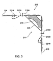
- bracket 211 comprises first mounting arm 213A terminating in first mating portion 221A and second mounting arm 213B terminating in second mating portion 221 B interconnected by intermediate portion 226 oriented at approximately 45° to wall 215 so that in use, intermediate portion 226 extends diagonally across existing timber moulding 219 (or cornice) to thereby allow mounting of removable cornice 212 over timber moulding 219 (or cornice).
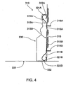
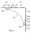
- FIGS 4 and 5 there are described examples where the cornice is not mounted over an existing cornice.
- cornice assembly 310 comprises an cornice in the form of skirting board 330, first bracket 311A and second bracket 311B.
- Brackets 311A and 311B respectively have mounting arms 313A and 313B mounted to wall 315 by respective screws 316A, 316B.
- Bracket 311 B is positioned so that base 332 of skirting board 330 is flush with floor 331.
- Channels 322A and 3228 connect with respective open loop ends 321A, 321B of brackets 311A, 311B to thereby removably mount skirting board 330 to wall 315.
- removably mountable cornice assembly 410 comprises cornice 412, first bracket 411A and second bracket 411B having respective mounting arms 413A and 413B mountable to ceiling 414 and wall 415, respectively, Mounting arm 413A and mounting arm 413B are mounted by way of respective screws 416A, 416B extending through respective apertures 417A, 41, 7B. Mounting arm 413A and mounting arm 413B respectively terminate in open loops 421 A and 421 B that constitute mating portions of brackets 411A and 411B.
- Cornice 412 has complementary mating portions in the form of channels 422A and 422B that releasably engage open loop ends 421A and 421 B of brackets 411A and 411B respectively.
- bracket 11 is shown.
- brackets 511A and 511B respectively terminate in mating portions In the form of nubs 521A and 521B. These mating portions releasably engage complementary mating portions of cornice 512 in the form of channels 522A and 522B.
- bracket 511 has mounting arm 513 with scallop or recess 540 in which is located aperture 517 so that bracket 511 can readily be mounted flush with wall 514 or ceiling 515.
- bracket 611A terminates in a mating portion in the form of step 821A that releasably engages complementary mating portion 622A of cornice 612.
- Mounting arm 613A is tapered so that wedge-end 660 can be inserted, for example, in gap 660 at junction 635 of wall 615 and celling 614.
- Bracket 611A also has scallop or recess 640 in which is located aperture 617A through which screw 616A mounts bracket 811A to ceiling 614. It will also be apparent from FIG. 7 that bracket 611A may be used with another bracket embodiment such as bracket 611 B.
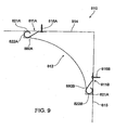
- mitre block 770 is located in a corner formed by walls 715A, 715B and ceiling (not shown), mitre block 770 could also be used to connect adjoining cornices 712A and 712B along wall 714A, for example, rather than in the corner between adjacent walls 715A, 715B.
- Mitre block 770 has mitres 771A and 771B that receive and accommodate ends 772A and 772B of respective corner-joined cornices 712A and 712B.
- Mitres 771A and 771 B may be readily created to accommodate a particular cross-sectional profile of cornices 712A and 712B.
- Another feature of mitre block 770 would be cut-out portions (not shown) that allow the corner block to be fitted over an existing cornice.
- Mitre block 770 may also have surface patterns, etchings, sculpturing or other ornamentation (not shown) that adds to the visual attractiveness of the mounted cornices,
- cornice junctions may be finished by normal 45 corner mitring.
- other decorative devices such as ornamental strips attachable at joins formed by ends of adjacent cornices 712A and 7128.
- use of blocks, ornamental strips, arches, covings and other finishes such as described in Australian Patent 548675 and Australian Patent 560796 which are each incorporated herein by reference.
- cornice 812 is shown which may be particularly useful when cornice 812 is formed of a relatively flexible material such as extruded plastic.
- Channels 822A and 822B of cornice 812 have respective ridges 880A and 880B that extend at least partly along the length thereof, so that in use, a portion of each of ridges 880A and 880B bears against open respective loops 821A and 821B of bracket 811A and 811B to facilitate firm engagement between brackets 811A and 811 B and cornice 812.
- the location of ridges 880A and 880B may also vary compared to that shown in FIG.
- channel 822A and/or 8228 may have respective ridges 880A and/or 880B, without there necessarily being a ridge 880 In each channel 822.
- ridges 880A and 880B extend along the entire length of channels 822A and/or 822B, for example there may be a plurality of shorter channels 880, In order to sufficiently contact bracket 811.
- the present invention provides a wall or ceiling cornice and mounting bracket therefor that can be readily installed by persons without the need for tradesman-like skills.
- the cornice of the invention therefore provides a useful alternative to traditional plaster cornices, the latter requiring considerable skill for installation. Ready installation is particularly enhanced given that existing cornices need not be removed, which also has the advantage that the "original" ornamental features of a home need not be destroyed during renovation. Furthermore, no adhesive, contact cement or plaster Is required, so that the cornice of the invention can be removably mounted with ease.
- the visual appeal of the mounted cornice assembly is also superior to the prior art as the mounted cornice effectively obscures the brackets from view.
- the cornice of the invention can therefore be removably Installed to cover and replace an existing cornice.
- mounting brackets of the invention can be readily adapted in terms of shape and dimension according to the cornice to be mounted and the existing cornice to be covered.
Claims (16)
- Procédé de montage de manière amovible d'une corniche (12 ; 112) sur au moins un panneau de construction (14, 15 ; 114, 115 ; 214 ; 215) afin de recouvrir au moins partiellement une corniche existante (18, 118) montée sur ledit panneau ou chacun desdits panneaux de construction, ledit procédé comportant les étapes de :(i) montage de manière amovible d'un ou plusieurs crochets (11A, 11B ; 111) sur ledit panneau ou chacun desdits panneaux de construction (14, 15 ; 114, 115 ; 214, 215), un ou plusieurs crochets de montage étant positionnés par rapport à ladite corniche existante (18 ; 118) de telle sorte que lesdits un ou plusieurs crochets permettent le montage de ladite corniche (12 ; 112) de manière à recouvrir au moins partiellement ladite corniche existante (18 ; 118) ; et(ii) assemblage de manière amovible de parties conjuguées complémentaires (22A, 22B ; 122B) de ladite corniche avec les parties conjuguées respectives (21A, 21B ; 121A, 121B) desdits un ou plusieurs crochets (11A, 11B ; 111) afin de monter ainsi de manière amovible ladite corniche sur ledit panneau ou chacun desdits panneaux de construction afin de recouvrir ainsi au moins partiellement ladite corniche existante (18 ; 118).
- Procédé selon la revendication 1, dans lequel chacun desdits crochets comprend un bras de montage (13A, 13B; 113A, 113B) et ladite partie conjuguée (21A, 21 B).
- Procédé selon la revendication 1, dans lequel ladite partie conjuguée dudit crochet est une boucle ouverte (21A, 21 B) pouvant être couplée à un canal complémentaire (22A, 22B) de ladite corniche.
- Procédé selon la revendication 1, dans lequel ladite partie conjuguée dudit crochet est une protubérance (521A, 521 B) pouvant être couplée à un canal complémentaire (522A, 522B) de ladite corniche.
- Procédé selon la revendication 1, dans lequel ladite partie conjuguée dudit crochet est une palette (621A) pouvant être couplée à un canal complémentaire (622A) de ladite corniche.
- Procédé selon la revendication 1, dans lequel ladite corniche comprend des parties conjuguées complémentaires sous la forme de deux canaux parallèles.
- Procédé selon la revendication 6, dans lequel la corniche comprend, en outre, une strie (880A, 880B) s'étendant au moins partiellement le long de l'un desdits canaux de telle sorte qu'en utilisation, une partie de ladite strie porte contre ladite partie conjuguée dudit crochet afin de faciliter le couplage entre ledit crochet et ladite corniche.
- Procédé selon la revendication 7, dans lequel ledit crochet comprend un premier bras de montage (213A) et un deuxième bras de montage (213B) reliés entre eux par une partie intermédiaire (226) qui est montée de manière à s'étendre diagonalement à travers ladite corniche existante montée au niveau d'une jonction entre des premier et second desdits panneaux de construction.
- Ensemble de corniche pouvant être monté de manière amovible sur un ou plusieurs panneaux de construction, ledit ensemble de corniche comportant une ou plusieurs corniches (12, 112) et un ou plusieurs crochets (11A, 11B ; 111), dans lequel lesdits crochets comprennent chacun au moins une partie conjuguée (21A, 21 B, 121A, 121B) adaptée afin de s'assembler de manière amovible sur une partie conjuguée complémentaire (22A, 22B, 122B) desdites une ou plusieurs corniches (12 ; 112), caractérisé en ce que lesdites une ou plusieurs corniches sont adaptées afin de recouvrir au moins partiellement une corniche existante (18 ; 118) montée sur lesdits un ou plusieurs panneaux de construction (14, 15 ; 114, 115 ; 214, 215).
- Ensemble de corniche selon la revendication 9, dans lequel chacun desdits crochets comprend un bras de montage (13A, 13B ; 113A, 113B) et ladite partie conjuguée (21A, 21 B).
- Ensemble de corniche selon la revendication 10, dans lequel ladite partie conjuguée dudit crochet est une boucle ouverte (21A, 21B) pouvant être couplée à un canal complémentaire (22A, 22B) de ladite corniche.
- Ensemble de corniche selon la revendication 10, dans lequel ladite partie conjuguée dudit crochet est une protubérance (521A, 521B) pouvant être couplée à un canal complémentaire (522A, 522B) de ladite corniche.
- Ensemble de corniche selon la revendication 10, dans lequel ladite partie conjuguée dudit crochet est une palette (621A) pouvant être couplée à un canal complémentaire (622A) dudit ornement.
- Ensemble de corniche selon la revendication 10, dans lequel ladite corniche comprend des parties conjuguées complémentaires sous la forme de deux canaux parallèles.
- Ensemble de corniche selon la revendication 14, dans lequel la corniche comprend, en outre, une arête (880A, 880B) s'étendant au moins partiellement le long de l'un desdits canaux de telle sorte qu'en utilisation, une partie de ladite strie porte contre ladite partie conjuguée dudit crochet afin de faciliter le couplage entre ledit crochet et ladite corniche.
- Ensemble de corniche selon la revendication 15, dans lequel ledit crochet comprend un premier bras de montage (213A) et un deuxième bras de montage (213B) reliés entre eux par une partie intermédiaire (226) qui est adaptée de manière à s'étendre diagonalement à travers ladite corniche existante montée au niveau d'une jonction entre un premier et un second desdits panneaux de construction.
Applications Claiming Priority (3)
| Application Number | Priority Date | Filing Date | Title |
|---|---|---|---|
| AUPR550701 | 2001-06-06 | ||
| AUPR5507A AUPR550701A0 (en) | 2001-06-06 | 2001-06-06 | Cornice and bracket |
| PCT/AU2002/000697 WO2002099224A1 (fr) | 2001-06-06 | 2002-05-31 | Ornement et support |
Publications (3)
| Publication Number | Publication Date |
|---|---|
| EP1442184A1 EP1442184A1 (fr) | 2004-08-04 |
| EP1442184A4 EP1442184A4 (fr) | 2007-07-04 |
| EP1442184B1 true EP1442184B1 (fr) | 2010-01-13 |
Family
ID=3829484
Family Applications (1)
| Application Number | Title | Priority Date | Filing Date |
|---|---|---|---|
| EP02727038A Expired - Lifetime EP1442184B1 (fr) | 2001-06-06 | 2002-05-31 | Méthode de montage amovible d'une corniche et ensemble de corniches |
Country Status (6)
| Country | Link |
|---|---|
| US (1) | US7040065B2 (fr) |
| EP (1) | EP1442184B1 (fr) |
| AT (1) | ATE455216T1 (fr) |
| AU (2) | AUPR550701A0 (fr) |
| DE (1) | DE60235104D1 (fr) |
| WO (1) | WO2002099224A1 (fr) |
Families Citing this family (10)
| Publication number | Priority date | Publication date | Assignee | Title |
|---|---|---|---|---|
| US7748179B2 (en) * | 2004-01-16 | 2010-07-06 | Tapco International Corporation | Decorative molding |
| US7451574B2 (en) * | 2005-03-07 | 2008-11-18 | Spexco, Llc | Crown molding |
| CA2666774A1 (fr) * | 2008-05-22 | 2009-11-22 | Royal Group, Inc. | Ensemble a moulurage |
| US20110023393A1 (en) * | 2009-07-31 | 2011-02-03 | Steven Hartman | Cornice |
| US20140338276A1 (en) * | 2011-07-11 | 2014-11-20 | Cory Halischuk | Fastening a Ceiling Trim |
| US9027299B2 (en) * | 2013-07-12 | 2015-05-12 | Joseph Mea | Themed modular ceiling and wall decor kit and system |
| US10598321B2 (en) * | 2016-05-24 | 2020-03-24 | Electrix, Llc | Cove lighting |
| CN105888203B (zh) * | 2016-06-25 | 2018-06-05 | 昆明市建筑设计研究院股份有限公司 | 一种防积污踢脚线结构 |
| US20180171645A1 (en) * | 2016-12-15 | 2018-06-21 | Old World Oddities LLC | Modular construction systems |
| US10202777B1 (en) * | 2017-08-08 | 2019-02-12 | Dennis Leavey | Securement devices for securing molding to a surface, and methods of securing molding to a surface |
Family Cites Families (16)
| Publication number | Priority date | Publication date | Assignee | Title |
|---|---|---|---|---|
| AU231382B2 (en) * | 1958-02-05 | 1959-08-06 | John Holt William | An improved metal wall skirting and door or window architrave |
| AU248026B2 (en) * | 1960-05-03 | 1963-11-13 | James Nihill Wallace | An improved beading for use with skirtings |
| US3707061A (en) * | 1971-04-23 | 1972-12-26 | Harold J Collette | Snap trim molding |
| GB8529541D0 (en) * | 1985-12-05 | 1986-01-08 | Enbee Products Ltd | Coving |
| US4723580A (en) * | 1986-10-24 | 1988-02-09 | Trautwein Jerry B | Cable sheath assembly |
| US5359817A (en) * | 1991-02-19 | 1994-11-01 | Transfer Flow International, Inc. | Architectural moldings of rigid thermoset polymer based material |
| US5592797A (en) * | 1992-07-20 | 1997-01-14 | Mid-America Building Products Corporation | Decorative molding strip system |
| US5457923A (en) * | 1992-07-20 | 1995-10-17 | Mid-America Building Products Corporation | Decorative molding strip |
| CA2099548A1 (fr) * | 1992-07-20 | 1994-01-21 | Richard Logan | Moulure decorative |
| GB9321820D0 (en) | 1993-10-22 | 1993-12-15 | Rees Aelwyn | Coving clip or cornice clip |
| GB2287043A (en) * | 1994-02-24 | 1995-09-06 | Joseph Patrick White | Clip-on coving |
| US5694726A (en) * | 1995-11-22 | 1997-12-09 | Wu; Ming-Hsin | Plastic fitting assembly |
| US5732747A (en) * | 1997-01-21 | 1998-03-31 | Icm Corporation | Cove molding cover for electrical cables |
| DE19723558C2 (de) * | 1997-06-05 | 2002-06-13 | Akzenta Paneele & Profile Gmbh | Sockelleiste mit Sockelclips |
| GB9810093D0 (en) * | 1998-05-12 | 1998-07-08 | Jones James | Detachable architectural features |
| US6643990B2 (en) * | 1999-12-29 | 2003-11-11 | James Jensen | Modular molding system |
-
2001
- 2001-06-06 AU AUPR5507A patent/AUPR550701A0/en not_active Abandoned
-
2002
- 2002-05-31 AT AT02727038T patent/ATE455216T1/de not_active IP Right Cessation
- 2002-05-31 US US10/480,007 patent/US7040065B2/en not_active Expired - Fee Related
- 2002-05-31 DE DE60235104T patent/DE60235104D1/de not_active Expired - Fee Related
- 2002-05-31 WO PCT/AU2002/000697 patent/WO2002099224A1/fr not_active Application Discontinuation
- 2002-05-31 EP EP02727038A patent/EP1442184B1/fr not_active Expired - Lifetime
- 2002-05-31 AU AU2002257372A patent/AU2002257372B2/en not_active Ceased
Also Published As
| Publication number | Publication date |
|---|---|
| US20040172897A1 (en) | 2004-09-09 |
| US7040065B2 (en) | 2006-05-09 |
| AU2002257372B2 (en) | 2005-04-28 |
| ATE455216T1 (de) | 2010-01-15 |
| EP1442184A1 (fr) | 2004-08-04 |
| EP1442184A4 (fr) | 2007-07-04 |
| WO2002099224A1 (fr) | 2002-12-12 |
| DE60235104D1 (de) | 2010-03-04 |
| AUPR550701A0 (en) | 2001-07-12 |
Similar Documents
| Publication | Publication Date | Title |
|---|---|---|
| US8522498B2 (en) | System and method for removably connecting trim to a wall or ceiling or both | |
| US7228663B2 (en) | Decorative trim assemblies | |
| US6385927B2 (en) | Decorative trim assemblies | |
| US6643990B2 (en) | Modular molding system | |
| US6751915B2 (en) | Kits and systems releasably attachable to a wall, and methods employing same | |
| CA2365895C (fr) | Moulure de socle en deux parties separables | |
| US20100018145A1 (en) | Decorative joint system | |
| EP1442184B1 (fr) | Méthode de montage amovible d'une corniche et ensemble de corniches | |
| EP2000611A2 (fr) | Système de joint décoratif | |
| CA2744022A1 (fr) | Corniche extrudee | |
| US6477818B1 (en) | Modular molding system | |
| US20030115813A1 (en) | Wall molding mounting structure and method | |
| US6755000B2 (en) | Plaster molding system | |
| US6913369B2 (en) | Wall or ceiling mountable device and wall structure incorporating device | |
| US20140174023A1 (en) | Apparatus for Trimming Interior Walls | |
| AU2002257372A1 (en) | Ornament and bracket | |
| US6463707B1 (en) | Decorative trim assemblies | |
| US20050210784A1 (en) | Molding system for improved appearance with simplified installation | |
| US5960600A (en) | Carpet-covered baseboard and method of use thereof | |
| GB2326429A (en) | Decorative embellishment for the walls of a building | |
| GB2274055A (en) | Threshold edging and/or stair nosing | |
| CN210263784U (zh) | 一种面饰收口顶角线组件 | |
| CN211080874U (zh) | 一种墙板固定件 | |
| WO2006122346A1 (fr) | Ensemble de jonction de corniches | |
| JP3590347B2 (ja) | 階段幅木 |
Legal Events
| Date | Code | Title | Description |
|---|---|---|---|
| PUAI | Public reference made under article 153(3) epc to a published international application that has entered the european phase |
Free format text: ORIGINAL CODE: 0009012 |
|
| 17P | Request for examination filed |
Effective date: 20040430 |
|
| AK | Designated contracting states |
Kind code of ref document: A1 Designated state(s): AT BE CH CY DE DK ES FI FR GB GR IE IT LI LU MC NL PT SE TR |
|
| AX | Request for extension of the european patent |
Extension state: AL LT LV MK RO SI |
|
| A4 | Supplementary search report drawn up and despatched |
Effective date: 20070605 |
|
| 17Q | First examination report despatched |
Effective date: 20070905 |
|
| GRAP | Despatch of communication of intention to grant a patent |
Free format text: ORIGINAL CODE: EPIDOSNIGR1 |
|
| RTI1 | Title (correction) |
Free format text: METHODE FOR REMOVABLY MOUNTING A CORNICE AND CORNICE ASSEMBLY |
|
| GRAS | Grant fee paid |
Free format text: ORIGINAL CODE: EPIDOSNIGR3 |
|
| GRAA | (expected) grant |
Free format text: ORIGINAL CODE: 0009210 |
|
| AK | Designated contracting states |
Kind code of ref document: B1 Designated state(s): AT BE CH CY DE DK ES FI FR GB GR IE IT LI LU MC NL PT SE TR |
|
| REG | Reference to a national code |
Ref country code: GB Ref legal event code: FG4D |
|
| REG | Reference to a national code |
Ref country code: CH Ref legal event code: EP |
|
| REG | Reference to a national code |
Ref country code: IE Ref legal event code: FG4D |
|
| REF | Corresponds to: |
Ref document number: 60235104 Country of ref document: DE Date of ref document: 20100304 Kind code of ref document: P |
|
| REG | Reference to a national code |
Ref country code: NL Ref legal event code: VDEP Effective date: 20100113 |
|
| PG25 | Lapsed in a contracting state [announced via postgrant information from national office to epo] |
Ref country code: AT Free format text: LAPSE BECAUSE OF FAILURE TO SUBMIT A TRANSLATION OF THE DESCRIPTION OR TO PAY THE FEE WITHIN THE PRESCRIBED TIME-LIMIT Effective date: 20100113 |
|
| PG25 | Lapsed in a contracting state [announced via postgrant information from national office to epo] |
Ref country code: PT Free format text: LAPSE BECAUSE OF FAILURE TO SUBMIT A TRANSLATION OF THE DESCRIPTION OR TO PAY THE FEE WITHIN THE PRESCRIBED TIME-LIMIT Effective date: 20100513 Ref country code: ES Free format text: LAPSE BECAUSE OF FAILURE TO SUBMIT A TRANSLATION OF THE DESCRIPTION OR TO PAY THE FEE WITHIN THE PRESCRIBED TIME-LIMIT Effective date: 20100424 Ref country code: NL Free format text: LAPSE BECAUSE OF FAILURE TO SUBMIT A TRANSLATION OF THE DESCRIPTION OR TO PAY THE FEE WITHIN THE PRESCRIBED TIME-LIMIT Effective date: 20100113 |
|
| PG25 | Lapsed in a contracting state [announced via postgrant information from national office to epo] |
Ref country code: FI Free format text: LAPSE BECAUSE OF FAILURE TO SUBMIT A TRANSLATION OF THE DESCRIPTION OR TO PAY THE FEE WITHIN THE PRESCRIBED TIME-LIMIT Effective date: 20100113 |
|
| PG25 | Lapsed in a contracting state [announced via postgrant information from national office to epo] |
Ref country code: GR Free format text: LAPSE BECAUSE OF FAILURE TO SUBMIT A TRANSLATION OF THE DESCRIPTION OR TO PAY THE FEE WITHIN THE PRESCRIBED TIME-LIMIT Effective date: 20100414 Ref country code: SE Free format text: LAPSE BECAUSE OF FAILURE TO SUBMIT A TRANSLATION OF THE DESCRIPTION OR TO PAY THE FEE WITHIN THE PRESCRIBED TIME-LIMIT Effective date: 20100113 Ref country code: BE Free format text: LAPSE BECAUSE OF FAILURE TO SUBMIT A TRANSLATION OF THE DESCRIPTION OR TO PAY THE FEE WITHIN THE PRESCRIBED TIME-LIMIT Effective date: 20100113 Ref country code: CY Free format text: LAPSE BECAUSE OF FAILURE TO SUBMIT A TRANSLATION OF THE DESCRIPTION OR TO PAY THE FEE WITHIN THE PRESCRIBED TIME-LIMIT Effective date: 20100113 |
|
| PLBE | No opposition filed within time limit |
Free format text: ORIGINAL CODE: 0009261 |
|
| STAA | Information on the status of an ep patent application or granted ep patent |
Free format text: STATUS: NO OPPOSITION FILED WITHIN TIME LIMIT |
|
| 26N | No opposition filed |
Effective date: 20101014 |
|
| PG25 | Lapsed in a contracting state [announced via postgrant information from national office to epo] |
Ref country code: MC Free format text: LAPSE BECAUSE OF NON-PAYMENT OF DUE FEES Effective date: 20100531 |
|
| REG | Reference to a national code |
Ref country code: CH Ref legal event code: PL |
|
| PG25 | Lapsed in a contracting state [announced via postgrant information from national office to epo] |
Ref country code: DK Free format text: LAPSE BECAUSE OF FAILURE TO SUBMIT A TRANSLATION OF THE DESCRIPTION OR TO PAY THE FEE WITHIN THE PRESCRIBED TIME-LIMIT Effective date: 20100113 |
|
| REG | Reference to a national code |
Ref country code: FR Ref legal event code: ST Effective date: 20110131 |
|
| PG25 | Lapsed in a contracting state [announced via postgrant information from national office to epo] |
Ref country code: CH Free format text: LAPSE BECAUSE OF NON-PAYMENT OF DUE FEES Effective date: 20100531 Ref country code: LI Free format text: LAPSE BECAUSE OF NON-PAYMENT OF DUE FEES Effective date: 20100531 |
|
| PG25 | Lapsed in a contracting state [announced via postgrant information from national office to epo] |
Ref country code: IT Free format text: LAPSE BECAUSE OF FAILURE TO SUBMIT A TRANSLATION OF THE DESCRIPTION OR TO PAY THE FEE WITHIN THE PRESCRIBED TIME-LIMIT Effective date: 20100113 |
|
| PG25 | Lapsed in a contracting state [announced via postgrant information from national office to epo] |
Ref country code: IE Free format text: LAPSE BECAUSE OF NON-PAYMENT OF DUE FEES Effective date: 20100531 Ref country code: DE Free format text: LAPSE BECAUSE OF NON-PAYMENT OF DUE FEES Effective date: 20101201 |
|
| PG25 | Lapsed in a contracting state [announced via postgrant information from national office to epo] |
Ref country code: FR Free format text: LAPSE BECAUSE OF NON-PAYMENT OF DUE FEES Effective date: 20100531 |
|
| PG25 | Lapsed in a contracting state [announced via postgrant information from national office to epo] |
Ref country code: LU Free format text: LAPSE BECAUSE OF NON-PAYMENT OF DUE FEES Effective date: 20100531 |
|
| PG25 | Lapsed in a contracting state [announced via postgrant information from national office to epo] |
Ref country code: TR Free format text: LAPSE BECAUSE OF FAILURE TO SUBMIT A TRANSLATION OF THE DESCRIPTION OR TO PAY THE FEE WITHIN THE PRESCRIBED TIME-LIMIT Effective date: 20100113 |
|
| PGFP | Annual fee paid to national office [announced via postgrant information from national office to epo] |
Ref country code: GB Payment date: 20130530 Year of fee payment: 12 |
|
| GBPC | Gb: european patent ceased through non-payment of renewal fee |
Effective date: 20140531 |
|
| PG25 | Lapsed in a contracting state [announced via postgrant information from national office to epo] |
Ref country code: GB Free format text: LAPSE BECAUSE OF NON-PAYMENT OF DUE FEES Effective date: 20140531 |