EP1441108A2 - Amortisseur pour stator de turbomachine - Google Patents
Amortisseur pour stator de turbomachine Download PDFInfo
- Publication number
- EP1441108A2 EP1441108A2 EP04250425A EP04250425A EP1441108A2 EP 1441108 A2 EP1441108 A2 EP 1441108A2 EP 04250425 A EP04250425 A EP 04250425A EP 04250425 A EP04250425 A EP 04250425A EP 1441108 A2 EP1441108 A2 EP 1441108A2
- Authority
- EP
- European Patent Office
- Prior art keywords
- damper
- seal
- stator segment
- medial section
- stator
- Prior art date
- Legal status (The legal status is an assumption and is not a legal conclusion. Google has not performed a legal analysis and makes no representation as to the accuracy of the status listed.)
- Granted
Links
Images


Classifications
-
- F—MECHANICAL ENGINEERING; LIGHTING; HEATING; WEAPONS; BLASTING
- F16—ENGINEERING ELEMENTS AND UNITS; GENERAL MEASURES FOR PRODUCING AND MAINTAINING EFFECTIVE FUNCTIONING OF MACHINES OR INSTALLATIONS; THERMAL INSULATION IN GENERAL
- F16J—PISTONS; CYLINDERS; SEALINGS
- F16J15/00—Sealings
- F16J15/44—Free-space packings
- F16J15/441—Free-space packings with floating ring
-
- F—MECHANICAL ENGINEERING; LIGHTING; HEATING; WEAPONS; BLASTING
- F01—MACHINES OR ENGINES IN GENERAL; ENGINE PLANTS IN GENERAL; STEAM ENGINES
- F01D—NON-POSITIVE DISPLACEMENT MACHINES OR ENGINES, e.g. STEAM TURBINES
- F01D11/00—Preventing or minimising internal leakage of working-fluid, e.g. between stages
- F01D11/001—Preventing or minimising internal leakage of working-fluid, e.g. between stages for sealing space between stator blade and rotor
-
- F—MECHANICAL ENGINEERING; LIGHTING; HEATING; WEAPONS; BLASTING
- F01—MACHINES OR ENGINES IN GENERAL; ENGINE PLANTS IN GENERAL; STEAM ENGINES
- F01D—NON-POSITIVE DISPLACEMENT MACHINES OR ENGINES, e.g. STEAM TURBINES
- F01D11/00—Preventing or minimising internal leakage of working-fluid, e.g. between stages
- F01D11/08—Preventing or minimising internal leakage of working-fluid, e.g. between stages for sealing space between rotor blade tips and stator
-
- F—MECHANICAL ENGINEERING; LIGHTING; HEATING; WEAPONS; BLASTING
- F01—MACHINES OR ENGINES IN GENERAL; ENGINE PLANTS IN GENERAL; STEAM ENGINES
- F01D—NON-POSITIVE DISPLACEMENT MACHINES OR ENGINES, e.g. STEAM TURBINES
- F01D25/00—Component parts, details, or accessories, not provided for in, or of interest apart from, other groups
- F01D25/04—Antivibration arrangements
-
- F—MECHANICAL ENGINEERING; LIGHTING; HEATING; WEAPONS; BLASTING
- F01—MACHINES OR ENGINES IN GENERAL; ENGINE PLANTS IN GENERAL; STEAM ENGINES
- F01D—NON-POSITIVE DISPLACEMENT MACHINES OR ENGINES, e.g. STEAM TURBINES
- F01D5/00—Blades; Blade-carrying members; Heating, heat-insulating, cooling or antivibration means on the blades or the members
- F01D5/12—Blades
- F01D5/26—Antivibration means not restricted to blade form or construction or to blade-to-blade connections or to the use of particular materials
-
- F—MECHANICAL ENGINEERING; LIGHTING; HEATING; WEAPONS; BLASTING
- F01—MACHINES OR ENGINES IN GENERAL; ENGINE PLANTS IN GENERAL; STEAM ENGINES
- F01D—NON-POSITIVE DISPLACEMENT MACHINES OR ENGINES, e.g. STEAM TURBINES
- F01D9/00—Stators
- F01D9/02—Nozzles; Nozzle boxes; Stator blades; Guide conduits, e.g. individual nozzles
- F01D9/04—Nozzles; Nozzle boxes; Stator blades; Guide conduits, e.g. individual nozzles forming ring or sector
- F01D9/042—Nozzles; Nozzle boxes; Stator blades; Guide conduits, e.g. individual nozzles forming ring or sector fixing blades to stators
-
- F—MECHANICAL ENGINEERING; LIGHTING; HEATING; WEAPONS; BLASTING
- F05—INDEXING SCHEMES RELATING TO ENGINES OR PUMPS IN VARIOUS SUBCLASSES OF CLASSES F01-F04
- F05D—INDEXING SCHEME FOR ASPECTS RELATING TO NON-POSITIVE-DISPLACEMENT MACHINES OR ENGINES, GAS-TURBINES OR JET-PROPULSION PLANTS
- F05D2240/00—Components
- F05D2240/10—Stators
- F05D2240/11—Shroud seal segments
-
- F—MECHANICAL ENGINEERING; LIGHTING; HEATING; WEAPONS; BLASTING
- F05—INDEXING SCHEMES RELATING TO ENGINES OR PUMPS IN VARIOUS SUBCLASSES OF CLASSES F01-F04
- F05D—INDEXING SCHEME FOR ASPECTS RELATING TO NON-POSITIVE-DISPLACEMENT MACHINES OR ENGINES, GAS-TURBINES OR JET-PROPULSION PLANTS
- F05D2240/00—Components
- F05D2240/70—Slinger plates or washers
-
- F—MECHANICAL ENGINEERING; LIGHTING; HEATING; WEAPONS; BLASTING
- F05—INDEXING SCHEMES RELATING TO ENGINES OR PUMPS IN VARIOUS SUBCLASSES OF CLASSES F01-F04
- F05D—INDEXING SCHEME FOR ASPECTS RELATING TO NON-POSITIVE-DISPLACEMENT MACHINES OR ENGINES, GAS-TURBINES OR JET-PROPULSION PLANTS
- F05D2260/00—Function
- F05D2260/30—Retaining components in desired mutual position
- F05D2260/38—Retaining components in desired mutual position by a spring, i.e. spring loaded or biased towards a certain position
Definitions
- This invention relates to a damper for a stator vane of a gas turbine engine. Specifically, this invention relates to a damper for reducing vibration between a vane assembly and a seal secured to the vane assembly.
- Gas turbine engines include alternating stages of rotating blades and stationary vanes.
- Each vane stage comprises a plurality of stator segments.
- a segment could include a plurality of vanes extending between an outer platform and an inner platform.
- Stator segments are commonly formed by casting or by brazing.
- the inner platform typically includes relief slits between adjacent vanes. These relief slits also help isolate vanes from vibration modes of adjacent vanes.
- the stator segment also includes a damper to reduce vibration amplitudes, thereby helping prevent vane cracking,
- the damper is typically formed into a spring by passing sheet metal through punch-press dies or forming rolls.
- Conventional damper designs have numerous drawbacks.
- First, conventional damper shapes can have asymmetric shapes that can apply unequalized damping forces to the mating surfaces on the stator assembly. Unequalized damping forces reduces the effectiveness of the damper.
- Second, conventional damper shapes require multiple passes through the punch-press dies or forming rolls. Multiple passes through the forming machines increases manufacturing costs.
- Third, the shape of conventional dampers ( i . e . almost tubular) requires more material than is necessary for damping purposes. This additional material increases the weight of the engine.
- a stator assembly comprising: a stator segment; a seal mounted to said stator segment; and a damper between the stator segment and the seal.
- the damper has: a medial section; and opposed arms extending from the medial section. The medial section engages one of the stator segment and the seal and the opposed arms engage the other of the stator segment and the seal.
- a damper for reducing vibration between a stator segment and a seal comprising: a medial section for engaging one of the stator segment and the seal; and opposed arms extending from the medial section for engaging the other of the stator segment and the seal.
- a method of making a damper for reducing vibration between a stator segment and a seal comprising the steps of: providing a sheet of material having a medial section and opposed arms extending from the medial section; forming a bend at the medial section so that the medial section can engage one of the stator segment and the seal; and forming a bend at each of said arms so that the arms can engage the other of the stator segment and the seal.
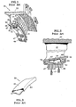
- Figures 1 and 2 display a conventional stator assembly 30 used in the compressor section of a gas turbine engine.
- the assembly 30 is a vane segment having a plurality of vanes 31 extending between a radially outer platform 33 and a radially inner platform 35.
- the assembly 30 is typically made by a casting or a brazement.
- a plurality of relief slits 37 in the inner platform 35 help reduce the build-up of stress caused by temperature gradients in the vanes 31 and platforms 33, 35 during engine operation.
- the inner platform 35 includes an upstream flange 39 and a downstream flange 41.
- the flanges 39, 41 respectively include channels 43, 45 that accept an inner air seal 47.
- the inner air seal 47 comprises the seal land of a labyrinth seal assembly. Labyrinth seals prevent fluid leakage between a stationary component (e . g . stator assembly 30) and a rotating component (e.g. the compressor rotor).
- the seal land 47 includes an abradable material 49 (such as a metal honeycomb) mounted to a support plate 51. Seal teeth T extend from the compressor rotor (not shown), face the abradable material and define a clearance therebetween. The clearance determines the effectiveness of the labyrinth seal.
- abradable material 49 such as a metal honeycomb
- the support plate 51 includes opposed feet 53, 55 that correspond to the channels 43, 45 in the inner platform 35.
- the inner platform 35 and the inner air seal 47 define a cavity 57.
- An arcuate damper 59 resides in the cavity 57.
- An example of this damper 59 is part number 4319363 available from Pratt & Whitney of East Hartford, Connecticut
- FIG. 3 is a detailed view of the damper 59.
- the damper 59 includes opposed arms 61, 63 extending from a central section 65.
- the damper 59 is formed from a sheet (not shown) of metal.
- a forming die (not shown) folds the arms 61, 63 away from the central section 65.
- another forming die (not shown) bends the damper into an arcuate shape.
- the damper 59 requires compression for placement within the cavity 57. After insertion, this compression allows the damper 59 to provide the appropriate amount of loading to the inner platform 35 and the inner air seal 47 for reducing vibration. As seen in Figure 2, the damper 59 contacts the inner platform 35 at two locations 67, 69. Similarly, the damper 59 contacts the inner air seal 47 at two locations 71, 73.
- this stator assembly 30 is the inability of the damper 59 to apply equal loading applied to the inner platform 35 at locations 67, 69. Due to the shape of the flowpath for core flow through the engine, the cavity 57 has a wedge shape. As seen in Figure 2, the cavity 57 enlarges in the downstream direction. This cavity shape requires the damper 59 to have an asymmetric shape. The asymmetric shape of the damper 59 produces unequal forces between the damper 59 and the corresponding mating surfaces of the inner platform 35. Such unequal loading reduces the effectiveness of the damper 59.
- the unequal loading of the damper 59 produces a torsional deformation in the vane when the vane vibrates in the flexing mode (relative to the engine circumferential direction).
- the unequal loading of the damper 59 produces a flexural deformation in the vane when the vane vibrates in a torsional mode.
- Figures 4 and 5 display another conventional stator assembly 90. Similar to the aforementioned assembly 30, the assembly 90 includes a plurality of vanes 91 extending between a radially outer platform (not shown) and a radially inner platform 93. The inner platform 93 accepts an inner air seal 95.
- An arcuate damper 97 resides between the inner platform 93 and the inner air seal 95.
- An example of this damper 97 is part number 55H401 available from Pratt & Whiney of East Hartford, Connecticut.
- FIG. 5 is a detailed view of the damper 97.
- the damper 97 includes opposed arms 99, 101 extending from a central section 103.
- the damper 97 is formed from a sheet of metal (not shown).
- a forming die (not shown) folds the arms 99, 101 over the central section 103.
- another forming die (not shown) bends the damper into an arcuate shape. Slots 105 help reduce the bending stiffness of the damper 97, which permits more even distribution of load into each of the individual vane platforms 35.
- the damper 97 requires compression for placement between the inner platform 93 and the inner air seal 95. After insertion, this compression allows the damper 97 to provide the appropriate amount of loading to the inner platform 93 and inner air seal 95 for reducing vibration. As seen in Figure 4, the damper 97 contacts the inner platform 93 at two locations 107, 109. The damper 97 also contacts the inner air seal 95 at two locations 111, 113.
- the damper 97 has several drawbacks. First, forming the damper 97 requires multiple passes through the tooling equipment.
- the damper 97 can function only in symmetric cavities. With symmetric cavities, dampers can provide equal damper loading to the contact points 107, 109. In order to use the damper 97, the designer would have to modify the asymmetric cavity with additional structure to create a symmetric cavity. This, however, introduces unnecessary weight and cost to the engine.
- FIGS. 6 and 7 display one alternative embodiment of a stator assembly 150 of the present invention.
- the following description omits features of the stator assembly 150 previous described with respect to assemblies 30, 90 that are unnecessary for an understanding of the present invention.
- the stator assembly 150 of the present invention includes a plurality of vanes 151 extending between a radially outer platform 153 and a radially inner platform 155.
- the assembly 150 is typically made by casting.
- the inner platform 155 accepts an inner air seal 157.
- the inner air seal 157 comprises the seal land portion of a labyrinth seal assembly.
- the other portion of the labyrinth seal comprises seal teeth T on a rotating component ( e . g . the compressor rotor).
- the labyrinth seal prevents fluid leakage between the stator assembly 150 and the rotor.
- the clearance between the teeth T and the inner air seal 157 determines the effectiveness of the labyrinth seal.
- the inner platform 155 and the inner air seal 157 define a cavity 159. Due to the shape of the flowpath for core flow through the engine, the cavity 159 has a wedge shape. As seen in Figure 6, the cavity 159 enlarges in the downstream direction. An arcuate damper 161 resides in the cavity 159. Figure 7 provides a detailed view of the damper 161.
- the damper 161 includes opposed arms 163, 165 extending from a medial or central section 167.
- the damper 161 of the present invention can be formed in one pass through forming rolls (not shown) or a punch-press (not shown).
- the less complex shape of the damper 161 allows formation in one pass.
- the single pass through the forming rollspunch press creates bends 169, 171, 173 and creates the arcuate curve in the damper 161.
- the forming rolls/punch press can also create slots 175 when forming the bends 169, 171, 173 and arcuate curve.
- the slots 175 could be provided to the sheet metal before passing through the forming rolls/punch press.
- the damper 161 requires compression for placement within the cavity 15 9 and to create the required load for vibration damping.
- the damper 161 contacts the inner platform 155 and the inner air seal 157 at three locations. These contact locations correspond to the bends 169, 171, 173. Specifically, the damper 161 contacts the platform 155 at two points, the bends 169, 173 on the arms 163, 165, and the seal 157 at one point, the bend 171 on the central section 167.
- the damper 161 can better compensate for unequal loading applied to the inner platform 155 at bends 169,173. Should unequal loading exist on the arms 163, 165, the damper 161 will, in response, roll along the mating surface of the inner air seal 157 at bend 171 of the central section 167. The damper 161 will stop rolling along the bend 171 when the loading applied to the inner platform at bends 169, 173 equalizes.
- the damper 161 has an asymmetric shape to accommodate the tapered shape of the cavity 159.
- the asymmetric design is more amenable to the adjustment of geometric attributes of the damper 161 to produce the desired loads against the platform 155.
- This configuration also more readily accommodates variation in the cavity between the platform 155 and the seal 157 created during manufacture or by wear during engine operation.
- FIGS 8 and 9 display another alternative embodiment of the present invention, a stator assembly 190.
- the stator assembly 190 of the present invention includes a plurality of vanes 191 extending between a radially outer platform 193 and a radially inner platform 195.
- the assembly 190 is typically made by casting.
- the inner platform 195 accepts an inner air seal 197.
- the inner air seal 197 faces seal teeth T on a rotating component (e.g. the compressor rotor) to define a labyrinth seal.
- the clearance between the teeth T and the inner air seal 197 determines the effectiveness of the labyrinth seal.
- the inner platform 195 and in inner air seal 197 defme a cavity 199.
- the cavity 199 has a uniform size.
- An arcuate damper201 resides in the cavity 199.
- Figure 9 provides a detailed view of the damper 201.
- the damper 201 has a different shape than damper 161 in order to function properly in cavity 199. Comparing Figures 6 and 8, damper 201 is shallower (in the radial direction) than damper 161. Damper 201 is shallower since the cavity 199 is shallower than cavity 159. Since the cavity has a uniform size (i.e. no taper in the downstream direction), the damper 201 is symmetric.
- the damper 201 includes opposed arms 203, 205 extending from a central section 207.
- the damper 201 is formed from a sheet of metal (not shown) in the same manner as described above with damper 161.
- the forming process creates bends 209, 211, 213 and creates the arcuate curve in the damper 201.
- the forming process can also create slots 215 when forming the bends 169, 171, 173 and arcuate curve. Alternatively, the slots 215 could be provided to the sheet metal before passing through the forming rolls/punch press.
- the damper 201 also requires compression for placement within the cavity 199 and to create the required load for vibration damping.
- the damper 201 contacts the inner platform 195 and the inner air seal 197 at three locations. These contact locations correspond to the bends 209, 211, 213. Specifically, the damper 201 contacts the platform 195 at two points, the bends 209, 213 on the arms 203, 205, and the seal 197 at one point, the bend 211 on the central section 207.
- the damper 201 can better compensate for unequal loading applied to the inner platform 195 at bends 209, 213. Should unequal loading exist on the arms 203, 205, the damper 201 will, in response, roll along the mating surface of the inner air seal 197 at bend 211 of the central section 207. The damper 201 will stop rolling along the bend 211 when the loading applied to the inner platform at bends 209, 213 equalizes.
- the dampers of the present invention contact the inner platform of the stator at two locations and the seal at one location.
- the widely, and equally, spaced (about the vane axis) contact points provide sufficient contact force to resist torsion of the vane.
- the dampers could be designed in an opposite arrangement (not shown) so that the damper contacts the inner platform of the stator at one location and the seal at two locations. Such an arrangement is useful, for example, in instances where stress caused by inner air seal vibration may be the prime concern.
Landscapes
- Engineering & Computer Science (AREA)
- General Engineering & Computer Science (AREA)
- Mechanical Engineering (AREA)
- Structures Of Non-Positive Displacement Pumps (AREA)
- Turbine Rotor Nozzle Sealing (AREA)
Applications Claiming Priority (2)
| Application Number | Priority Date | Filing Date | Title |
|---|---|---|---|
| US248532 | 1994-05-31 | ||
| US10/248,532 US7291946B2 (en) | 2003-01-27 | 2003-01-27 | Damper for stator assembly |
Publications (3)
| Publication Number | Publication Date |
|---|---|
| EP1441108A2 true EP1441108A2 (fr) | 2004-07-28 |
| EP1441108A3 EP1441108A3 (fr) | 2006-12-20 |
| EP1441108B1 EP1441108B1 (fr) | 2011-03-02 |
Family
ID=32592788
Family Applications (1)
| Application Number | Title | Priority Date | Filing Date |
|---|---|---|---|
| EP04250425A Expired - Fee Related EP1441108B1 (fr) | 2003-01-27 | 2004-01-27 | Amortisseur pour stator de turbomachine |
Country Status (3)
| Country | Link |
|---|---|
| US (1) | US7291946B2 (fr) |
| EP (1) | EP1441108B1 (fr) |
| DE (1) | DE602004031570D1 (fr) |
Cited By (18)
| Publication number | Priority date | Publication date | Assignee | Title |
|---|---|---|---|---|
| WO2005078242A1 (fr) * | 2004-02-11 | 2005-08-25 | Mtu Aero Engines Gmbh | Systeme amortisseur pour aubes directrices |
| EP2019188A1 (fr) * | 2007-07-25 | 2009-01-28 | Siemens Aktiengesellschaft | Etage de rotor comprenant un dispositif d'amortissement |
| EP2048324A1 (fr) * | 2007-10-11 | 2009-04-15 | Snecma | Stator de turbine pour turbomachine d'aeronef integrant un dispositif d'amortissement de vibrations |
| CN102132047A (zh) * | 2008-12-25 | 2011-07-20 | 三菱重工业株式会社 | 涡轮叶片及燃气轮机 |
| FR2971022A1 (fr) * | 2011-02-02 | 2012-08-03 | Snecma | Etage redresseur de compresseur pour une turbomachine |
| WO2013115874A3 (fr) * | 2011-11-11 | 2013-09-26 | United Technologies Corporation | Joint d'étanchéité de turbomachine |
| EP2613021A3 (fr) * | 2012-01-05 | 2013-11-13 | United Technologies Corporation | Amortisseur à ressort d'aube de stator |
| EP2696038A1 (fr) * | 2012-08-07 | 2014-02-12 | MTU Aero Engines GmbH | Grille d'aubes directrices pour une turbomachine |
| EP2722487A1 (fr) * | 2012-10-18 | 2014-04-23 | MTU Aero Engines GmbH | Combinaison de composant de boîtier par complémentarité de forme et son procédé de fabrication |
| EP2787180A1 (fr) * | 2013-04-04 | 2014-10-08 | MTU Aero Engines GmbH | Agencement d'aubes directrices pour une turbomachine |
| US8899914B2 (en) | 2012-01-05 | 2014-12-02 | United Technologies Corporation | Stator vane integrated attachment liner and spring damper |
| WO2014207058A1 (fr) | 2013-06-28 | 2014-12-31 | Siemens Aktiengesellschaft | Segment de bague d'étanchéité destiné à un stator de turbine |
| EP2811117A3 (fr) * | 2013-06-05 | 2015-02-25 | Rolls-Royce Deutschland Ltd & Co KG | Anneau de renforcement pour une turbomachine |
| FR3013759A1 (fr) * | 2013-11-26 | 2015-05-29 | Snecma | Secteur de couronne d'equilibrage, partie de turbomachine equilibree et turbomachine |
| EP3073055A3 (fr) * | 2015-03-24 | 2016-11-02 | United Technologies Corporation | Amortisseur pour ensemble stator et ensemble stator |
| EP3315728A1 (fr) * | 2016-10-26 | 2018-05-02 | MTU Aero Engines GmbH | Gedämpfte leitschaufellagerung |
| EP3456975A1 (fr) * | 2017-09-18 | 2019-03-20 | Thermodyn SAS | Machine rotative comprenant un système d'amortissement de bague d'étanchéité |
| US11506382B2 (en) | 2019-09-12 | 2022-11-22 | General Electric Company | System and method for acoustic dampers with multiple volumes in a combustion chamber front panel |
Families Citing this family (35)
| Publication number | Priority date | Publication date | Assignee | Title |
|---|---|---|---|---|
| US7196438B2 (en) * | 2005-05-12 | 2007-03-27 | Emerson Electric Co. | Resilient isolation members and related methods of reducing acoustic noise and/or structural vibration in an electric machine |
| US7762761B2 (en) * | 2005-11-30 | 2010-07-27 | General Electric Company | Methods and apparatus for assembling turbine nozzles |
| DE102007009134A1 (de) * | 2007-02-24 | 2008-08-28 | Mtu Aero Engines Gmbh | Verdichter einer Gasturbine |
| US8038388B2 (en) * | 2007-03-05 | 2011-10-18 | United Technologies Corporation | Abradable component for a gas turbine engine |
| US8485785B2 (en) * | 2007-07-19 | 2013-07-16 | Siemens Energy, Inc. | Wear prevention spring for turbine blade |
| US8240120B2 (en) * | 2007-10-25 | 2012-08-14 | United Technologies Corporation | Vibration management for gas turbine engines |
| DE102008051544B4 (de) * | 2008-10-14 | 2012-12-27 | Continental Automotive Gmbh | Spindeltrieb mit Verdrehsicherung |
| US8087881B1 (en) | 2008-11-22 | 2012-01-03 | Florida Turbine Technologies, Inc. | Damped stator assembly |
| ATE556195T1 (de) * | 2009-02-05 | 2012-05-15 | Siemens Ag | Ringförmige schaufelanordnung für einen gasturbinenmotor |
| US8157507B1 (en) * | 2010-01-19 | 2012-04-17 | Florida Turbine Technologies, Inc. | Damped stator assembly |
| FR2961554B1 (fr) * | 2010-06-18 | 2012-07-20 | Snecma | Secteur angulaire de redresseur pour compresseur de turbomachine, redresseur de turbomachine et turbomachine comprenant un tel secteur |
| FR2961553B1 (fr) * | 2010-06-18 | 2012-08-31 | Snecma | Secteur angulaire de redresseur pour compresseur de turbomachine, redresseur de turbomachine et turbomachine comprenant un tel secteur |
| FR2962481B1 (fr) * | 2010-07-12 | 2012-08-31 | Snecma Propulsion Solide | Amortisseur de vibrations a bras de levier pour aube d'un rotor de moteur a turbine a gaz |
| US20130028713A1 (en) * | 2011-07-25 | 2013-01-31 | General Electric Company | Seal for turbomachine segments |
| US8926269B2 (en) * | 2011-09-06 | 2015-01-06 | General Electric Company | Stepped, conical honeycomb seal carrier |
| US8920116B2 (en) * | 2011-10-07 | 2014-12-30 | Siemens Energy, Inc. | Wear prevention system for securing compressor airfoils within a turbine engine |
| US20130134678A1 (en) * | 2011-11-29 | 2013-05-30 | General Electric Company | Shim seal assemblies and assembly methods for stationary components of rotary machines |
| FR2991372B1 (fr) * | 2012-06-04 | 2014-05-16 | Snecma | Roue de turbine dans une turbomachine |
| WO2014122371A1 (fr) * | 2013-02-05 | 2014-08-14 | Snecma | Aubage de distribution de flux comportant une platine d'étanchéité amélioré |
| EP2881545B1 (fr) * | 2013-12-04 | 2017-05-31 | MTU Aero Engines GmbH | Élément d'étanchéité, dispositif d'étanchéité et turbomachine |
| US20150260465A1 (en) * | 2014-03-17 | 2015-09-17 | Borgwarner Inc. | Retention device for a product |
| EP2937517B1 (fr) * | 2014-04-24 | 2019-03-06 | Safran Aero Boosters SA | Stator de turbomachine axiale et turbomachine associée |
| WO2016022136A1 (fr) | 2014-08-08 | 2016-02-11 | Siemens Energy, Inc. | Système d'optimisation de logement de joint d'étanchéité inter-étage dans un moteur à turbine à gaz |
| US10221769B2 (en) | 2016-12-02 | 2019-03-05 | General Electric Company | System and apparatus for gas turbine combustor inner cap and extended resonating tubes |
| US10220474B2 (en) | 2016-12-02 | 2019-03-05 | General Electricd Company | Method and apparatus for gas turbine combustor inner cap and high frequency acoustic dampers |
| US10228138B2 (en) | 2016-12-02 | 2019-03-12 | General Electric Company | System and apparatus for gas turbine combustor inner cap and resonating tubes |
| KR101953462B1 (ko) | 2017-05-24 | 2019-02-28 | 두산중공업 주식회사 | 베인 어셈블리를갖는 가스터빈 |
| US20210088144A1 (en) * | 2019-09-20 | 2021-03-25 | United Technologies Corporation | Self-centering seal and method of using same |
| FR3108675B1 (fr) * | 2020-03-25 | 2022-11-04 | Safran Aircraft Engines | Distributeur de stator de turbomachine comprenant un anneau d’étanchéité continu et libre |
| US11156110B1 (en) | 2020-08-04 | 2021-10-26 | General Electric Company | Rotor assembly for a turbine section of a gas turbine engine |
| US11572794B2 (en) * | 2021-01-07 | 2023-02-07 | General Electric Company | Inner shroud damper for vibration reduction |
| CN114810221B (zh) * | 2021-01-27 | 2023-09-15 | 中国航发上海商用航空发动机制造有限责任公司 | 静子叶片与内环支撑机构 |
| DE112022000170T5 (de) | 2021-02-05 | 2023-09-07 | Mitsubishi Heavy Industries, Ltd. | Stationärer schaufelring und drehmaschine |
| US11655719B2 (en) | 2021-04-16 | 2023-05-23 | General Electric Company | Airfoil assembly |
| CN113898421A (zh) * | 2021-10-10 | 2022-01-07 | 中国航发沈阳发动机研究所 | 一种压气机静子内环及其转静子封严连接结构 |
Citations (8)
| Publication number | Priority date | Publication date | Assignee | Title |
|---|---|---|---|---|
| US3966356A (en) * | 1975-09-22 | 1976-06-29 | General Motors Corporation | Blade tip seal mount |
| US4242042A (en) * | 1978-05-16 | 1980-12-30 | United Technologies Corporation | Temperature control of engine case for clearance control |
| GB2219355A (en) * | 1988-06-02 | 1989-12-06 | United Technologies Corp | Stator vane assembly seal and anti-vibration arrangement |
| EP0451013A1 (fr) * | 1990-04-03 | 1991-10-09 | Sollac | Procédé et dispositif de formage d'une partie en relief sur un flanc de tôle et produit obtenu selon ce procédé |
| EP0616110A1 (fr) * | 1993-03-03 | 1994-09-21 | Societe Nationale D'etude Et De Construction De Moteurs D'aviation "Snecma" | Etage d'aubes libres à une extrémité |
| US5462403A (en) * | 1994-03-21 | 1995-10-31 | United Technologies Corporation | Compressor stator vane assembly |
| DE4442795A1 (de) * | 1994-12-01 | 1996-06-05 | Teves Gmbh Alfred | Niederhaltefeder für Scheibenbremsen |
| GB2298680A (en) * | 1995-03-06 | 1996-09-11 | Mtu Muenchen Gmbh | Stator vane seal support |
Family Cites Families (19)
| Publication number | Priority date | Publication date | Assignee | Title |
|---|---|---|---|---|
| US2991045A (en) * | 1958-07-10 | 1961-07-04 | Westinghouse Electric Corp | Sealing arrangement for a divided tubular casing |
| US3326523A (en) * | 1965-12-06 | 1967-06-20 | Gen Electric | Stator vane assembly having composite sectors |
| US3601414A (en) * | 1969-10-29 | 1971-08-24 | Ford Motor Co | Ceramic crossarm seal for gas turbine regenerators |
| US3730640A (en) * | 1971-06-28 | 1973-05-01 | United Aircraft Corp | Seal ring for gas turbine |
| US3887299A (en) * | 1973-08-28 | 1975-06-03 | Us Air Force | Non-abradable turbine seal |
| US4053254A (en) * | 1976-03-26 | 1977-10-11 | United Technologies Corporation | Turbine case cooling system |
| US4314792A (en) * | 1978-12-20 | 1982-02-09 | United Technologies Corporation | Turbine seal and vane damper |
| US4537024A (en) * | 1979-04-23 | 1985-08-27 | Solar Turbines, Incorporated | Turbine engines |
| US4285633A (en) * | 1979-10-26 | 1981-08-25 | The United States Of America As Represented By The Secretary Of The Air Force | Broad spectrum vibration damper assembly fixed stator vanes of axial flow compressor |
| US4621976A (en) * | 1985-04-23 | 1986-11-11 | United Technologies Corporation | Integrally cast vane and shroud stator with damper |
| US5354072A (en) * | 1989-12-19 | 1994-10-11 | Specialist Sealing Limited | Hollow metal sealing rings |
| US5215432A (en) | 1991-07-11 | 1993-06-01 | United Technologies Corporation | Stator vane damper |
| US5346362A (en) * | 1993-04-26 | 1994-09-13 | United Technologies Corporation | Mechanical damper |
| US5927942A (en) * | 1993-10-27 | 1999-07-27 | United Technologies Corporation | Mounting and sealing arrangement for a turbine shroud segment |
| US5681142A (en) | 1993-12-20 | 1997-10-28 | United Technologies Corporation | Damping means for a stator assembly of a gas turbine engine |
| US5827047A (en) * | 1996-06-27 | 1998-10-27 | United Technologies Corporation | Turbine blade damper and seal |
| GB2344383B (en) * | 1998-12-01 | 2002-06-26 | Rolls Royce Plc | A bladed rotor |
| US6139264A (en) * | 1998-12-07 | 2000-10-31 | General Electric Company | Compressor interstage seal |
| GB0108398D0 (en) * | 2001-04-04 | 2001-05-23 | Siemens Ag | Seal element for sealing a gap and combustion turbine having a seal element |
-
2003
- 2003-01-27 US US10/248,532 patent/US7291946B2/en not_active Expired - Lifetime
-
2004
- 2004-01-27 DE DE602004031570T patent/DE602004031570D1/de not_active Expired - Lifetime
- 2004-01-27 EP EP04250425A patent/EP1441108B1/fr not_active Expired - Fee Related
Patent Citations (8)
| Publication number | Priority date | Publication date | Assignee | Title |
|---|---|---|---|---|
| US3966356A (en) * | 1975-09-22 | 1976-06-29 | General Motors Corporation | Blade tip seal mount |
| US4242042A (en) * | 1978-05-16 | 1980-12-30 | United Technologies Corporation | Temperature control of engine case for clearance control |
| GB2219355A (en) * | 1988-06-02 | 1989-12-06 | United Technologies Corp | Stator vane assembly seal and anti-vibration arrangement |
| EP0451013A1 (fr) * | 1990-04-03 | 1991-10-09 | Sollac | Procédé et dispositif de formage d'une partie en relief sur un flanc de tôle et produit obtenu selon ce procédé |
| EP0616110A1 (fr) * | 1993-03-03 | 1994-09-21 | Societe Nationale D'etude Et De Construction De Moteurs D'aviation "Snecma" | Etage d'aubes libres à une extrémité |
| US5462403A (en) * | 1994-03-21 | 1995-10-31 | United Technologies Corporation | Compressor stator vane assembly |
| DE4442795A1 (de) * | 1994-12-01 | 1996-06-05 | Teves Gmbh Alfred | Niederhaltefeder für Scheibenbremsen |
| GB2298680A (en) * | 1995-03-06 | 1996-09-11 | Mtu Muenchen Gmbh | Stator vane seal support |
Cited By (37)
| Publication number | Priority date | Publication date | Assignee | Title |
|---|---|---|---|---|
| US8105016B2 (en) | 2004-02-11 | 2012-01-31 | Mtu Aero Engines Gmbh | Damping arrangement for guide vanes |
| WO2005078242A1 (fr) * | 2004-02-11 | 2005-08-25 | Mtu Aero Engines Gmbh | Systeme amortisseur pour aubes directrices |
| EP2019188A1 (fr) * | 2007-07-25 | 2009-01-28 | Siemens Aktiengesellschaft | Etage de rotor comprenant un dispositif d'amortissement |
| FR2922263A1 (fr) * | 2007-10-11 | 2009-04-17 | Snecma Sa | Stator de turbine pour turbomachine d'aeronef integrant un dispositif d'amortissement de vibrations |
| US8133010B2 (en) | 2007-10-11 | 2012-03-13 | Snecma | Turbine stator for aircraft turbine engine including a vibration damping device |
| RU2474697C2 (ru) * | 2007-10-11 | 2013-02-10 | Снекма | Статор турбины для газотурбинного двигателя летательного аппарата, содержащий устройство для амортизации вибраций |
| EP2048324A1 (fr) * | 2007-10-11 | 2009-04-15 | Snecma | Stator de turbine pour turbomachine d'aeronef integrant un dispositif d'amortissement de vibrations |
| CN102132047A (zh) * | 2008-12-25 | 2011-07-20 | 三菱重工业株式会社 | 涡轮叶片及燃气轮机 |
| EP2372165A1 (fr) * | 2008-12-25 | 2011-10-05 | Mitsubishi Heavy Industries, Ltd. | Aube de turbine et turbine à gaz |
| US8708641B2 (en) | 2008-12-25 | 2014-04-29 | Mitsubishi Heavy Industries, Ltd. | Turbine blade and gas turbine |
| EP2372165A4 (fr) * | 2008-12-25 | 2012-06-06 | Mitsubishi Heavy Ind Ltd | Aube de turbine et turbine à gaz |
| CN102132047B (zh) * | 2008-12-25 | 2014-11-05 | 三菱重工业株式会社 | 涡轮叶片及燃气轮机 |
| FR2971022A1 (fr) * | 2011-02-02 | 2012-08-03 | Snecma | Etage redresseur de compresseur pour une turbomachine |
| US9644640B2 (en) | 2011-02-02 | 2017-05-09 | Snecma | Compressor nozzle stage for a turbine engine |
| WO2013115874A3 (fr) * | 2011-11-11 | 2013-09-26 | United Technologies Corporation | Joint d'étanchéité de turbomachine |
| US8899914B2 (en) | 2012-01-05 | 2014-12-02 | United Technologies Corporation | Stator vane integrated attachment liner and spring damper |
| US8920112B2 (en) | 2012-01-05 | 2014-12-30 | United Technologies Corporation | Stator vane spring damper |
| EP2613021A3 (fr) * | 2012-01-05 | 2013-11-13 | United Technologies Corporation | Amortisseur à ressort d'aube de stator |
| EP2696038A1 (fr) * | 2012-08-07 | 2014-02-12 | MTU Aero Engines GmbH | Grille d'aubes directrices pour une turbomachine |
| EP2722487A1 (fr) * | 2012-10-18 | 2014-04-23 | MTU Aero Engines GmbH | Combinaison de composant de boîtier par complémentarité de forme et son procédé de fabrication |
| EP2787180A1 (fr) * | 2013-04-04 | 2014-10-08 | MTU Aero Engines GmbH | Agencement d'aubes directrices pour une turbomachine |
| EP2811117A3 (fr) * | 2013-06-05 | 2015-02-25 | Rolls-Royce Deutschland Ltd & Co KG | Anneau de renforcement pour une turbomachine |
| US10215041B2 (en) | 2013-06-28 | 2019-02-26 | Siemens Aktiengesellschaft | Sealing ring segment for a stator of a turbine |
| EP2818642A1 (fr) * | 2013-06-28 | 2014-12-31 | Siemens Aktiengesellschaft | Elément de bague d'étanchéité pour le stator d'une turbine |
| WO2014207058A1 (fr) | 2013-06-28 | 2014-12-31 | Siemens Aktiengesellschaft | Segment de bague d'étanchéité destiné à un stator de turbine |
| CN105392966A (zh) * | 2013-06-28 | 2016-03-09 | 西门子股份公司 | 用于涡轮机的定子的密封环段 |
| CN105392966B (zh) * | 2013-06-28 | 2018-03-20 | 西门子股份公司 | 用于涡轮机的定子的密封环段 |
| CN105793523A (zh) * | 2013-11-26 | 2016-07-20 | 斯奈克玛 | 平衡式涡轮发动机部分以及涡轮发动机 |
| FR3013759A1 (fr) * | 2013-11-26 | 2015-05-29 | Snecma | Secteur de couronne d'equilibrage, partie de turbomachine equilibree et turbomachine |
| WO2015079150A1 (fr) * | 2013-11-26 | 2015-06-04 | Snecma | Partie de turbomachine équilibrée et turbomachine |
| CN105793523B (zh) * | 2013-11-26 | 2019-03-01 | 斯奈克玛 | 平衡式涡轮发动机部分以及涡轮发动机 |
| US10415424B2 (en) | 2013-11-26 | 2019-09-17 | Safran Aircraft Engines | Balanced turbine engine portion and turbine engine |
| EP3073055A3 (fr) * | 2015-03-24 | 2016-11-02 | United Technologies Corporation | Amortisseur pour ensemble stator et ensemble stator |
| EP3315728A1 (fr) * | 2016-10-26 | 2018-05-02 | MTU Aero Engines GmbH | Gedämpfte leitschaufellagerung |
| EP3456975A1 (fr) * | 2017-09-18 | 2019-03-20 | Thermodyn SAS | Machine rotative comprenant un système d'amortissement de bague d'étanchéité |
| FR3071281A1 (fr) * | 2017-09-18 | 2019-03-22 | Thermodyn | Machine tournante comprenant un systeme d'amortissement d'un joint d'etancheite |
| US11506382B2 (en) | 2019-09-12 | 2022-11-22 | General Electric Company | System and method for acoustic dampers with multiple volumes in a combustion chamber front panel |
Also Published As
| Publication number | Publication date |
|---|---|
| EP1441108A3 (fr) | 2006-12-20 |
| US20040145251A1 (en) | 2004-07-29 |
| US7291946B2 (en) | 2007-11-06 |
| DE602004031570D1 (de) | 2011-04-14 |
| EP1441108B1 (fr) | 2011-03-02 |
Similar Documents
| Publication | Publication Date | Title |
|---|---|---|
| US7291946B2 (en) | Damper for stator assembly | |
| EP1408198B1 (fr) | Membrane de buse de type a assembler et procede d'assemblage | |
| US7618234B2 (en) | Hook ring segment for a compressor vane | |
| EP2072184A1 (fr) | Gabarit et procédé permettant de traiter un bloc-cylindre | |
| CN108691569B (zh) | 一种用于冷却涡轮机转子的装置 | |
| JPH06105050B2 (ja) | 締まりばめをなす方法及び締まりばめハンガ | |
| CN106194987B (zh) | 推力轴承总成 | |
| JP2008144687A (ja) | タービン静翼構造 | |
| KR100192115B1 (ko) | 강판으로 만들어진 펌프용 중간 케이싱과 이것의 제조방법 | |
| US7114927B2 (en) | Fixing method for the blading of a fluid-flow machine and fixing arrangement | |
| US10240474B2 (en) | Turbomachine having a seal device | |
| US8262359B2 (en) | Diaphragm for turbomachines and method of manufacture | |
| US20090304503A1 (en) | Stator blade segment of a thermal turbomachine, associated production method and also thermal turbomachine | |
| WO2008084038A1 (fr) | Diaphragme pour turbomachines et procédé de production | |
| US9003852B2 (en) | Sheet metal blank | |
| US9664054B2 (en) | Turbomachine rotor with blade roots with adjusting protrusions | |
| JP5965622B2 (ja) | ピン留め又はボルト留めされた内側リングを備えたマージン段ノズル用の蒸気タービンシングレット接合部 | |
| JP3518214B2 (ja) | 軸受メタルの選択組付方法 | |
| JP4436273B2 (ja) | タービン仕切板及びそれを備えたタービン | |
| CN217270344U (zh) | 一种工业汽轮机调节级动叶片围带 | |
| EP2055897A1 (fr) | Cale d'épaisseur flexible | |
| JP3682131B2 (ja) | タービン動翼及びその組立方法 | |
| EP2508715A2 (fr) | Ensemble d'aubes de guidage | |
| EP1433926A2 (fr) | Dispositif d'étanchéité | |
| US7908849B2 (en) | Bladed shell or stator shell for a hydrodynamic torque converter, method for producing a stator shell of said type, and hydrodynamic torque converter having a stator shell of said type |
Legal Events
| Date | Code | Title | Description |
|---|---|---|---|
| PUAI | Public reference made under article 153(3) epc to a published international application that has entered the european phase |
Free format text: ORIGINAL CODE: 0009012 |
|
| AK | Designated contracting states |
Kind code of ref document: A2 Designated state(s): AT BE BG CH CY CZ DE DK EE ES FI FR GB GR HU IE IT LI LU MC NL PT RO SE SI SK TR |
|
| AX | Request for extension of the european patent |
Extension state: AL LT LV MK |
|
| PUAL | Search report despatched |
Free format text: ORIGINAL CODE: 0009013 |
|
| AK | Designated contracting states |
Kind code of ref document: A3 Designated state(s): AT BE BG CH CY CZ DE DK EE ES FI FR GB GR HU IE IT LI LU MC NL PT RO SE SI SK TR |
|
| AX | Request for extension of the european patent |
Extension state: AL LT LV MK |
|
| 17P | Request for examination filed |
Effective date: 20070613 |
|
| AKX | Designation fees paid |
Designated state(s): DE FR GB |
|
| 17Q | First examination report despatched |
Effective date: 20070802 |
|
| GRAP | Despatch of communication of intention to grant a patent |
Free format text: ORIGINAL CODE: EPIDOSNIGR1 |
|
| GRAS | Grant fee paid |
Free format text: ORIGINAL CODE: EPIDOSNIGR3 |
|
| GRAA | (expected) grant |
Free format text: ORIGINAL CODE: 0009210 |
|
| AK | Designated contracting states |
Kind code of ref document: B1 Designated state(s): DE FR GB |
|
| REG | Reference to a national code |
Ref country code: GB Ref legal event code: FG4D |
|
| REF | Corresponds to: |
Ref document number: 602004031570 Country of ref document: DE Date of ref document: 20110414 Kind code of ref document: P |
|
| REG | Reference to a national code |
Ref country code: DE Ref legal event code: R096 Ref document number: 602004031570 Country of ref document: DE Effective date: 20110414 |
|
| PLBE | No opposition filed within time limit |
Free format text: ORIGINAL CODE: 0009261 |
|
| STAA | Information on the status of an ep patent application or granted ep patent |
Free format text: STATUS: NO OPPOSITION FILED WITHIN TIME LIMIT |
|
| 26N | No opposition filed |
Effective date: 20111205 |
|
| REG | Reference to a national code |
Ref country code: DE Ref legal event code: R097 Ref document number: 602004031570 Country of ref document: DE Effective date: 20111205 |
|
| REG | Reference to a national code |
Ref country code: FR Ref legal event code: ST Effective date: 20120928 |
|
| PG25 | Lapsed in a contracting state [announced via postgrant information from national office to epo] |
Ref country code: FR Free format text: LAPSE BECAUSE OF NON-PAYMENT OF DUE FEES Effective date: 20120131 |
|
| PGFP | Annual fee paid to national office [announced via postgrant information from national office to epo] |
Ref country code: GB Payment date: 20130123 Year of fee payment: 10 Ref country code: DE Payment date: 20130123 Year of fee payment: 10 |
|
| REG | Reference to a national code |
Ref country code: DE Ref legal event code: R119 Ref document number: 602004031570 Country of ref document: DE |
|
| GBPC | Gb: european patent ceased through non-payment of renewal fee |
Effective date: 20140127 |
|
| REG | Reference to a national code |
Ref country code: DE Ref legal event code: R119 Ref document number: 602004031570 Country of ref document: DE Effective date: 20140801 |
|
| PG25 | Lapsed in a contracting state [announced via postgrant information from national office to epo] |
Ref country code: DE Free format text: LAPSE BECAUSE OF NON-PAYMENT OF DUE FEES Effective date: 20140801 |
|
| PG25 | Lapsed in a contracting state [announced via postgrant information from national office to epo] |
Ref country code: GB Free format text: LAPSE BECAUSE OF NON-PAYMENT OF DUE FEES Effective date: 20140127 |