EP1441108A2 - Damper for gas turbine stator assembly - Google Patents
Damper for gas turbine stator assembly Download PDFInfo
- Publication number
- EP1441108A2 EP1441108A2 EP04250425A EP04250425A EP1441108A2 EP 1441108 A2 EP1441108 A2 EP 1441108A2 EP 04250425 A EP04250425 A EP 04250425A EP 04250425 A EP04250425 A EP 04250425A EP 1441108 A2 EP1441108 A2 EP 1441108A2
- Authority
- EP
- European Patent Office
- Prior art keywords
- damper
- seal
- stator segment
- medial section
- stator
- Prior art date
- Legal status (The legal status is an assumption and is not a legal conclusion. Google has not performed a legal analysis and makes no representation as to the accuracy of the status listed.)
- Granted
Links
Images


Classifications
-
- F—MECHANICAL ENGINEERING; LIGHTING; HEATING; WEAPONS; BLASTING
- F16—ENGINEERING ELEMENTS AND UNITS; GENERAL MEASURES FOR PRODUCING AND MAINTAINING EFFECTIVE FUNCTIONING OF MACHINES OR INSTALLATIONS; THERMAL INSULATION IN GENERAL
- F16J—PISTONS; CYLINDERS; SEALINGS
- F16J15/00—Sealings
- F16J15/44—Free-space packings
- F16J15/441—Free-space packings with floating ring
-
- F—MECHANICAL ENGINEERING; LIGHTING; HEATING; WEAPONS; BLASTING
- F01—MACHINES OR ENGINES IN GENERAL; ENGINE PLANTS IN GENERAL; STEAM ENGINES
- F01D—NON-POSITIVE DISPLACEMENT MACHINES OR ENGINES, e.g. STEAM TURBINES
- F01D11/00—Preventing or minimising internal leakage of working-fluid, e.g. between stages
- F01D11/001—Preventing or minimising internal leakage of working-fluid, e.g. between stages for sealing space between stator blade and rotor
-
- F—MECHANICAL ENGINEERING; LIGHTING; HEATING; WEAPONS; BLASTING
- F01—MACHINES OR ENGINES IN GENERAL; ENGINE PLANTS IN GENERAL; STEAM ENGINES
- F01D—NON-POSITIVE DISPLACEMENT MACHINES OR ENGINES, e.g. STEAM TURBINES
- F01D11/00—Preventing or minimising internal leakage of working-fluid, e.g. between stages
- F01D11/08—Preventing or minimising internal leakage of working-fluid, e.g. between stages for sealing space between rotor blade tips and stator
-
- F—MECHANICAL ENGINEERING; LIGHTING; HEATING; WEAPONS; BLASTING
- F01—MACHINES OR ENGINES IN GENERAL; ENGINE PLANTS IN GENERAL; STEAM ENGINES
- F01D—NON-POSITIVE DISPLACEMENT MACHINES OR ENGINES, e.g. STEAM TURBINES
- F01D25/00—Component parts, details, or accessories, not provided for in, or of interest apart from, other groups
- F01D25/04—Antivibration arrangements
-
- F—MECHANICAL ENGINEERING; LIGHTING; HEATING; WEAPONS; BLASTING
- F01—MACHINES OR ENGINES IN GENERAL; ENGINE PLANTS IN GENERAL; STEAM ENGINES
- F01D—NON-POSITIVE DISPLACEMENT MACHINES OR ENGINES, e.g. STEAM TURBINES
- F01D5/00—Blades; Blade-carrying members; Heating, heat-insulating, cooling or antivibration means on the blades or the members
- F01D5/12—Blades
- F01D5/26—Antivibration means not restricted to blade form or construction or to blade-to-blade connections or to the use of particular materials
-
- F—MECHANICAL ENGINEERING; LIGHTING; HEATING; WEAPONS; BLASTING
- F01—MACHINES OR ENGINES IN GENERAL; ENGINE PLANTS IN GENERAL; STEAM ENGINES
- F01D—NON-POSITIVE DISPLACEMENT MACHINES OR ENGINES, e.g. STEAM TURBINES
- F01D9/00—Stators
- F01D9/02—Nozzles; Nozzle boxes; Stator blades; Guide conduits, e.g. individual nozzles
- F01D9/04—Nozzles; Nozzle boxes; Stator blades; Guide conduits, e.g. individual nozzles forming ring or sector
- F01D9/042—Nozzles; Nozzle boxes; Stator blades; Guide conduits, e.g. individual nozzles forming ring or sector fixing blades to stators
-
- F—MECHANICAL ENGINEERING; LIGHTING; HEATING; WEAPONS; BLASTING
- F05—INDEXING SCHEMES RELATING TO ENGINES OR PUMPS IN VARIOUS SUBCLASSES OF CLASSES F01-F04
- F05D—INDEXING SCHEME FOR ASPECTS RELATING TO NON-POSITIVE-DISPLACEMENT MACHINES OR ENGINES, GAS-TURBINES OR JET-PROPULSION PLANTS
- F05D2240/00—Components
- F05D2240/10—Stators
- F05D2240/11—Shroud seal segments
-
- F—MECHANICAL ENGINEERING; LIGHTING; HEATING; WEAPONS; BLASTING
- F05—INDEXING SCHEMES RELATING TO ENGINES OR PUMPS IN VARIOUS SUBCLASSES OF CLASSES F01-F04
- F05D—INDEXING SCHEME FOR ASPECTS RELATING TO NON-POSITIVE-DISPLACEMENT MACHINES OR ENGINES, GAS-TURBINES OR JET-PROPULSION PLANTS
- F05D2240/00—Components
- F05D2240/70—Slinger plates or washers
-
- F—MECHANICAL ENGINEERING; LIGHTING; HEATING; WEAPONS; BLASTING
- F05—INDEXING SCHEMES RELATING TO ENGINES OR PUMPS IN VARIOUS SUBCLASSES OF CLASSES F01-F04
- F05D—INDEXING SCHEME FOR ASPECTS RELATING TO NON-POSITIVE-DISPLACEMENT MACHINES OR ENGINES, GAS-TURBINES OR JET-PROPULSION PLANTS
- F05D2260/00—Function
- F05D2260/30—Retaining components in desired mutual position
- F05D2260/38—Retaining components in desired mutual position by a spring, i.e. spring loaded or biased towards a certain position
Abstract

Description
- This invention relates to a damper for a stator vane of a gas turbine engine. Specifically, this invention relates to a damper for reducing vibration between a vane assembly and a seal secured to the vane assembly.
- Gas turbine engines include alternating stages of rotating blades and stationary vanes. Each vane stage comprises a plurality of stator segments. A segment could include a plurality of vanes extending between an outer platform and an inner platform. Stator segments are commonly formed by casting or by brazing.
- To relieve any build-up of stress caused by temperature gradients in the vanes and platforms during engine operation, the inner platform typically includes relief slits between adjacent vanes. These relief slits also help isolate vanes from vibration modes of adjacent vanes. The stator segment also includes a damper to reduce vibration amplitudes, thereby helping prevent vane cracking, The damper is typically formed into a spring by passing sheet metal through punch-press dies or forming rolls.
- Conventional damper designs, however, have numerous drawbacks. First, conventional damper shapes can have asymmetric shapes that can apply unequalized damping forces to the mating surfaces on the stator assembly. Unequalized damping forces reduces the effectiveness of the damper. Second, conventional damper shapes require multiple passes through the punch-press dies or forming rolls. Multiple passes through the forming machines increases manufacturing costs. Third, the shape of conventional dampers (i.e. almost tubular) requires more material than is necessary for damping purposes. This additional material increases the weight of the engine.
- It is an object of the present invention to provide an improved damper.
- It is a further object of the present invention to provide a damper that balances damping forces on the mating surfaces of the stator assembly.
- It is a further object of the present invention to provide a less complex damper.
- It is a further object of the present invention to provide a damper that can be formed in a single pass through the forming equipment
- It is a further object of the present invention to provide a damper that can be formed in a single pass through the forming dies/rolls
- It is a further object of the present invention to produce a damper at reduced manufacturing costs.
- These and other objects of the present invention are achieved in one aspect by a stator assembly, comprising: a stator segment; a seal mounted to said stator segment; and a damper between the stator segment and the seal. The damper has: a medial section; and opposed arms extending from the medial section. The medial section engages one of the stator segment and the seal and the opposed arms engage the other of the stator segment and the seal.
- These and other objects of the present invention are achieved in another aspect by a damper for reducing vibration between a stator segment and a seal, comprising: a medial section for engaging one of the stator segment and the seal; and opposed arms extending from the medial section for engaging the other of the stator segment and the seal.
- These and other objects of the present invention are achieved in another aspect by a method of making a damper for reducing vibration between a stator segment and a seal, comprising the steps of: providing a sheet of material having a medial section and opposed arms extending from the medial section; forming a bend at the medial section so that the medial section can engage one of the stator segment and the seal; and forming a bend at each of said arms so that the arms can engage the other of the stator segment and the seal.
- Other uses and advantages of the present invention will become apparent to those skilled in the art upon reference to the specification and the drawings, in which:
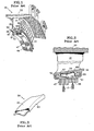
- Figure 1 is a perspective view of a conventional stator assembly;
- Figure 2 is a cross-sectional view of a section of a gas turbine engine using the stator assembly of Figure 1;
- Figure 3 is a perspective view of a damper from the stator assembly of Figure 1;
- Figure 4 is a cross-sectional view of a section of a gas turbine engine using another conventional stator assembly;
- Figure 5 is a perspective view of a damper from the stator assembly of Figure 4;
- Figure 6 is a cross-sectional view of a stator assembly in a gas turbine engine with one alternative embodiment of a damper of the present invention;
- Figure 7 is a perspective view of the damper of Figure 6;
- Figure 8 is a cross-sectional view of a stator assembly in a gas turbine engine with another embodiment of a damper of the present invention; and
- Figure 9 is a perspective view of the damper of Figure 8.
-
- Figures 1 and 2 display a
conventional stator assembly 30 used in the compressor section of a gas turbine engine. Theassembly 30 is a vane segment having a plurality ofvanes 31 extending between a radiallyouter platform 33 and a radiallyinner platform 35. Theassembly 30 is typically made by a casting or a brazement. A plurality of relief slits 37 in theinner platform 35 help reduce the build-up of stress caused by temperature gradients in thevanes 31 andplatforms - The
inner platform 35 includes anupstream flange 39 and adownstream flange 41. Theflanges channels inner air seal 47. Theinner air seal 47 comprises the seal land of a labyrinth seal assembly. Labyrinth seals prevent fluid leakage between a stationary component (e.g. stator assembly 30) and a rotating component (e.g. the compressor rotor). - The
seal land 47 includes an abradable material 49 (such as a metal honeycomb) mounted to asupport plate 51. Seal teeth T extend from the compressor rotor (not shown), face the abradable material and define a clearance therebetween. The clearance determines the effectiveness of the labyrinth seal. - The
support plate 51 includesopposed feet channels inner platform 35. When mounted together, theinner platform 35 and theinner air seal 47 define acavity 57. Anarcuate damper 59 resides in thecavity 57. An example of thisdamper 59 is part number 4319363 available from Pratt & Whitney of East Hartford, Connecticut - Figure 3 is a detailed view of the
damper 59. Thedamper 59 includesopposed arms central section 65. Thedamper 59 is formed from a sheet (not shown) of metal. At a first step, a forming die (not shown) folds thearms central section 65. At a second subsequent step, another forming die (not shown) bends the damper into an arcuate shape. - The
damper 59 requires compression for placement within thecavity 57. After insertion, this compression allows thedamper 59 to provide the appropriate amount of loading to theinner platform 35 and theinner air seal 47 for reducing vibration. As seen in Figure 2, thedamper 59 contacts theinner platform 35 at twolocations damper 59 contacts theinner air seal 47 at twolocations - One drawback of this
stator assembly 30 is the inability of thedamper 59 to apply equal loading applied to theinner platform 35 atlocations cavity 57 has a wedge shape. As seen in Figure 2, thecavity 57 enlarges in the downstream direction. This cavity shape requires thedamper 59 to have an asymmetric shape. The asymmetric shape of thedamper 59 produces unequal forces between thedamper 59 and the corresponding mating surfaces of theinner platform 35. Such unequal loading reduces the effectiveness of thedamper 59. For example, the unequal loading of thedamper 59 produces a torsional deformation in the vane when the vane vibrates in the flexing mode (relative to the engine circumferential direction). Similarly, the unequal loading of thedamper 59 produces a flexural deformation in the vane when the vane vibrates in a torsional mode. These deformations increase vane stresses. - Another drawback is the forming process that produces the
damper 59. When forming an asymmetric shape, the sheet metal tends to deform out of plane. The tooling used to form thedamper 59 must compensate for this tendency. This complicates tooling design and increases manufacturing costs. Additional manufacturing costs occasionally occur should thedamper 59 require straightening to correct such deformations. - Another drawback is the complex design of these dampers. Manufacturing tolerances prevent the manufacture of every damper to match the exact dimensions of every stator platform. To compensate for this possible mismatch and to allow the damper to comply evenly with the surfaces of the stator, the damper must have low stiffness in the circumferential direction. This helps reduce vibrational stresses equally over all vanes of the segment. Asymmetric dampers, however, introduce one additional level of complexity to this problem. Specifically,
asymmetric dampers 57 exhibit different bending stiffness (in the circumferential direction) at the fore and aft contact points 67, 69. - Figures 4 and 5 display another
conventional stator assembly 90. Similar to theaforementioned assembly 30, theassembly 90 includes a plurality ofvanes 91 extending between a radially outer platform (not shown) and a radiallyinner platform 93. Theinner platform 93 accepts aninner air seal 95. - An
arcuate damper 97 resides between theinner platform 93 and theinner air seal 95. An example of thisdamper 97 is part number 55H401 available from Pratt & Whiney of East Hartford, Connecticut. - Figure 5 is a detailed view of the
damper 97. Thedamper 97 includes opposedarms central section 103. Thedamper 97 is formed from a sheet of metal (not shown). At a first step, a forming die (not shown) folds thearms central section 103. At a second subsequent step, another forming die (not shown) bends the damper into an arcuate shape.Slots 105 help reduce the bending stiffness of thedamper 97, which permits more even distribution of load into each of theindividual vane platforms 35. - The
damper 97 requires compression for placement between theinner platform 93 and theinner air seal 95. After insertion, this compression allows thedamper 97 to provide the appropriate amount of loading to theinner platform 93 andinner air seal 95 for reducing vibration. As seen in Figure 4, thedamper 97 contacts theinner platform 93 at twolocations damper 97 also contacts theinner air seal 95 at twolocations 111, 113. - Similar to the
damper 57, thedamper 97 has several drawbacks. First, forming thedamper 97 requires multiple passes through the tooling equipment. - Second, the
damper 97 can function only in symmetric cavities. With symmetric cavities, dampers can provide equal damper loading to the contact points 107, 109. In order to use thedamper 97, the designer would have to modify the asymmetric cavity with additional structure to create a symmetric cavity. This, however, introduces unnecessary weight and cost to the engine. - Figures 6 and 7 display one alternative embodiment of a
stator assembly 150 of the present invention. The following description omits features of thestator assembly 150 previous described with respect toassemblies stator assembly 150 of the present invention includes a plurality ofvanes 151 extending between a radiallyouter platform 153 and a radiallyinner platform 155. Theassembly 150 is typically made by casting. - The
inner platform 155 accepts aninner air seal 157. Theinner air seal 157 comprises the seal land portion of a labyrinth seal assembly. The other portion of the labyrinth seal comprises seal teeth T on a rotating component (e.g. the compressor rotor). The labyrinth seal prevents fluid leakage between thestator assembly 150 and the rotor. The clearance between the teeth T and theinner air seal 157 determines the effectiveness of the labyrinth seal. - When mounted together, the
inner platform 155 and theinner air seal 157 define acavity 159. Due to the shape of the flowpath for core flow through the engine, thecavity 159 has a wedge shape. As seen in Figure 6, thecavity 159 enlarges in the downstream direction. Anarcuate damper 161 resides in thecavity 159. Figure 7 provides a detailed view of thedamper 161. - The
damper 161 includes opposedarms central section 167. Differently than with theaforementioned dampers damper 161 of the present invention can be formed in one pass through forming rolls (not shown) or a punch-press (not shown). The less complex shape of the damper 161 (compared todampers 59, 97) allows formation in one pass. In other words, the single pass through the forming rollspunch press createsbends damper 161. The forming rolls/punch press can also createslots 175 when forming thebends slots 175 could be provided to the sheet metal before passing through the forming rolls/punch press. - As with the earlier
conventional dampers damper 161 requires compression for placement within the cavity 15 9 and to create the required load for vibration damping. Referring back to Figure 6, thedamper 161 contacts theinner platform 155 and theinner air seal 157 at three locations. These contact locations correspond to thebends damper 161 contacts theplatform 155 at two points, thebends arms seal 157 at one point, thebend 171 on thecentral section 167. - Differently than with the
earlier dampers damper 161 can better compensate for unequal loading applied to theinner platform 155 at bends 169,173. Should unequal loading exist on thearms damper 161 will, in response, roll along the mating surface of theinner air seal 157 atbend 171 of thecentral section 167. Thedamper 161 will stop rolling along thebend 171 when the loading applied to the inner platform atbends - As seen in Figure 7, the
damper 161 has an asymmetric shape to accommodate the tapered shape of thecavity 159. The asymmetric design is more amenable to the adjustment of geometric attributes of thedamper 161 to produce the desired loads against theplatform 155. This configuration also more readily accommodates variation in the cavity between theplatform 155 and theseal 157 created during manufacture or by wear during engine operation. - Figures 8 and 9 display another alternative embodiment of the present invention, a
stator assembly 190. Thestator assembly 190 of the present invention includes a plurality ofvanes 191 extending between a radiallyouter platform 193 and a radiallyinner platform 195. Theassembly 190 is typically made by casting. - The
inner platform 195 accepts aninner air seal 197. Theinner air seal 197 faces seal teeth T on a rotating component (e.g. the compressor rotor) to define a labyrinth seal. The clearance between the teeth T and theinner air seal 197 determines the effectiveness of the labyrinth seal. When mounted together, theinner platform 195 and ininner air seal 197 defme acavity 199. As seen in Figure 8, thecavity 199 has a uniform size. An arcuate damper201 resides in thecavity 199. Figure 9 provides a detailed view of thedamper 201. - The
damper 201 has a different shape thandamper 161 in order to function properly incavity 199. Comparing Figures 6 and 8,damper 201 is shallower (in the radial direction) thandamper 161.Damper 201 is shallower since thecavity 199 is shallower thancavity 159. Since the cavity has a uniform size (i.e. no taper in the downstream direction), thedamper 201 is symmetric. - The
damper 201 includes opposedarms central section 207. Thedamper 201 is formed from a sheet of metal (not shown) in the same manner as described above withdamper 161. The forming process createsbends damper 201. The forming process can also createslots 215 when forming thebends slots 215 could be provided to the sheet metal before passing through the forming rolls/punch press. - The
damper 201 also requires compression for placement within thecavity 199 and to create the required load for vibration damping. Referring back to Figure 8, thedamper 201 contacts theinner platform 195 and theinner air seal 197 at three locations. These contact locations correspond to thebends damper 201 contacts theplatform 195 at two points, thebends arms seal 197 at one point, thebend 211 on thecentral section 207. - Differently than the aforementioned
conventional dampers damper 201 can better compensate for unequal loading applied to theinner platform 195 atbends arms damper 201 will, in response, roll along the mating surface of theinner air seal 197 atbend 211 of thecentral section 207. Thedamper 201 will stop rolling along thebend 211 when the loading applied to the inner platform atbends - As described above, the dampers of the present invention contact the inner platform of the stator at two locations and the seal at one location. The widely, and equally, spaced (about the vane axis) contact points provide sufficient contact force to resist torsion of the vane. If, however, damping vane torsional vibrations is not the prime concern, the dampers could be designed in an opposite arrangement (not shown) so that the damper contacts the inner platform of the stator at one location and the seal at two locations. Such an arrangement is useful, for example, in instances where stress caused by inner air seal vibration may be the prime concern.
- The present invention has been described in connection with the preferred embodiments of the various figures. It is to be understood that other similar embodiments may be used or modifications and additions may be made to the described embodiment for performing the same function of the present invention without deviating therefrom. Therefore, the present invention should not be limited to any single embodiment, but rather construed in breadth and scope in accordance with the recitation of the appended claims.
Claims (12)
- A stator assembly (150;190), comprising:wherein said medial section (167;207) engages one of said stator segment and said seal (157;197) and said opposed arms engage the other of said stator segment and said seal (157;197).a stator segment;a seal (157;197) mounted to said stator segment; anda damper (161;201) between said stator segment and said seal (157;197), said damper having:a medial section (167;207); andopposed arms (163,165;203,205) extending from said medial section (167;207);
- A damper (161;201) for reducing vibration between a stator segment and a seal (157;197), comprising:a medial section (167;207) for engaging one of said stator segment and said seal (157;197); andopposed arms (163,165;203,205) extending from said medial section (167;207) for engaging the other of said stator segment and said seal.
- The assembly or damper of claim 1 or 2, wherein said damper (201) is symmetric.
- The assembly or damper of claim 1 or 2, wherein said damper (161) is asymmetric.
- The assembly or damper of any preceding claim wherein said medial section (167;207) engages said seal (157;197).
- The assembly or damper of any preceding claim wherein said damper (161;201) further comprises a plurality of slots (175;215).
- A method of making a damper (161;201) for reducing vibration between a stator segment and a seal (157;197) , comprising the steps of:providing a sheet of material having a medial section (167;207) and opposed arms (163,165;203,205) extending from said medial section (167;207);forming a bend (171;211) at said medial section (167;207) so that said medial section (167;207) can engage one of said stator segment and said seal (157;197); andforming a bend (169,173;209,213) at each of said arms (163,165;203,205) so that said arms can engage the other of said stator segment and said seal (157;197).
- The method of claim 7, wherein said forming steps occur simultaneously.
- The method of claim 8, wherein said forming steps occur during a single pass through tooling equipment
- The method of any of claims 7 to 9, further comprising a step of providing a plurality of slots (175;215) to said damper (161;201).
- The method of any of claims 7 to 10, wherein said damper (201) is symmetric.
- The method of any of claims 7 to 10, wherein said damper (161) is asymmetric.
Applications Claiming Priority (2)
| Application Number | Priority Date | Filing Date | Title |
|---|---|---|---|
| US248532 | 1994-05-31 | ||
| US10/248,532 US7291946B2 (en) | 2003-01-27 | 2003-01-27 | Damper for stator assembly |
Publications (3)
| Publication Number | Publication Date |
|---|---|
| EP1441108A2 true EP1441108A2 (en) | 2004-07-28 |
| EP1441108A3 EP1441108A3 (en) | 2006-12-20 |
| EP1441108B1 EP1441108B1 (en) | 2011-03-02 |
Family
ID=32592788
Family Applications (1)
| Application Number | Title | Priority Date | Filing Date |
|---|---|---|---|
| EP04250425A Expired - Fee Related EP1441108B1 (en) | 2003-01-27 | 2004-01-27 | Damper for gas turbine stator assembly |
Country Status (3)
| Country | Link |
|---|---|
| US (1) | US7291946B2 (en) |
| EP (1) | EP1441108B1 (en) |
| DE (1) | DE602004031570D1 (en) |
Cited By (18)
| Publication number | Priority date | Publication date | Assignee | Title |
|---|---|---|---|---|
| WO2005078242A1 (en) * | 2004-02-11 | 2005-08-25 | Mtu Aero Engines Gmbh | Damping arrangement for guide vanes |
| EP2019188A1 (en) * | 2007-07-25 | 2009-01-28 | Siemens Aktiengesellschaft | Rotor stage with damping element |
| EP2048324A1 (en) * | 2007-10-11 | 2009-04-15 | Snecma | Turbine stator for aircraft turbomachine including a vibration damper device |
| CN102132047A (en) * | 2008-12-25 | 2011-07-20 | 三菱重工业株式会社 | Turbine blade and gas turbine |
| FR2971022A1 (en) * | 2011-02-02 | 2012-08-03 | Snecma | COMPRESSOR RECTIFIER STAGE FOR A TURBOMACHINE |
| WO2013115874A3 (en) * | 2011-11-11 | 2013-09-26 | United Technologies Corporation | Turbomachinery seal |
| EP2613021A3 (en) * | 2012-01-05 | 2013-11-13 | United Technologies Corporation | Stator vane spring damper |
| EP2696038A1 (en) * | 2012-08-07 | 2014-02-12 | MTU Aero Engines GmbH | Guide vane row for a turbomachine |
| EP2722487A1 (en) * | 2012-10-18 | 2014-04-23 | MTU Aero Engines GmbH | Form-fit housing component combination and method for its manufacture |
| EP2787180A1 (en) * | 2013-04-04 | 2014-10-08 | MTU Aero Engines GmbH | Guide blade assembly for a turbo engine |
| US8899914B2 (en) | 2012-01-05 | 2014-12-02 | United Technologies Corporation | Stator vane integrated attachment liner and spring damper |
| WO2014207058A1 (en) | 2013-06-28 | 2014-12-31 | Siemens Aktiengesellschaft | Sealing ring segment for a stator of a turbine |
| EP2811117A3 (en) * | 2013-06-05 | 2015-02-25 | Rolls-Royce Deutschland Ltd & Co KG | Shroud assembly for a turbo engine |
| FR3013759A1 (en) * | 2013-11-26 | 2015-05-29 | Snecma | BALANCING CROWN SECTOR, BALANCED TURBOMACHINE PART AND TURBOMACHINE |
| EP3073055A3 (en) * | 2015-03-24 | 2016-11-02 | United Technologies Corporation | Damper for stator assembly and stator assembly |
| EP3315728A1 (en) * | 2016-10-26 | 2018-05-02 | MTU Aero Engines GmbH | Gedämpfte leitschaufellagerung |
| EP3456975A1 (en) * | 2017-09-18 | 2019-03-20 | Thermodyn SAS | Rotating machine comprising a seal ring damping system |
| US11506382B2 (en) | 2019-09-12 | 2022-11-22 | General Electric Company | System and method for acoustic dampers with multiple volumes in a combustion chamber front panel |
Families Citing this family (35)
| Publication number | Priority date | Publication date | Assignee | Title |
|---|---|---|---|---|
| US7196438B2 (en) * | 2005-05-12 | 2007-03-27 | Emerson Electric Co. | Resilient isolation members and related methods of reducing acoustic noise and/or structural vibration in an electric machine |
| US7762761B2 (en) * | 2005-11-30 | 2010-07-27 | General Electric Company | Methods and apparatus for assembling turbine nozzles |
| DE102007009134A1 (en) * | 2007-02-24 | 2008-08-28 | Mtu Aero Engines Gmbh | Compressor of a gas turbine |
| US8038388B2 (en) * | 2007-03-05 | 2011-10-18 | United Technologies Corporation | Abradable component for a gas turbine engine |
| US8485785B2 (en) * | 2007-07-19 | 2013-07-16 | Siemens Energy, Inc. | Wear prevention spring for turbine blade |
| US8240120B2 (en) * | 2007-10-25 | 2012-08-14 | United Technologies Corporation | Vibration management for gas turbine engines |
| DE102008051544B4 (en) * | 2008-10-14 | 2012-12-27 | Continental Automotive Gmbh | Spindle drive with anti-rotation lock |
| US8087881B1 (en) | 2008-11-22 | 2012-01-03 | Florida Turbine Technologies, Inc. | Damped stator assembly |
| ES2382938T3 (en) * | 2009-02-05 | 2012-06-14 | Siemens Aktiengesellschaft | An annular vane assembly for a gas turbine engine |
| US8157507B1 (en) * | 2010-01-19 | 2012-04-17 | Florida Turbine Technologies, Inc. | Damped stator assembly |
| FR2961553B1 (en) * | 2010-06-18 | 2012-08-31 | Snecma | ANGULAR RECTIFIER SECTOR FOR TURBOMACHINE COMPRESSOR, TURBOMACHINE RECTIFIER AND TURBOMACHINE COMPRISING SUCH A SECTOR |
| FR2961554B1 (en) * | 2010-06-18 | 2012-07-20 | Snecma | ANGULAR RECTIFIER SECTOR FOR TURBOMACHINE COMPRESSOR, TURBOMACHINE RECTIFIER AND TURBOMACHINE COMPRISING SUCH A SECTOR |
| FR2962481B1 (en) * | 2010-07-12 | 2012-08-31 | Snecma Propulsion Solide | VIBRATION DAMPER WITH LEVER ARM FOR A ROTOR OF A GAS TURBINE ENGINE |
| US20130028713A1 (en) * | 2011-07-25 | 2013-01-31 | General Electric Company | Seal for turbomachine segments |
| US8926269B2 (en) * | 2011-09-06 | 2015-01-06 | General Electric Company | Stepped, conical honeycomb seal carrier |
| US8920116B2 (en) * | 2011-10-07 | 2014-12-30 | Siemens Energy, Inc. | Wear prevention system for securing compressor airfoils within a turbine engine |
| US20130134678A1 (en) * | 2011-11-29 | 2013-05-30 | General Electric Company | Shim seal assemblies and assembly methods for stationary components of rotary machines |
| FR2991372B1 (en) * | 2012-06-04 | 2014-05-16 | Snecma | TURBINE WHEEL IN A TURBOMACHINE |
| GB2525807B (en) * | 2013-02-05 | 2016-09-07 | Snecma | Flow distribution blading comprising an improved sealing plate |
| EP2881545B1 (en) * | 2013-12-04 | 2017-05-31 | MTU Aero Engines GmbH | Sealing element, sealing device and gas turbine engine |
| US20150260465A1 (en) * | 2014-03-17 | 2015-09-17 | Borgwarner Inc. | Retention device for a product |
| EP2937517B1 (en) * | 2014-04-24 | 2019-03-06 | Safran Aero Boosters SA | Stator of an axial turbomachine and corresponding turbomachine |
| WO2016022136A1 (en) | 2014-08-08 | 2016-02-11 | Siemens Energy, Inc. | Interstage seal housing optimization system in a gas turbine engine |
| US10221769B2 (en) | 2016-12-02 | 2019-03-05 | General Electric Company | System and apparatus for gas turbine combustor inner cap and extended resonating tubes |
| US10228138B2 (en) | 2016-12-02 | 2019-03-12 | General Electric Company | System and apparatus for gas turbine combustor inner cap and resonating tubes |
| US10220474B2 (en) | 2016-12-02 | 2019-03-05 | General Electricd Company | Method and apparatus for gas turbine combustor inner cap and high frequency acoustic dampers |
| KR101953462B1 (en) | 2017-05-24 | 2019-02-28 | 두산중공업 주식회사 | Vane assembly and gas turbine including vane assembly |
| US20210088144A1 (en) * | 2019-09-20 | 2021-03-25 | United Technologies Corporation | Self-centering seal and method of using same |
| FR3108675B1 (en) * | 2020-03-25 | 2022-11-04 | Safran Aircraft Engines | Turbomachine stator distributor comprising a continuous and free sealing ring |
| US11156110B1 (en) | 2020-08-04 | 2021-10-26 | General Electric Company | Rotor assembly for a turbine section of a gas turbine engine |
| US11572794B2 (en) * | 2021-01-07 | 2023-02-07 | General Electric Company | Inner shroud damper for vibration reduction |
| CN114810221B (en) * | 2021-01-27 | 2023-09-15 | 中国航发上海商用航空发动机制造有限责任公司 | Stator blade and inner ring supporting mechanism |
| JP7465374B2 (en) | 2021-02-05 | 2024-04-10 | 三菱重工業株式会社 | Stator blade ring and rotating machine |
| US11655719B2 (en) | 2021-04-16 | 2023-05-23 | General Electric Company | Airfoil assembly |
| CN113898421A (en) * | 2021-10-10 | 2022-01-07 | 中国航发沈阳发动机研究所 | Compressor stator inner ring and rotor stator sealing connection structure thereof |
Citations (8)
| Publication number | Priority date | Publication date | Assignee | Title |
|---|---|---|---|---|
| US3966356A (en) * | 1975-09-22 | 1976-06-29 | General Motors Corporation | Blade tip seal mount |
| US4242042A (en) * | 1978-05-16 | 1980-12-30 | United Technologies Corporation | Temperature control of engine case for clearance control |
| GB2219355A (en) * | 1988-06-02 | 1989-12-06 | United Technologies Corp | Stator vane assembly seal and anti-vibration arrangement |
| EP0451013A1 (en) * | 1990-04-03 | 1991-10-09 | Sollac | Method and apparatus for making an embossed part in a sheet metal plate and product obtained by this method |
| EP0616110A1 (en) * | 1993-03-03 | 1994-09-21 | Societe Nationale D'etude Et De Construction De Moteurs D'aviation "Snecma" | Row of blades unsupported at one end |
| US5462403A (en) * | 1994-03-21 | 1995-10-31 | United Technologies Corporation | Compressor stator vane assembly |
| DE4442795A1 (en) * | 1994-12-01 | 1996-06-05 | Teves Gmbh Alfred | Anti=rattle spring for brake discs |
| GB2298680A (en) * | 1995-03-06 | 1996-09-11 | Mtu Muenchen Gmbh | Stator vane seal support |
Family Cites Families (19)
| Publication number | Priority date | Publication date | Assignee | Title |
|---|---|---|---|---|
| US2991045A (en) * | 1958-07-10 | 1961-07-04 | Westinghouse Electric Corp | Sealing arrangement for a divided tubular casing |
| US3326523A (en) * | 1965-12-06 | 1967-06-20 | Gen Electric | Stator vane assembly having composite sectors |
| US3601414A (en) * | 1969-10-29 | 1971-08-24 | Ford Motor Co | Ceramic crossarm seal for gas turbine regenerators |
| US3730640A (en) * | 1971-06-28 | 1973-05-01 | United Aircraft Corp | Seal ring for gas turbine |
| US3887299A (en) * | 1973-08-28 | 1975-06-03 | Us Air Force | Non-abradable turbine seal |
| US4053254A (en) * | 1976-03-26 | 1977-10-11 | United Technologies Corporation | Turbine case cooling system |
| US4314792A (en) * | 1978-12-20 | 1982-02-09 | United Technologies Corporation | Turbine seal and vane damper |
| US4537024A (en) * | 1979-04-23 | 1985-08-27 | Solar Turbines, Incorporated | Turbine engines |
| US4285633A (en) * | 1979-10-26 | 1981-08-25 | The United States Of America As Represented By The Secretary Of The Air Force | Broad spectrum vibration damper assembly fixed stator vanes of axial flow compressor |
| US4621976A (en) * | 1985-04-23 | 1986-11-11 | United Technologies Corporation | Integrally cast vane and shroud stator with damper |
| US5354072A (en) * | 1989-12-19 | 1994-10-11 | Specialist Sealing Limited | Hollow metal sealing rings |
| US5215432A (en) * | 1991-07-11 | 1993-06-01 | United Technologies Corporation | Stator vane damper |
| US5346362A (en) * | 1993-04-26 | 1994-09-13 | United Technologies Corporation | Mechanical damper |
| US5927942A (en) * | 1993-10-27 | 1999-07-27 | United Technologies Corporation | Mounting and sealing arrangement for a turbine shroud segment |
| US5681142A (en) * | 1993-12-20 | 1997-10-28 | United Technologies Corporation | Damping means for a stator assembly of a gas turbine engine |
| US5827047A (en) * | 1996-06-27 | 1998-10-27 | United Technologies Corporation | Turbine blade damper and seal |
| GB2344383B (en) * | 1998-12-01 | 2002-06-26 | Rolls Royce Plc | A bladed rotor |
| US6139264A (en) * | 1998-12-07 | 2000-10-31 | General Electric Company | Compressor interstage seal |
| GB0108398D0 (en) * | 2001-04-04 | 2001-05-23 | Siemens Ag | Seal element for sealing a gap and combustion turbine having a seal element |
-
2003
- 2003-01-27 US US10/248,532 patent/US7291946B2/en not_active Expired - Lifetime
-
2004
- 2004-01-27 DE DE602004031570T patent/DE602004031570D1/en not_active Expired - Lifetime
- 2004-01-27 EP EP04250425A patent/EP1441108B1/en not_active Expired - Fee Related
Patent Citations (8)
| Publication number | Priority date | Publication date | Assignee | Title |
|---|---|---|---|---|
| US3966356A (en) * | 1975-09-22 | 1976-06-29 | General Motors Corporation | Blade tip seal mount |
| US4242042A (en) * | 1978-05-16 | 1980-12-30 | United Technologies Corporation | Temperature control of engine case for clearance control |
| GB2219355A (en) * | 1988-06-02 | 1989-12-06 | United Technologies Corp | Stator vane assembly seal and anti-vibration arrangement |
| EP0451013A1 (en) * | 1990-04-03 | 1991-10-09 | Sollac | Method and apparatus for making an embossed part in a sheet metal plate and product obtained by this method |
| EP0616110A1 (en) * | 1993-03-03 | 1994-09-21 | Societe Nationale D'etude Et De Construction De Moteurs D'aviation "Snecma" | Row of blades unsupported at one end |
| US5462403A (en) * | 1994-03-21 | 1995-10-31 | United Technologies Corporation | Compressor stator vane assembly |
| DE4442795A1 (en) * | 1994-12-01 | 1996-06-05 | Teves Gmbh Alfred | Anti=rattle spring for brake discs |
| GB2298680A (en) * | 1995-03-06 | 1996-09-11 | Mtu Muenchen Gmbh | Stator vane seal support |
Cited By (37)
| Publication number | Priority date | Publication date | Assignee | Title |
|---|---|---|---|---|
| US8105016B2 (en) | 2004-02-11 | 2012-01-31 | Mtu Aero Engines Gmbh | Damping arrangement for guide vanes |
| WO2005078242A1 (en) * | 2004-02-11 | 2005-08-25 | Mtu Aero Engines Gmbh | Damping arrangement for guide vanes |
| EP2019188A1 (en) * | 2007-07-25 | 2009-01-28 | Siemens Aktiengesellschaft | Rotor stage with damping element |
| FR2922263A1 (en) * | 2007-10-11 | 2009-04-17 | Snecma Sa | TURBINE STATOR FOR AN AIRCRAFT TURBINE ENGINE INCORPORATING A VIBRATION DAMPING DEVICE |
| US8133010B2 (en) | 2007-10-11 | 2012-03-13 | Snecma | Turbine stator for aircraft turbine engine including a vibration damping device |
| RU2474697C2 (en) * | 2007-10-11 | 2013-02-10 | Снекма | Aircraft gas turbine engine turbine stator with vibration damper |
| EP2048324A1 (en) * | 2007-10-11 | 2009-04-15 | Snecma | Turbine stator for aircraft turbomachine including a vibration damper device |
| CN102132047A (en) * | 2008-12-25 | 2011-07-20 | 三菱重工业株式会社 | Turbine blade and gas turbine |
| EP2372165A1 (en) * | 2008-12-25 | 2011-10-05 | Mitsubishi Heavy Industries, Ltd. | Turbine blade and gas turbine |
| US8708641B2 (en) | 2008-12-25 | 2014-04-29 | Mitsubishi Heavy Industries, Ltd. | Turbine blade and gas turbine |
| EP2372165A4 (en) * | 2008-12-25 | 2012-06-06 | Mitsubishi Heavy Ind Ltd | Turbine blade and gas turbine |
| CN102132047B (en) * | 2008-12-25 | 2014-11-05 | 三菱重工业株式会社 | Turbine blade and gas turbine |
| FR2971022A1 (en) * | 2011-02-02 | 2012-08-03 | Snecma | COMPRESSOR RECTIFIER STAGE FOR A TURBOMACHINE |
| US9644640B2 (en) | 2011-02-02 | 2017-05-09 | Snecma | Compressor nozzle stage for a turbine engine |
| WO2013115874A3 (en) * | 2011-11-11 | 2013-09-26 | United Technologies Corporation | Turbomachinery seal |
| US8899914B2 (en) | 2012-01-05 | 2014-12-02 | United Technologies Corporation | Stator vane integrated attachment liner and spring damper |
| US8920112B2 (en) | 2012-01-05 | 2014-12-30 | United Technologies Corporation | Stator vane spring damper |
| EP2613021A3 (en) * | 2012-01-05 | 2013-11-13 | United Technologies Corporation | Stator vane spring damper |
| EP2696038A1 (en) * | 2012-08-07 | 2014-02-12 | MTU Aero Engines GmbH | Guide vane row for a turbomachine |
| EP2722487A1 (en) * | 2012-10-18 | 2014-04-23 | MTU Aero Engines GmbH | Form-fit housing component combination and method for its manufacture |
| EP2787180A1 (en) * | 2013-04-04 | 2014-10-08 | MTU Aero Engines GmbH | Guide blade assembly for a turbo engine |
| EP2811117A3 (en) * | 2013-06-05 | 2015-02-25 | Rolls-Royce Deutschland Ltd & Co KG | Shroud assembly for a turbo engine |
| US10215041B2 (en) | 2013-06-28 | 2019-02-26 | Siemens Aktiengesellschaft | Sealing ring segment for a stator of a turbine |
| EP2818642A1 (en) * | 2013-06-28 | 2014-12-31 | Siemens Aktiengesellschaft | Seal ring segment for a stator of a turbine |
| WO2014207058A1 (en) | 2013-06-28 | 2014-12-31 | Siemens Aktiengesellschaft | Sealing ring segment for a stator of a turbine |
| CN105392966A (en) * | 2013-06-28 | 2016-03-09 | 西门子股份公司 | Sealing ring segment for a stator of a turbine |
| CN105392966B (en) * | 2013-06-28 | 2018-03-20 | 西门子股份公司 | Sealing ring segment for the stator of turbine |
| CN105793523A (en) * | 2013-11-26 | 2016-07-20 | 斯奈克玛 | Balanced turbine engine portion and turbine engine |
| FR3013759A1 (en) * | 2013-11-26 | 2015-05-29 | Snecma | BALANCING CROWN SECTOR, BALANCED TURBOMACHINE PART AND TURBOMACHINE |
| WO2015079150A1 (en) * | 2013-11-26 | 2015-06-04 | Snecma | Balanced turbine engine portion and turbine engine |
| CN105793523B (en) * | 2013-11-26 | 2019-03-01 | 斯奈克玛 | Balanced type turbine engine portion and turbogenerator |
| US10415424B2 (en) | 2013-11-26 | 2019-09-17 | Safran Aircraft Engines | Balanced turbine engine portion and turbine engine |
| EP3073055A3 (en) * | 2015-03-24 | 2016-11-02 | United Technologies Corporation | Damper for stator assembly and stator assembly |
| EP3315728A1 (en) * | 2016-10-26 | 2018-05-02 | MTU Aero Engines GmbH | Gedämpfte leitschaufellagerung |
| EP3456975A1 (en) * | 2017-09-18 | 2019-03-20 | Thermodyn SAS | Rotating machine comprising a seal ring damping system |
| FR3071281A1 (en) * | 2017-09-18 | 2019-03-22 | Thermodyn | ROTATING MACHINE COMPRISING A DAMPING SYSTEM OF A SEAL |
| US11506382B2 (en) | 2019-09-12 | 2022-11-22 | General Electric Company | System and method for acoustic dampers with multiple volumes in a combustion chamber front panel |
Also Published As
| Publication number | Publication date |
|---|---|
| DE602004031570D1 (en) | 2011-04-14 |
| US7291946B2 (en) | 2007-11-06 |
| EP1441108A3 (en) | 2006-12-20 |
| EP1441108B1 (en) | 2011-03-02 |
| US20040145251A1 (en) | 2004-07-29 |
Similar Documents
| Publication | Publication Date | Title |
|---|---|---|
| US7291946B2 (en) | Damper for stator assembly | |
| EP1408198B1 (en) | Assembly type nozzle diaphragm and method of assembling the same | |
| EP2072184B1 (en) | Jig and method for processing cylinder block | |
| US7618234B2 (en) | Hook ring segment for a compressor vane | |
| CN108691569B (en) | Device for cooling a turbomachine rotor | |
| JPH06105050B2 (en) | How to make an interference fit and interference fit hanger | |
| KR100192115B1 (en) | Interstage casing for a pump made of sheet metal and method of manufacturing the same | |
| US7114927B2 (en) | Fixing method for the blading of a fluid-flow machine and fixing arrangement | |
| CN106194987A (en) | Thrust bearing assembl | |
| US10240474B2 (en) | Turbomachine having a seal device | |
| US20080170939A1 (en) | Diaphragm for Turbomachines and Method of Manufacture | |
| US20090304503A1 (en) | Stator blade segment of a thermal turbomachine, associated production method and also thermal turbomachine | |
| WO2008084038A1 (en) | Diaphragm for turbomachines and method of manufacture | |
| US9003852B2 (en) | Sheet metal blank | |
| US9664054B2 (en) | Turbomachine rotor with blade roots with adjusting protrusions | |
| JP5965622B2 (en) | Steam turbine singlet joint for margin stage nozzle with pinned or bolted inner ring | |
| JP3518214B2 (en) | Selective mounting method of bearing metal | |
| JP4436273B2 (en) | Turbine partition plate and turbine provided with the same | |
| CN217270344U (en) | Moving blade shroud for regulating stage of industrial steam turbine | |
| US9068475B2 (en) | Stator vane assembly | |
| EP2055897A1 (en) | Flexible Shims | |
| JP3682131B2 (en) | Turbine blade and its assembly method | |
| EP1433926A2 (en) | Seal apparatus | |
| US7908849B2 (en) | Bladed shell or stator shell for a hydrodynamic torque converter, method for producing a stator shell of said type, and hydrodynamic torque converter having a stator shell of said type | |
| US7837444B2 (en) | Vane arrangement and a method of making vane arrangement |
Legal Events
| Date | Code | Title | Description |
|---|---|---|---|
| PUAI | Public reference made under article 153(3) epc to a published international application that has entered the european phase |
Free format text: ORIGINAL CODE: 0009012 |
|
| AK | Designated contracting states |
Kind code of ref document: A2 Designated state(s): AT BE BG CH CY CZ DE DK EE ES FI FR GB GR HU IE IT LI LU MC NL PT RO SE SI SK TR |
|
| AX | Request for extension of the european patent |
Extension state: AL LT LV MK |
|
| PUAL | Search report despatched |
Free format text: ORIGINAL CODE: 0009013 |
|
| AK | Designated contracting states |
Kind code of ref document: A3 Designated state(s): AT BE BG CH CY CZ DE DK EE ES FI FR GB GR HU IE IT LI LU MC NL PT RO SE SI SK TR |
|
| AX | Request for extension of the european patent |
Extension state: AL LT LV MK |
|
| 17P | Request for examination filed |
Effective date: 20070613 |
|
| AKX | Designation fees paid |
Designated state(s): DE FR GB |
|
| 17Q | First examination report despatched |
Effective date: 20070802 |
|
| GRAP | Despatch of communication of intention to grant a patent |
Free format text: ORIGINAL CODE: EPIDOSNIGR1 |
|
| GRAS | Grant fee paid |
Free format text: ORIGINAL CODE: EPIDOSNIGR3 |
|
| GRAA | (expected) grant |
Free format text: ORIGINAL CODE: 0009210 |
|
| AK | Designated contracting states |
Kind code of ref document: B1 Designated state(s): DE FR GB |
|
| REG | Reference to a national code |
Ref country code: GB Ref legal event code: FG4D |
|
| REF | Corresponds to: |
Ref document number: 602004031570 Country of ref document: DE Date of ref document: 20110414 Kind code of ref document: P |
|
| REG | Reference to a national code |
Ref country code: DE Ref legal event code: R096 Ref document number: 602004031570 Country of ref document: DE Effective date: 20110414 |
|
| PLBE | No opposition filed within time limit |
Free format text: ORIGINAL CODE: 0009261 |
|
| STAA | Information on the status of an ep patent application or granted ep patent |
Free format text: STATUS: NO OPPOSITION FILED WITHIN TIME LIMIT |
|
| 26N | No opposition filed |
Effective date: 20111205 |
|
| REG | Reference to a national code |
Ref country code: DE Ref legal event code: R097 Ref document number: 602004031570 Country of ref document: DE Effective date: 20111205 |
|
| REG | Reference to a national code |
Ref country code: FR Ref legal event code: ST Effective date: 20120928 |
|
| PG25 | Lapsed in a contracting state [announced via postgrant information from national office to epo] |
Ref country code: FR Free format text: LAPSE BECAUSE OF NON-PAYMENT OF DUE FEES Effective date: 20120131 |
|
| PGFP | Annual fee paid to national office [announced via postgrant information from national office to epo] |
Ref country code: GB Payment date: 20130123 Year of fee payment: 10 Ref country code: DE Payment date: 20130123 Year of fee payment: 10 |
|
| REG | Reference to a national code |
Ref country code: DE Ref legal event code: R119 Ref document number: 602004031570 Country of ref document: DE |
|
| GBPC | Gb: european patent ceased through non-payment of renewal fee |
Effective date: 20140127 |
|
| REG | Reference to a national code |
Ref country code: DE Ref legal event code: R119 Ref document number: 602004031570 Country of ref document: DE Effective date: 20140801 |
|
| PG25 | Lapsed in a contracting state [announced via postgrant information from national office to epo] |
Ref country code: DE Free format text: LAPSE BECAUSE OF NON-PAYMENT OF DUE FEES Effective date: 20140801 |
|
| PG25 | Lapsed in a contracting state [announced via postgrant information from national office to epo] |
Ref country code: GB Free format text: LAPSE BECAUSE OF NON-PAYMENT OF DUE FEES Effective date: 20140127 |