EP1440771A1 - Controlling device for a hand-held power tool - Google Patents
Controlling device for a hand-held power tool Download PDFInfo
- Publication number
- EP1440771A1 EP1440771A1 EP04100156A EP04100156A EP1440771A1 EP 1440771 A1 EP1440771 A1 EP 1440771A1 EP 04100156 A EP04100156 A EP 04100156A EP 04100156 A EP04100156 A EP 04100156A EP 1440771 A1 EP1440771 A1 EP 1440771A1
- Authority
- EP
- European Patent Office
- Prior art keywords
- sensor
- handle
- hand
- control
- force
- Prior art date
- Legal status (The legal status is an assumption and is not a legal conclusion. Google has not performed a legal analysis and makes no representation as to the accuracy of the status listed.)
- Granted
Links
Images


Classifications
-
- H—ELECTRICITY
- H03—ELECTRONIC CIRCUITRY
- H03K—PULSE TECHNIQUE
- H03K17/00—Electronic switching or gating, i.e. not by contact-making and –breaking
- H03K17/94—Electronic switching or gating, i.e. not by contact-making and –breaking characterised by the way in which the control signals are generated
- H03K17/96—Touch switches
-
- B—PERFORMING OPERATIONS; TRANSPORTING
- B25—HAND TOOLS; PORTABLE POWER-DRIVEN TOOLS; MANIPULATORS
- B25F—COMBINATION OR MULTI-PURPOSE TOOLS NOT OTHERWISE PROVIDED FOR; DETAILS OR COMPONENTS OF PORTABLE POWER-DRIVEN TOOLS NOT PARTICULARLY RELATED TO THE OPERATIONS PERFORMED AND NOT OTHERWISE PROVIDED FOR
- B25F5/00—Details or components of portable power-driven tools not particularly related to the operations performed and not otherwise provided for
-
- H—ELECTRICITY
- H01—ELECTRIC ELEMENTS
- H01H—ELECTRIC SWITCHES; RELAYS; SELECTORS; EMERGENCY PROTECTIVE DEVICES
- H01H9/00—Details of switching devices, not covered by groups H01H1/00 - H01H7/00
- H01H9/02—Bases, casings, or covers
- H01H9/06—Casing of switch constituted by a handle serving a purpose other than the actuation of the switch, e.g. by the handle of a vacuum cleaner
Definitions
- the invention relates to a control of a hand tool, in particular one Chisel hammer or hammer drill.
- Hand tool machines experience an interaction when used appropriately with the workpiece to be machined, resulting in the handheld machine tools stochastic acceleration forces act to guide over at least one Guide handle can be actively compensated by the user via the hand-arm system have to.
- handheld machine tools have a monostable, at which Appropriate use constantly operated by the user, main or Control switch, which is usually on the workpiece on one hand, Guide handle is arranged.
- main or Control switch which is usually on the workpiece on one hand
- Guide handle is arranged. This makes a sufficient ergonomic Safety in use achieved by controlling the handheld power tool Guide handle must at least be included and thus intuitively held by the user becomes.
- the one on the comprehensive guide handle is on the workpiece side arranged main or control switch designed as a force sensor, which via a Microcontroller that controls the hand tool.
- a hand tool has a handle on the comprehensive Force sensor for measuring the contact pressure on the user side, via a Microcontroller-controlled actuator on the handle to reduce its vibrations. After DE4306524 the hand tool is dependent on the contact pressure on the Workpiece controlled.
- a handheld machine tool is the most comprehensive Guide handle has a force sensor that can be actuated by the thumb only on the transverse side arranged, which via a microcontroller with different control algorithms intuitively controls the hand tool. At least in the control algorithms which Not constantly needing thumb thumb pressure is one for safe use the necessary gripping of the guide handle is not ergonomically ensured.
- the object of the invention is to implement control of a Hand machine tool with increased safety of use.
- a handheld machine tool essentially has a drive for a tool Control means for controlling a drive means and a manual one Handle with a sensor connected to the control means with a manual actuatable first sensor surface, at least one second sensor surface being present and both sensor surfaces within a manually graspable grip area are circumferentially offset.
- sensor areas is sufficient for a sufficient Reliability of use necessary to grip the handle ergonomically from the control means detectable and the drive can be activated / deactivated accordingly.
- the handle, the guide handle and / or a side handle is advantageous, whereby a necessary enclosure can be detected individually or in combination, for example in Depending on the operating mode when chiseling only the guide handle, when Impact drilling of the guide handle and the side handle.
- the sensor advantageously has an internal switching threshold value, which means that one incomplete but sufficient touch is reliably detectable.
- the sensor advantageously has an internal sensor circuit with a logic output, whereby this digitally designed the control means designed as a microcontroller with a circuit breaker can control.
- At least two sensors advantageously have logic outputs which are connected to one another are logically AND linked, which results in a safety signal from the individual sensor values with regard to a minimum grip of the handle can be generated.
- a False signal generated by one-sided contamination of the handle suppressed.
- the sensor is advantageous as a differential force sensor with respect to the handle along the Working direction designed, for example.
- a polymer film force sensor between one tool-side and a user-side grip surface which means that when encircling the The necessary hand force can be reliably detected as a surround signal is.
- the differential force sensor consisting of two oppositely oriented and interconnected force sensors formed, for example. Piezo sensors, which each against measure a core of the handle rigidly connected to the hand-held power tool, whereby at least partially existing force sensors additionally for the Differential force sensor can be used to detect the encircling signal.
- the two force sensors each advantageously have an internal sensor circuit with one at least quasi-continuous output, whereby the two measured Absolute force values of the tool-side and user-side gripping surfaces as such and in suitable function, for example as a difference and sum, the control means for control Are available.
- the senor is advantageously a contact sensor with contact surfaces trained sensor surfaces, which works on the principle of a high-resistance Resistance sensor or capacitive sensor with two isolated from each other Touch pads work, causing a hand or a touch Hand protection that bridges both contact surfaces, reliable as Enclosure signal is detectable.
- the contact contact surfaces are advantageously designed as conductive sheets, which in one Handle material acting as an insulator are embedded, which means that even in the harsh environment of the Construction reliable sensor is realizable.
- a plurality of sensor surfaces are advantageous, at least in part circumferentially, in pairs alternating sensor surfaces connected to each other, making two partially circumferential nested touch contact surfaces are formed, the flat Form structures, e.g. combs, serpentines or spirals.
- Exactly two at least two sensors are advantageous in each case from a plurality of sensor surfaces assigned, whereby the grasping of the handle is segmentally detectable is.
- the handheld power tool is a sensor signal from a sensor Control parameters recorded and in a second step depending on the control parameter controlled by the control means of the drive, the first step with the sensor manual grasping of a grip area is detected.
- the advantage in the second step is when a minimum differential force is exceeded and thus detected sufficient grip of the handle the sensor control for the drive activated or otherwise deactivated.
- the drive is activated in the second step, it is further advantageous in a third If the user exceeds a minimum total force, the drive is activated in Depending on this force, the drive power is regulated and if one is exceeded the tool-side minimum total force of the drive is deactivated, creating an intuitive Power control of the hand tool is carried out.
- a preselectable operating mode is advantageous Control parameters, which further advantageous when chiseling only a minimum differential force of the guide handle for an activated sensor control is necessary when Impact drilling, however, each have a minimum differential force between the guide handle and the Side handle.
- the time is a further control parameter, which makes it advantageous advantageous by briefly pressing or pulling the handheld power tool off the drive is activated or deactivated.
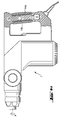
- a handheld power tool 1 for rotating and striking drive of a tool, not shown, along a working direction A
- a control means 2 for Control of a drive means 3 in the form of an electric motor.
- Two by hand comprehensive handles 4a, 4b in the form of a guide handle and a side handle each have two sensors 5a, 5b connected to the control means 2 with four manually actuatable sensor surfaces 6a, 6b, 6c, 6d. These are manual within one comprehensive handle area X arranged circumferentially offset.
- the sensors 5a, 5b are as Touch sensors with sensor surfaces 6a designed as touch contact surfaces 7, 6b, 6c, 6d.
- the touch contact surfaces 7 are as conductive sheets formed, which are embedded in the handles 4a, 4b made of plastic.
- touch contact surfaces 7 form one over the Circumference U circumferentially developed from flat structures, according to Fig. 2a combs, according to Fig. 2b serpentines or according to Fig. 2c spirals. Are each circumferentially in pairs alternating contact contact surfaces 7a, 7b with each other connected.
- the sensor surfaces 6a, 6c and 6b, 6d lying in pairs form each with two parts of an integrated sensor circuit 8 offset circumferentially by 90 ° Sensors 5a, 5b.
- This integrated sensor circuit 8 has one Threshold switch 9 and a logic output 10 on.
- the two sensors 5a, 5b associated logic outputs 10 are in a NAND circuit 11 with each other logically AND linked.
- the sensor 5 is in a variant of the handle 4a as along the Working direction
- a sensitive differential force sensor 13 in the form of a polymer film force sensor formed by between a tool-side gripping surface 14a and a user-side gripping surface 14b is arranged.
- Fig. 4b is another Variant of the differential force sensor 13 from two individual, opposite to each other oriented and connected, force sensors 15a, 15b in the form of two piezo sensors trained, each stiff against one with the hand tool 1 connected core 16 of the handle 4a are sensitive.
- the two force sensors 15a, 15b each have an internal sensor circuit 8 'with an at least quasi-continuous output 10', which is provided with a sum / difference circuit 17 for determining the difference force ⁇ F and the sum force ⁇ F are connected, which are brought into relation to one another in the control means 2 with a time t, a time span ⁇ t, a minimum differential force ⁇ F min or a minimum total force ⁇ F min .
Landscapes
- Engineering & Computer Science (AREA)
- Mechanical Engineering (AREA)
- Percussive Tools And Related Accessories (AREA)
- Manipulator (AREA)
Abstract
Description
Die Erfindung bezeichnet eine Steuerung einer Handwerkzeugmaschine, insbesondere eines Meisselhammers oder Bohrhammers.The invention relates to a control of a hand tool, in particular one Chisel hammer or hammer drill.
Handwerkzeugmaschinen erfahren bei zweckentsprechender Nutzung eine Wechselwirkung mit dem zu bearbeitenden Werkstück, wodurch auf die Handwerkzeugmaschinen stochastische Beschleunigungskräfte wirken, die zur Führung über zumindest einen Führungshandgriff über das Hand-Arm-System vom Nutzer aktiv kompensiert werden müssen.Hand tool machines experience an interaction when used appropriately with the workpiece to be machined, resulting in the handheld machine tools stochastic acceleration forces act to guide over at least one Guide handle can be actively compensated by the user via the hand-arm system have to.
Üblicherweise haben Handwerkzeugmaschinen einen monostabilen, bei der zweckentsprechenden Nutzung ständig vom Nutzer manuell zu betätigenden, Haupt- oder Regelschalter, welcher zumeist werkstückseitig an einem, mit einer Hand umfassbaren, Führungshandgriff angeordnet ist. Dadurch wird ergonomisch eine hinreichende Nutzungssicherheit erreicht, indem bei der Steuerung der Handwerkzeugmaschine der Führungshandgriff zumindest umfasst sein muss und somit vom Nutzer intuitiv fest gehalten wird.Typically, handheld machine tools have a monostable, at which Appropriate use constantly operated by the user, main or Control switch, which is usually on the workpiece on one hand, Guide handle is arranged. This makes a sufficient ergonomic Safety in use achieved by controlling the handheld power tool Guide handle must at least be included and thus intuitively held by the user becomes.
Da insbesondere bei monotonen Bearbeitungsvorgängen eine ständige Betätigung des Haupt- oder Regelschalters lästig ist, sind oftmals zusätzliche Arretierungsmittel vorhanden, welche bei bestimmten Betriebsmodi mit geringeren Anforderungen für eine hinreichende Nutzungssicherheit, bspw. Meisseln, eine Arretierung des Haupt- oder Regelschalters in Arbeitsstellung gestatten sowie durch Betätigung des Haupt- oder Regelschalters intuitiv lösbar sind.Since a constant actuation of the Main or control switch is annoying, additional locking means are often available, which in certain operating modes with lower requirements for a sufficient Safety in use, for example chisels, a locking of the main or control switch in Allow working position and intuitively by operating the main or control switch are solvable.
Nach der US5014793 ist der am umfassbaren Führungshandgriff werkstückseitig angeordnete Haupt- oder Regelschalter als Kraftsensor ausgebildet, welcher über einen Mikrocontroller die Handwerkzeugmaschine steuert.According to US5014793, the one on the comprehensive guide handle is on the workpiece side arranged main or control switch designed as a force sensor, which via a Microcontroller that controls the hand tool.
Nach der EP1221359 weist eine Handwerkzeugmaschine am umfassbaren Handgriff einen Kraftsensor zur Messung des nutzerseitigen Anpressdrucks auf, um über einen vom Mikrocontroller gesteuerten Aktor am Handgriff dessen Vibrationen zu vermindern. Nach der DE4306524 wird die Handwerkzeugmaschine in Abhängigkeit vom Anpressdruck auf das Werkstück gesteuert.According to EP1221359, a hand tool has a handle on the comprehensive Force sensor for measuring the contact pressure on the user side, via a Microcontroller-controlled actuator on the handle to reduce its vibrations. After DE4306524 the hand tool is dependent on the contact pressure on the Workpiece controlled.
Nach der DE19738092 ist bei einer Handwerkzeugmaschine am umfassbaren Führungshandgriff ausschliesslich querseitig ein vom Daumen betätigbarer Kraftsensor angeordnet, welcher über einen Mikrocontroller mit unterschiedlichen Steueralgorithmen intuitiv die Handwerkzeugmaschine steuert. Zumindest in den Steueralgorithmen, welche nicht ständig den Steuerdruck des Daumens benötigen, ist eine zur sicheren Nutzung notwendige Umfassung des Führungshandgriffs nicht ergonomisch sichergestellt.According to DE19738092, a handheld machine tool is the most comprehensive Guide handle has a force sensor that can be actuated by the thumb only on the transverse side arranged, which via a microcontroller with different control algorithms intuitively controls the hand tool. At least in the control algorithms which Not constantly needing thumb thumb pressure is one for safe use the necessary gripping of the guide handle is not ergonomically ensured.
Die Aufgabe der Erfindung besteht in der Realisierung einer Steuerung einer Handwerkzeugmaschine mit erhöhter Nutzungssicherheit.The object of the invention is to implement control of a Hand machine tool with increased safety of use.
Die Aufgabe wird im Wesentlichen durch die Merkmale der unabhängigen Ansprüche gelöst. Vorteilhafte Weiterbildungen ergeben sich aus den Unteransprüchen.The task is essentially solved by the features of the independent claims. Advantageous further developments result from the subclaims.
Im Wesentlichen weist eine Handwerkzeugmaschine zum Antrieb eines Werkzeugs ein Steuermittel zur Steuerung eines Antriebsmittels sowie einen händisch umfassbaren Handgriff mit einem, mit dem Steuermittel verbundenen, Sensor mit einer manuell betätigbaren ersten Sensorfläche auf, wobei zumindest eine zweite Sensorfläche vorhanden ist und beide Sensorflächen innerhalb eines händisch umfassbaren Griffbereiches umfänglich versetzt angeordnet sind.A handheld machine tool essentially has a drive for a tool Control means for controlling a drive means and a manual one Handle with a sensor connected to the control means with a manual actuatable first sensor surface, at least one second sensor surface being present and both sensor surfaces within a manually graspable grip area are circumferentially offset.
Durch die zumindest beiden, innerhalb eines händisch umfassbaren Griffbereiches umfänglich versetzt angeordneten, Sensorflächen ist ein für eine hinreichende Nutzungssicherheit notwendiges Umfassen des Handgriffs ergonomisch vom Steuermittel detektierbar sowie der Antrieb entsprechend aktivierbar / deaktivierbar.Through the at least two, within a manually graspable grip area circumferentially staggered, sensor areas is sufficient for a sufficient Reliability of use necessary to grip the handle ergonomically from the control means detectable and the drive can be activated / deactivated accordingly.
Vorteilhaft ist der Handgriff der Führungshandgriff und/oder ein Seitenhandgriff, wodurch jeweils für sich bzw. in Kombination eine notwendige Umfassung detektierbar ist, bspw. in Abhängigkeit vom Betriebsmodus beim Meisseln nur des Führungshandgriffs, beim Schlagbohren des Führungshandgriffs sowie des Seitenhandgriffs.The handle, the guide handle and / or a side handle is advantageous, whereby a necessary enclosure can be detected individually or in combination, for example in Depending on the operating mode when chiseling only the guide handle, when Impact drilling of the guide handle and the side handle.
Vorteilhaft weist der Sensor einen internen Schaltschwellwert auf, wodurch auch eine zwar unvollständige, jedoch hinreichende Berührung zuverlässig detektierbar ist. The sensor advantageously has an internal switching threshold value, which means that one incomplete but sufficient touch is reliably detectable.
Vorteilhaft weist der Sensor eine interne Sensorschaltung mit einem logischen Ausgang auf, wodurch dieser das als Mikrocontroller mit Leistungsschalter ausgebildete Steuermittel digital ansteuern kann.The sensor advantageously has an internal sensor circuit with a logic output, whereby this digitally designed the control means designed as a microcontroller with a circuit breaker can control.
Vorteilhaft weisen zumindest zwei Sensoren logische Ausgänge auf, welche miteinander logisch AND verknüpft sind, wodurch aus den einzelnen Sensorwerten ein Sicherheitssignal bezüglich einer Mindestumfassung des Handgriffs generierbar ist. Zudem wird ein, bspw. durch einseitige Verunreinigungen des Handgriffs erzeugtes, Fehlsignal zuverlässig unterdrückt.At least two sensors advantageously have logic outputs which are connected to one another are logically AND linked, which results in a safety signal from the individual sensor values with regard to a minimum grip of the handle can be generated. In addition, a False signal generated by one-sided contamination of the handle suppressed.
Vorteilhaft ist der Sensor als Differenzkraftsensor bezüglich des Handgriffs längs der Arbeitsrichtung ausgebildet, bspw. als Polymer-Folienkraftsensor zwischen einer werkzeugseitigen und einer nutzerseitigen Grifffläche, wodurch die bei der Umfassung des Handgriffs notwendig entstehende Handkraft zuverlässig als Umfassungssignal detektierbar ist.The sensor is advantageous as a differential force sensor with respect to the handle along the Working direction designed, for example. As a polymer film force sensor between one tool-side and a user-side grip surface, which means that when encircling the The necessary hand force can be reliably detected as a surround signal is.
Vorteilhaft ist der Differenzkraftsensor aus zwei zueinander entgegengesetzt orientierten und verschalteten Kraftsensoren ausgebildet, bspw. aus Piezosensoren, welche jeweils gegen einen mit der Handwerkzeugmaschine steif verbundenen Kern des Handgriffs messen, wodurch zumindest teilweise vorhandene Kraftsensoren zusätzlich für den Differenzkraftsensor zum Detektieren des Umfassungssignals benutzbar sind.The differential force sensor consisting of two oppositely oriented and interconnected force sensors formed, for example. Piezo sensors, which each against measure a core of the handle rigidly connected to the hand-held power tool, whereby at least partially existing force sensors additionally for the Differential force sensor can be used to detect the encircling signal.
Vorteilhaft weisen die beiden Kraftsensoren jeweils eine interne Sensorschaltung mit einem zumindest quasikontinuierlichen Ausgang auf, wodurch die beiden gemessenen Absolutkraftwerte der werkzeugseitigen und der nutzerseitigen Grifffläche als solche und in geeigneter Funktion, bspw. als Differenz und Summe, dem Steuermittel zur Steuerung verfügbar sind.The two force sensors each advantageously have an internal sensor circuit with one at least quasi-continuous output, whereby the two measured Absolute force values of the tool-side and user-side gripping surfaces as such and in suitable function, for example as a difference and sum, the control means for control Are available.
Alternativ vorteilhaft ist der Sensor ein Berühungssensor mit als Berührungskontaktflächen ausgebildeten Sensorflächen, welcher nach dem Prinzip eines hochohmigen Widerstandssensors oder kapazitiven Sensors mit zwei voneinander isolierten Berührungskontaktflächen funktioniert, wodurch eine Berührung mit der Hand oder einem Handschutz, der beide Berührungskontaktflächen überbrückt, zuverlässig als Umfassungssignal detektierbar ist.As an alternative, the sensor is advantageously a contact sensor with contact surfaces trained sensor surfaces, which works on the principle of a high-resistance Resistance sensor or capacitive sensor with two isolated from each other Touch pads work, causing a hand or a touch Hand protection that bridges both contact surfaces, reliable as Enclosure signal is detectable.
Vorteilhaft sind die Berührungskontaktflächen als leitfähige Bleche ausgebildet, welche in ein als Isolator wirkendes Griffmaterial eingebettet sind, wodurch ein auch im rauhen Umfeld des Baugewerbes zuverlässiger Sensor realisierbar ist. The contact contact surfaces are advantageously designed as conductive sheets, which in one Handle material acting as an insulator are embedded, which means that even in the harsh environment of the Construction reliable sensor is realizable.
Vorteilhaft sind mehr als zwei Sensorflächen innerhalb eines händisch umfassbaren Griffbereiches umfänglich versetzt angeordnet, wodurch ein teilweises, umfängliches Umfassen des Handgriffs detektierbar ist.It is advantageous to have more than two sensor surfaces within one that can be covered by hand Grip area offset circumferentially, creating a partial, circumferential Grasping the handle is detectable.
Vorteilhaft sind von mehreren Sensorflächen zumindest teilweise umfänglich, paarweise alternierende Sensorflächen miteinander verbunden, wodurch zwei teilweise umfänglich ineinander verschachtelte Berührungskontaktflächen ausgebildet sind, die flächige Strukturen ausbilden, bspw. Kämme, Serpentinen oder Spiralen.A plurality of sensor surfaces are advantageous, at least in part circumferentially, in pairs alternating sensor surfaces connected to each other, making two partially circumferential nested touch contact surfaces are formed, the flat Form structures, e.g. combs, serpentines or spirals.
Vorteilhaft sind von mehreren Sensorflächen jeweils genau zwei zumindest zwei Sensoren zugeordnet, wodurch das Umfassen des Handgriffs segmentweise zuordenbar detektierbar ist.Exactly two at least two sensors are advantageous in each case from a plurality of sensor surfaces assigned, whereby the grasping of the handle is segmentally detectable is.
Im zugeordneten Steuerverfahren eines Steuermittels für einen Antrieb einer Handwerkzeugmaschine wird in einem ersten Schritt ein Sensorsignal eines Sensors als Steuerparameter erfasst und in einem zweiten Schritt in Abhängigkeit des Steuerparameters vom Steuermittel der Antrieb gesteuert, wobei im ersten Schritt mit dem Sensor die händische Umfassung eines Griffbereiches detektiert wird.In the assigned control method of a control means for a drive In a first step, the handheld power tool is a sensor signal from a sensor Control parameters recorded and in a second step depending on the control parameter controlled by the control means of the drive, the first step with the sensor manual grasping of a grip area is detected.
Durch die Detektion der händischen Umfassung eines Griffbereiches ist für das Steuermittel sicher erkennbar, ob die Handwerkzeugmaschine vom Nutzer zur zweckentsprechenden Verwendung richtig gehandhabt oder der Sensor nur anderweitig aktiviert wird, bspw. beim Transport der Handwerkzeugmaschine oder einer Ablage auf dem Sensor. Bei einer somit sichergestellten händischen Umfassung eines Handgriffs ist die physiologische Voraussetzung dafür gegeben, auf vom Antrieb und/oder der Wechselwirkung des Werkzeugs mit dem Werkstück hervorgerufene Beschleunigungen des Gehäuses der Handwerkzeugmaschine intuitiv hinreichend schnell entsprechend zu reagieren. Insbesondere ist durch eine derartige Detektion die unmittelbare Aktivierung des Antriebs der Handwerkzeugmaschine oder die Bereitschaft für die Aktivierung des Antriebs über eine Sensorsteuerung in sicherer Weise direkt möglich, wodurch diesbezügliche manuell betätigbare Antriebsschalter entfallen können.By detecting the manual encirclement of a handle area is for the control means clearly recognizable whether the handheld machine tool is used by the user for the intended purpose Use correctly or the sensor is only activated in some other way, e.g. when Transport of the hand tool or a shelf on the sensor. So with one The manual grasping of a handle is the physiological one Prerequisite given on the drive and / or the interaction of the Accelerations of the housing of the tool with the workpiece Hand tool to react intuitively quickly enough. In particular, such a detection is the direct activation of the drive Hand machine tool or the willingness to activate the drive via a Sensor control directly possible in a safe manner, making this manual actuable drive switches can be omitted.
Vorteilhaft wird im zweiten Schritt bei Überschreiten einer Mindestdifferenzkraft und somit detektierter hinreichender Umfassung des Handgriffs die Sensorsteuerung für den Antrieb aktiviert bzw. anderenfalls deaktiviert.The advantage in the second step is when a minimum differential force is exceeded and thus detected sufficient grip of the handle the sensor control for the drive activated or otherwise deactivated.
Bei im zweiten Schritt aktiverter Sensorsteuerung wird weiter vorteilhaft in einem dritten Schritt bei Überschreiten einer nutzerseitigen Mindestsummenkraft der Antrieb aktiviert, in Abhängigkeit dieser Kraft die Antriebsleistung geregelt und bei Überschreiten einer werkzeugseitigen Mindestsummenkraft der Antrieb deaktiviert, wodurch eine intuitive Leistungssteuerung der Handwerkzeugmaschine erfolgt.If the sensor control is activated in the second step, it is further advantageous in a third If the user exceeds a minimum total force, the drive is activated in Depending on this force, the drive power is regulated and if one is exceeded the tool-side minimum total force of the drive is deactivated, creating an intuitive Power control of the hand tool is carried out.
Vorteilhaft ist im zweiten Schritt ein vorwählbarer Betriebsmodus ein weiterer Steuerparameter, wodurch weiter vorteilhaft beim Meisseln nur eine Mindestdifferenzkraft des Führungshandgriffs für eine aktivierte Sensorsteuerung notwendig ist, beim Schlagbohren hingegen jeweils eine Mindestdifferenzkraft des Führungshandgriffs und des Seitenhandgriffs.In the second step, a preselectable operating mode is advantageous Control parameters, which further advantageous when chiseling only a minimum differential force of the guide handle for an activated sensor control is necessary when Impact drilling, however, each have a minimum differential force between the guide handle and the Side handle.
Vorteilhaft ist im zweiten Schritt die Zeit ein weiterer Steuerparameter, wodurch weiter vorteilhaft durch kurzzeitigen Andruck bzw. Wegzug der Handwerkzeugmaschine der Antrieb aktiviert bzw. deaktiviert wird.In the second step, the time is a further control parameter, which makes it advantageous advantageous by briefly pressing or pulling the handheld power tool off the drive is activated or deactivated.
Vorteilhaft wird im zweiten Schritt bei Überschreiten einer werkzeugseitigen Mindestsummenkraft über eine gewisse Zeitspanne von länger 1 s ein Transport am Handgriff detektiert und die Aktivierung der Sensorsteuerung für eine gewisse Zeitspanne von länger 5 s unterbunden.It is advantageous in the second step if a tool-side is exceeded Minimum total force over a certain period of longer than 1 s a transport on Handle detected and the activation of the sensor control for a certain period of time prevented for longer than 5 s.
Die Erfindung wird bezüglich eines vorteilhaften Ausführungsbeispiels näher erläutert mit:
Nach Fig. 1 weist eine Handwerkzeugmaschine 1 zum drehenden und schlagenden Antrieb
eines nicht dargestellten Werkzeugs längs einer Arbeitsrichtung A ein Steuermittel 2 zur
Steuerung eines Antriebsmittels 3 in Form eines Elektromotors auf. Zwei händisch
umfassbare Handgriffe 4a, 4b in Form eines Führungshandgriffs und eines Seitenhandgriffs
weisen jeweils zwei mit dem Steuermittel 2 verbundene Sensoren 5a, 5b mit vier manuell
betätigbaren Sensorflächen 6a, 6b, 6c, 6d auf. Diese sind innerhalb eines händisch
umfassbaren Griffbereiches X umfänglich versetzt angeordnet. Die Sensoren 5a, 5b sind als
Berühungssensoren mit als Berührungskontaktflächen 7 ausgebildeten Sensorflächen 6a,
6b, 6c, 6d ausgebildet. Die Berührungskontaktflächen 7 sind als leitfähige Bleche
ausgebildet, welche in die Handgriffe 4a, 4b aus Plastik eingebettet sind.1 has a
Die unterschiedlichen Varianten von Berührungskontaktflächen 7 bilden bei einer über den
Umfang U umfänglich abgewickelten Darstellung jeweils flächige Strukturen aus, nach Fig.
2a Kämme, nach Fig. 2b Serpentinen oder nach Fig. 2c Spiralen. Dabei sind jeweils
umfänglich paarweise alternierende Berührungskontaktflächen 7a, 7b miteinander
verbunden.The different variants of touch contact surfaces 7 form one over the
Circumference U circumferentially developed from flat structures, according to Fig.
2a combs, according to Fig. 2b serpentines or according to Fig. 2c spirals. Are each
circumferentially in pairs alternating
Nach Fig. 3 bilden die paarweise gegenüberliegenden Sensorflächen 6a, 6c sowie 6b, 6d
jeweils mit einem Teil einer integrierten Sensorschaltung 8 zwei umfänglich um 90° versetzte
Sensoren 5a, 5b. Diese integrierte Sensorschaltung 8 weist jeweils einen
Schwellwertschalter 9 und einem logischen Ausgang 10 auf. Die beiden Sensoren 5a, 5b
zugeordneten logischen Ausgänge 10 sind in einem NAND-Schaltkreis 11 miteinander
logisch AND verknüpft.According to FIG. 3, the
Nach Fig. 4a ist bei einer Variante des Handgriffs 4a der Sensor 5 als längs der
Arbeitsrichtung A sensibler Differenzkraftsensor 13 in Form eines Polymer-Folienkraftsensors
ausgebildet, indem er zwischen einer werkzeugseitigen Grifffläche 14a
und einer nutzerseitigen Grifffläche 14b angeordnet ist. Nach Fig. 4b ist bei einer weiteren
Variante der Differenzkraftsensor 13 aus zwei einzelnen, zueinander entgegengesetzt
orientierten und verschalteten, Kraftsensoren 15a, 15b in Form zweier Piezosensoren
ausgebildet, welche jeweils gegen einen mit der Handwerkzeugmaschine 1 steif
verbundenen Kern 16 des Handgriffs 4a sensibel sind.According to FIG. 4a, the sensor 5 is in a variant of the
Nach Fig. 5 weisen in einer Variante des Sensors 5 die beiden Kraftsensoren 15a, 15b
jeweils eine interne Sensorschaltung 8' mit einem zumindest quasikontinuierlichen Ausgang
10' auf, welche mit einem Summen/Differenz-Schaltkreis 17 zur Ermittlung der Differenzkraft
ΔF und der Summenkraft ΣF verbunden sind, die in dem Steuermittel 2 mit einer Zeit t, einer
Zeitspanne Δt, einer Mindestdifferenzkraft ΔFmin bzw. einer Mindestsummenkraft ΣFmin in
Relation zueinander gebracht werden.5, in a variant of the sensor 5, the two
Claims (19)
Applications Claiming Priority (2)
| Application Number | Priority Date | Filing Date | Title |
|---|---|---|---|
| DE10302532 | 2003-01-23 | ||
| DE2003102532 DE10302532A1 (en) | 2003-01-23 | 2003-01-23 | Control of a hand machine tool |
Publications (2)
| Publication Number | Publication Date |
|---|---|
| EP1440771A1 true EP1440771A1 (en) | 2004-07-28 |
| EP1440771B1 EP1440771B1 (en) | 2008-10-22 |
Family
ID=32520078
Family Applications (1)
| Application Number | Title | Priority Date | Filing Date |
|---|---|---|---|
| EP20040100156 Expired - Lifetime EP1440771B1 (en) | 2003-01-23 | 2004-01-20 | Controlling device for a hand-held power tool |
Country Status (2)
| Country | Link |
|---|---|
| EP (1) | EP1440771B1 (en) |
| DE (2) | DE10302532A1 (en) |
Cited By (22)
| Publication number | Priority date | Publication date | Assignee | Title |
|---|---|---|---|---|
| GB2410205A (en) * | 2004-01-22 | 2005-07-27 | Bosch Gmbh Robert | Handle with detection device |
| WO2008009624A1 (en) * | 2006-07-21 | 2008-01-24 | Paul-Heinz Wagner | Power screwdriver |
| WO2009030541A1 (en) * | 2007-09-05 | 2009-03-12 | Robert Bosch Gmbh | Handheld electric power tool and method for operating a handheld electric power tool |
| DE102007043035A1 (en) * | 2007-09-11 | 2009-03-12 | Tool Express-Service Schraubertechnik Gmbh | Motorized hand tool used as screwdriver comprises a sensor formed as a proximity switch arranged in the housing of the tool below a handle region |
| FR2955515A1 (en) * | 2010-01-27 | 2011-07-29 | Renault Georges Ets | Portable motorized rotating tool e.g. angle-head screw gun, for use on assembling chain of motor vehicle, has manual actuating unit including user interface that is distributed in homogeneous manner, around gripping axis |
| WO2011100997A1 (en) * | 2010-02-20 | 2011-08-25 | Gardena Manufacturing Gmbh | Electrically operable gardening device |
| WO2012013274A1 (en) * | 2010-07-27 | 2012-02-02 | Wacker Neuson Produktion GmbH & Co. KG | Hand-operated implement with an operator recognition device |
| EP2329923A3 (en) * | 2009-12-02 | 2012-11-07 | Robert Bosch GmbH | Hand tool machine apparatus |
| CN103286748A (en) * | 2011-12-22 | 2013-09-11 | 罗伯特·博世有限公司 | Handheld machine tool |
| DE102005054112B4 (en) * | 2005-11-12 | 2013-09-12 | Rolf Strothmann | Handle for transmitting a pulling or pushing force, in particular on a mobile device |
| EP3007197A1 (en) * | 2014-10-07 | 2016-04-13 | HILTI Aktiengesellschaft | Proximity or touch sensor in a machine tool |
| EP2874773A4 (en) * | 2012-07-20 | 2016-05-25 | Peter John Hosking | Power tools and hand operated electrical devices |
| EP3031314A1 (en) * | 2014-12-09 | 2016-06-15 | Robert Bosch Gmbh | Garden device operating device |
| WO2016091715A1 (en) * | 2014-12-09 | 2016-06-16 | Robert Bosch Gmbh | Machine-tool operating device |
| WO2016091547A1 (en) * | 2014-12-09 | 2016-06-16 | Robert Bosch Gmbh | Machine tool operating device |
| WO2017051892A1 (en) * | 2015-09-25 | 2017-03-30 | 株式会社マキタ | Grinder |
| WO2017159711A1 (en) * | 2016-03-17 | 2017-09-21 | 株式会社マキタ | Power tool |
| EP3241654A1 (en) * | 2016-05-04 | 2017-11-08 | Robert Bosch GmbH | Machine tool and method with a machine tool |
| CN110653765A (en) * | 2018-06-28 | 2020-01-07 | 苏州宝时得电动工具有限公司 | Electric tool and control device thereof |
| EP2510620B1 (en) * | 2009-12-11 | 2020-04-08 | Neodrón Limited | Device and method for detecting a hand-held device being clasped by a hand |
| CN111386421A (en) * | 2017-11-23 | 2020-07-07 | 佩朗股份有限公司 | Control device for a power tool and safety tool comprising such a control device |
| WO2021129978A1 (en) * | 2019-12-23 | 2021-07-01 | Robert Bosch Gmbh | Electric appliance having at least one handle for the safe guidance of the electric appliance and method for operating the electric appliance |
Families Citing this family (6)
| Publication number | Priority date | Publication date | Assignee | Title |
|---|---|---|---|---|
| DE102004024035A1 (en) * | 2004-05-11 | 2005-12-08 | Schmid & Wezel Gmbh & Co | Handle for a motor-driven hand tool |
| DE102009032357B3 (en) * | 2009-07-08 | 2011-06-16 | Ident Technology Ag | Electrode arrangement system for electrical handheld device has transmission electrode and compensation electrode, which generate current in reception electrode representing approach of hand to handheld device |
| DE102011080374A1 (en) * | 2011-08-03 | 2013-02-07 | Robert Bosch Gmbh | Machine tool e.g. hand tool such as demolition hammer, has load control unit that is provided to directly or indirectly evaluate its contact pressure with workpiece |
| DE102013212573B4 (en) | 2013-06-28 | 2023-12-14 | Robert Bosch Gmbh | Hand-held machine tool switching device |
| DE102018251705A1 (en) * | 2018-12-27 | 2020-07-02 | Robert Bosch Gmbh | Hand tool |
| DE102019220569A1 (en) * | 2019-12-23 | 2021-06-24 | Robert Bosch Gmbh | Touch sensor module and safety system with a touch sensor module for safe operation of an electrical device |
Citations (2)
| Publication number | Priority date | Publication date | Assignee | Title |
|---|---|---|---|---|
| US3651391A (en) * | 1969-09-26 | 1972-03-21 | Black & Decker Mfg Co | Electronic switch arrangements |
| DE19738092C1 (en) * | 1997-09-01 | 1998-12-17 | Bosch Gmbh Robert | Electric tool, e.g. an electric drill, with control device for externally influencing operating parameters |
-
2003
- 2003-01-23 DE DE2003102532 patent/DE10302532A1/en not_active Withdrawn
-
2004
- 2004-01-20 DE DE200450008301 patent/DE502004008301D1/en not_active Expired - Lifetime
- 2004-01-20 EP EP20040100156 patent/EP1440771B1/en not_active Expired - Lifetime
Patent Citations (2)
| Publication number | Priority date | Publication date | Assignee | Title |
|---|---|---|---|---|
| US3651391A (en) * | 1969-09-26 | 1972-03-21 | Black & Decker Mfg Co | Electronic switch arrangements |
| DE19738092C1 (en) * | 1997-09-01 | 1998-12-17 | Bosch Gmbh Robert | Electric tool, e.g. an electric drill, with control device for externally influencing operating parameters |
Cited By (42)
| Publication number | Priority date | Publication date | Assignee | Title |
|---|---|---|---|---|
| GB2410205B (en) * | 2004-01-22 | 2006-03-22 | Bosch Gmbh Robert | Handle with detection device |
| US7628219B2 (en) | 2004-01-22 | 2009-12-08 | Robert Bosch Gmbh | Handle with detecting unit |
| GB2410205A (en) * | 2004-01-22 | 2005-07-27 | Bosch Gmbh Robert | Handle with detection device |
| DE102005054112B4 (en) * | 2005-11-12 | 2013-09-12 | Rolf Strothmann | Handle for transmitting a pulling or pushing force, in particular on a mobile device |
| US10682753B2 (en) | 2006-03-17 | 2020-06-16 | Makita Corporation | Electric power tool |
| WO2008009624A1 (en) * | 2006-07-21 | 2008-01-24 | Paul-Heinz Wagner | Power screwdriver |
| WO2009030541A1 (en) * | 2007-09-05 | 2009-03-12 | Robert Bosch Gmbh | Handheld electric power tool and method for operating a handheld electric power tool |
| DE102007043035A1 (en) * | 2007-09-11 | 2009-03-12 | Tool Express-Service Schraubertechnik Gmbh | Motorized hand tool used as screwdriver comprises a sensor formed as a proximity switch arranged in the housing of the tool below a handle region |
| EP2329923A3 (en) * | 2009-12-02 | 2012-11-07 | Robert Bosch GmbH | Hand tool machine apparatus |
| EP2510620B1 (en) * | 2009-12-11 | 2020-04-08 | Neodrón Limited | Device and method for detecting a hand-held device being clasped by a hand |
| FR2955515A1 (en) * | 2010-01-27 | 2011-07-29 | Renault Georges Ets | Portable motorized rotating tool e.g. angle-head screw gun, for use on assembling chain of motor vehicle, has manual actuating unit including user interface that is distributed in homogeneous manner, around gripping axis |
| CN102770930A (en) * | 2010-02-20 | 2012-11-07 | 加德纳制造有限责任公司 | Electrically operable gardening device |
| CN102770930B (en) * | 2010-02-20 | 2015-10-21 | 胡斯华纳有限公司 | Can electrically driven (operated) gardening equipment |
| WO2011100997A1 (en) * | 2010-02-20 | 2011-08-25 | Gardena Manufacturing Gmbh | Electrically operable gardening device |
| WO2012013274A1 (en) * | 2010-07-27 | 2012-02-02 | Wacker Neuson Produktion GmbH & Co. KG | Hand-operated implement with an operator recognition device |
| CN103286748A (en) * | 2011-12-22 | 2013-09-11 | 罗伯特·博世有限公司 | Handheld machine tool |
| US9914204B2 (en) | 2012-07-20 | 2018-03-13 | Peter John Hosking | Power tools and hand operated electrical devices |
| EP2874773A4 (en) * | 2012-07-20 | 2016-05-25 | Peter John Hosking | Power tools and hand operated electrical devices |
| EP3007197A1 (en) * | 2014-10-07 | 2016-04-13 | HILTI Aktiengesellschaft | Proximity or touch sensor in a machine tool |
| WO2016055500A1 (en) * | 2014-10-07 | 2016-04-14 | Hilti Aktiengesellschaft | Proximity sensor or touch sensor in a machine tool |
| WO2016091547A1 (en) * | 2014-12-09 | 2016-06-16 | Robert Bosch Gmbh | Machine tool operating device |
| WO2016091715A1 (en) * | 2014-12-09 | 2016-06-16 | Robert Bosch Gmbh | Machine-tool operating device |
| CN107000191A (en) * | 2014-12-09 | 2017-08-01 | 罗伯特·博世有限公司 | Toolroom machine operation device |
| EP3031314B1 (en) | 2014-12-09 | 2021-10-13 | Robert Bosch GmbH | Garden device operating device |
| US10994402B2 (en) | 2014-12-09 | 2021-05-04 | Robert Bosch Gmbh | Machine-tool operating device |
| EP3031314A1 (en) * | 2014-12-09 | 2016-06-15 | Robert Bosch Gmbh | Garden device operating device |
| CN107000192A (en) * | 2014-12-09 | 2017-08-01 | 罗伯特·博世有限公司 | Toolroom machine operation device |
| WO2017051892A1 (en) * | 2015-09-25 | 2017-03-30 | 株式会社マキタ | Grinder |
| CN108778632B (en) * | 2016-03-17 | 2021-12-17 | 株式会社牧田 | Electric tool |
| WO2017159711A1 (en) * | 2016-03-17 | 2017-09-21 | 株式会社マキタ | Power tool |
| JP2017164858A (en) * | 2016-03-17 | 2017-09-21 | 株式会社マキタ | Power tool |
| CN108778632A (en) * | 2016-03-17 | 2018-11-09 | 株式会社牧田 | Electric tool |
| EP3241654A1 (en) * | 2016-05-04 | 2017-11-08 | Robert Bosch GmbH | Machine tool and method with a machine tool |
| KR20200090839A (en) * | 2017-11-23 | 2020-07-29 | 뻴랑 | Control devices for power tools and safety tools comprising such control devices |
| JP2021504160A (en) * | 2017-11-23 | 2021-02-15 | ペランクPellenc | Controls for power tools, and secured tools including such controls |
| CN111386421A (en) * | 2017-11-23 | 2020-07-07 | 佩朗股份有限公司 | Control device for a power tool and safety tool comprising such a control device |
| CN111386421B (en) * | 2017-11-23 | 2023-10-03 | 佩朗股份有限公司 | Control device for a power tool and safety tool comprising such a control device |
| CN110653765A (en) * | 2018-06-28 | 2020-01-07 | 苏州宝时得电动工具有限公司 | Electric tool and control device thereof |
| CN110653765B (en) * | 2018-06-28 | 2022-11-18 | 苏州宝时得电动工具有限公司 | Electric tool and control device thereof |
| CN115151128A (en) * | 2019-12-23 | 2022-10-04 | 罗伯特·博世有限公司 | Electric device having at least one handle for safely guiding the electric device and method for operating the electric device |
| WO2021129978A1 (en) * | 2019-12-23 | 2021-07-01 | Robert Bosch Gmbh | Electric appliance having at least one handle for the safe guidance of the electric appliance and method for operating the electric appliance |
| CN115151128B (en) * | 2019-12-23 | 2024-06-07 | 罗伯特·博世有限公司 | Electric appliance and method for operating an electric appliance |
Also Published As
| Publication number | Publication date |
|---|---|
| DE502004008301D1 (en) | 2008-12-04 |
| EP1440771B1 (en) | 2008-10-22 |
| DE10302532A1 (en) | 2004-07-29 |
Similar Documents
| Publication | Publication Date | Title |
|---|---|---|
| EP1440771A1 (en) | Controlling device for a hand-held power tool | |
| DE10232934A1 (en) | Handle device and safety circuit arrangement, in particular for a power tool | |
| DE102004003202B4 (en) | Handle with detection device | |
| DE10316844A1 (en) | Control of an electric hand machine tool | |
| EP1008422A3 (en) | Method and device for handheld machine tools to prevent accidents caused by tool blockage | |
| DE102018100217A1 (en) | System for human-robot collaboration with function for safety assurance operation for a robot | |
| DE19942156A1 (en) | Switching device for multifunctional hand-held machine tools | |
| DE102018108068A1 (en) | Powered machine tool | |
| EP2903784B1 (en) | Hand-held machine tool | |
| DE102015222152A1 (en) | Electric hand tool | |
| DE102008055057A1 (en) | Machine tool, in particular hand-held machine tool | |
| EP1662053A2 (en) | Construction machine with a Joystick control lever. | |
| EP3241654B1 (en) | Machine tool and method with a machine tool | |
| DE102019211894A1 (en) | Braking device of a chainsaw and method for protecting an operator | |
| EP2329923A2 (en) | Hand tool machine apparatus | |
| WO2008080713A1 (en) | Distance measuring device | |
| EP3852978A1 (en) | Portable power tool and method for operating a portable power tool | |
| WO2016091715A1 (en) | Machine-tool operating device | |
| EP1391271A2 (en) | Safety device for multi-function handtool | |
| WO2016091547A1 (en) | Machine tool operating device | |
| EP1595661B1 (en) | Handle with safety device for a motorized handtool | |
| EP3263288B1 (en) | Handheld machine tool | |
| EP3833510B1 (en) | Hand-held machine tool and method for operating a hand-held machine tool | |
| WO2017041934A1 (en) | Control and regulation device | |
| EP1743742B1 (en) | Tool, especially screwing tool, with a controlling device and a power device |
Legal Events
| Date | Code | Title | Description |
|---|---|---|---|
| PUAI | Public reference made under article 153(3) epc to a published international application that has entered the european phase |
Free format text: ORIGINAL CODE: 0009012 |
|
| AK | Designated contracting states |
Kind code of ref document: A1 Designated state(s): AT BE BG CH CY CZ DE DK EE ES FI FR GB GR HU IE IT LI LU MC NL PT RO SE SI SK TR |
|
| AX | Request for extension of the european patent |
Extension state: AL LT LV MK |
|
| 17P | Request for examination filed |
Effective date: 20050128 |
|
| AKX | Designation fees paid |
Designated state(s): CH DE FR GB LI |
|
| 17Q | First examination report despatched |
Effective date: 20070524 |
|
| GRAP | Despatch of communication of intention to grant a patent |
Free format text: ORIGINAL CODE: EPIDOSNIGR1 |
|
| GRAS | Grant fee paid |
Free format text: ORIGINAL CODE: EPIDOSNIGR3 |
|
| GRAA | (expected) grant |
Free format text: ORIGINAL CODE: 0009210 |
|
| AK | Designated contracting states |
Kind code of ref document: B1 Designated state(s): CH DE FR GB LI |
|
| REG | Reference to a national code |
Ref country code: GB Ref legal event code: FG4D Free format text: NOT ENGLISH |
|
| REG | Reference to a national code |
Ref country code: CH Ref legal event code: EP |
|
| REF | Corresponds to: |
Ref document number: 502004008301 Country of ref document: DE Date of ref document: 20081204 Kind code of ref document: P |
|
| PLBE | No opposition filed within time limit |
Free format text: ORIGINAL CODE: 0009261 |
|
| STAA | Information on the status of an ep patent application or granted ep patent |
Free format text: STATUS: NO OPPOSITION FILED WITHIN TIME LIMIT |
|
| 26N | No opposition filed |
Effective date: 20090723 |
|
| PGFP | Annual fee paid to national office [announced via postgrant information from national office to epo] |
Ref country code: CH Payment date: 20140114 Year of fee payment: 11 |
|
| PGFP | Annual fee paid to national office [announced via postgrant information from national office to epo] |
Ref country code: FR Payment date: 20140108 Year of fee payment: 11 |
|
| REG | Reference to a national code |
Ref country code: CH Ref legal event code: PL |
|
| PG25 | Lapsed in a contracting state [announced via postgrant information from national office to epo] |
Ref country code: LI Free format text: LAPSE BECAUSE OF NON-PAYMENT OF DUE FEES Effective date: 20150131 Ref country code: CH Free format text: LAPSE BECAUSE OF NON-PAYMENT OF DUE FEES Effective date: 20150131 |
|
| REG | Reference to a national code |
Ref country code: FR Ref legal event code: ST Effective date: 20150930 |
|
| PG25 | Lapsed in a contracting state [announced via postgrant information from national office to epo] |
Ref country code: FR Free format text: LAPSE BECAUSE OF NON-PAYMENT OF DUE FEES Effective date: 20150202 |
|
| PGFP | Annual fee paid to national office [announced via postgrant information from national office to epo] |
Ref country code: DE Payment date: 20200121 Year of fee payment: 17 Ref country code: GB Payment date: 20200123 Year of fee payment: 17 |
|
| REG | Reference to a national code |
Ref country code: DE Ref legal event code: R119 Ref document number: 502004008301 Country of ref document: DE |
|
| GBPC | Gb: european patent ceased through non-payment of renewal fee |
Effective date: 20210120 |
|
| PG25 | Lapsed in a contracting state [announced via postgrant information from national office to epo] |
Ref country code: DE Free format text: LAPSE BECAUSE OF NON-PAYMENT OF DUE FEES Effective date: 20210803 Ref country code: GB Free format text: LAPSE BECAUSE OF NON-PAYMENT OF DUE FEES Effective date: 20210120 |