KR20200090839A - Control devices for power tools and safety tools comprising such control devices - Google Patents
Control devices for power tools and safety tools comprising such control devices Download PDFInfo
- Publication number
- KR20200090839A KR20200090839A KR1020207017678A KR20207017678A KR20200090839A KR 20200090839 A KR20200090839 A KR 20200090839A KR 1020207017678 A KR1020207017678 A KR 1020207017678A KR 20207017678 A KR20207017678 A KR 20207017678A KR 20200090839 A KR20200090839 A KR 20200090839A
- Authority
- KR
- South Korea
- Prior art keywords
- impedance
- electrical
- monitoring
- controller
- active component
- Prior art date
Links
Images


Classifications
-
- B—PERFORMING OPERATIONS; TRANSPORTING
- B26—HAND CUTTING TOOLS; CUTTING; SEVERING
- B26D—CUTTING; DETAILS COMMON TO MACHINES FOR PERFORATING, PUNCHING, CUTTING-OUT, STAMPING-OUT OR SEVERING
- B26D7/00—Details of apparatus for cutting, cutting-out, stamping-out, punching, perforating, or severing by means other than cutting
- B26D7/22—Safety devices specially adapted for cutting machines
- B26D7/24—Safety devices specially adapted for cutting machines arranged to disable the operating means for the cutting member
-
- A—HUMAN NECESSITIES
- A01—AGRICULTURE; FORESTRY; ANIMAL HUSBANDRY; HUNTING; TRAPPING; FISHING
- A01G—HORTICULTURE; CULTIVATION OF VEGETABLES, FLOWERS, RICE, FRUIT, VINES, HOPS OR SEAWEED; FORESTRY; WATERING
- A01G3/00—Cutting implements specially adapted for horticultural purposes; Delimbing standing trees
- A01G3/02—Secateurs; Flower or fruit shears
- A01G3/033—Secateurs; Flower or fruit shears having motor-driven blades
- A01G3/037—Secateurs; Flower or fruit shears having motor-driven blades the driving means being an electric motor
-
- B—PERFORMING OPERATIONS; TRANSPORTING
- B25—HAND TOOLS; PORTABLE POWER-DRIVEN TOOLS; MANIPULATORS
- B25F—COMBINATION OR MULTI-PURPOSE TOOLS NOT OTHERWISE PROVIDED FOR; DETAILS OR COMPONENTS OF PORTABLE POWER-DRIVEN TOOLS NOT PARTICULARLY RELATED TO THE OPERATIONS PERFORMED AND NOT OTHERWISE PROVIDED FOR
- B25F5/00—Details or components of portable power-driven tools not particularly related to the operations performed and not otherwise provided for
-
- B—PERFORMING OPERATIONS; TRANSPORTING
- B26—HAND CUTTING TOOLS; CUTTING; SEVERING
- B26D—CUTTING; DETAILS COMMON TO MACHINES FOR PERFORATING, PUNCHING, CUTTING-OUT, STAMPING-OUT OR SEVERING
- B26D7/00—Details of apparatus for cutting, cutting-out, stamping-out, punching, perforating, or severing by means other than cutting
- B26D7/22—Safety devices specially adapted for cutting machines
-
- F—MECHANICAL ENGINEERING; LIGHTING; HEATING; WEAPONS; BLASTING
- F16—ENGINEERING ELEMENTS AND UNITS; GENERAL MEASURES FOR PRODUCING AND MAINTAINING EFFECTIVE FUNCTIONING OF MACHINES OR INSTALLATIONS; THERMAL INSULATION IN GENERAL
- F16P—SAFETY DEVICES IN GENERAL; SAFETY DEVICES FOR PRESSES
- F16P3/00—Safety devices acting in conjunction with the control or operation of a machine; Control arrangements requiring the simultaneous use of two or more parts of the body
- F16P3/12—Safety devices acting in conjunction with the control or operation of a machine; Control arrangements requiring the simultaneous use of two or more parts of the body with means, e.g. feelers, which in case of the presence of a body part of a person in or near the danger zone influence the control or operation of the machine
-
- H—ELECTRICITY
- H03—ELECTRONIC CIRCUITRY
- H03K—PULSE TECHNIQUE
- H03K17/00—Electronic switching or gating, i.e. not by contact-making and –breaking
- H03K17/94—Electronic switching or gating, i.e. not by contact-making and –breaking characterised by the way in which the control signals are generated
- H03K17/96—Touch switches
- H03K17/9645—Resistive touch switches
-
- H—ELECTRICITY
- H01—ELECTRIC ELEMENTS
- H01H—ELECTRIC SWITCHES; RELAYS; SELECTORS; EMERGENCY PROTECTIVE DEVICES
- H01H2300/00—Orthogonal indexing scheme relating to electric switches, relays, selectors or emergency protective devices covered by H01H
- H01H2300/026—Application dead man switch: power must be interrupted on release of operating member
Abstract
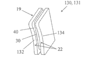
본 발명은 동력 공구를 위한 제어 장치(10) 및 제어 장치를 구비한 동력 공구(12)에 관한 것이다. 제어 장치(10)는 - 수동으로 작동되는 제어기(130)를 구비하는 작동 제어 인터페이스(128), - 임피던스-측정 안전 인터페이스(131)를 포함하고, 여기서 임피던스-측정 인터페이스는 서로 전기적으로 고립된 제1 수동 접촉 전극(132) 및 제2 수동 접촉 전극(134)을 포함하며, 수동 접촉 전극들(132, 134)은 제어기(130) 상에 제공되고 제어기의 수동 베어링 표면에 걸쳐 연장된다. 본 발명은 동력 공구, 특히 전지 가위와 같은 전기 공구를 제어하고 안전한 사용을 보장하는데 적합하다.The present invention relates to a control device (10) for a power tool and a power tool (12) with a control device. The control device 10 comprises an operational control interface 128 having a manually operated controller 130, an impedance-measuring safety interface 131, wherein the impedance-measuring interfaces are electrically isolated from each other. It includes one passive contact electrode 132 and a second passive contact electrode 134, wherein passive contact electrodes 132, 134 are provided on the controller 130 and extend over the passive bearing surface of the controller. The present invention is suitable for controlling power tools, particularly electric tools such as battery shears, and ensuring safe use.
Description
본 발명은 동력 공구의 시작과 정지를 제어하는 장치 및 그러한 제어 장치를 포함하는 안전 공구에 관한 것이다. 제어 장치는 공구를 시동하거나 정지하는 장치이거나 또는 이를 사용하는 동안 공구의 작동을 변경하는 것으로 이해된다. 작동의 변경은 공구가 회전하는 활동 컴포넌트를 나타내는 경우에 회전 속도의 연속적이거나 불연속적인 변경일 수 있다. 또한 활동 컴포넌트 전체 또는 일부의 상대적인 위치의 변경일 수도 있다. 전동 전지 가위의 특수한 경우에 있어서, 이것은 예를 들어, 절단 고리 위에 절단 칼날이 열리고 닫히는 것을 고려한다.The present invention relates to a device for controlling the start and stop of a power tool and a safety tool comprising such a control device. A control device is understood to be a device that starts or stops a tool or alters the operation of a tool while using it. The change in operation can be a continuous or discontinuous change in rotational speed if the tool represents an active component rotating. It may also be a change in the relative position of all or part of the activity component. In the special case of the electric battery scissors, this considers, for example, the cutting blade to open and close over the cutting ring.
작동의 변경은 공구의 작동 모드의 변경도 포함할 수 있다. 예를 들어, 전지 가위에 대해 이것은 칼날이 비례적으로 닫히는 작동 모드에서 양자택일의 임펄스 작동모드로 전환하는 것을 의미할 수 있다. The change in operation may also include a change in the operation mode of the tool. For example, for battery shears, this could mean switching from an operating mode in which the blade is closed proportionally to an alternative impulse operating mode.
공구의 작동의 변경은 또한 도량 또는 작동 범위의 변경일 수도 있다. 계속 전지 가위를 인용하면 이것은 예를 들어, 절단 고리에 상대적인 절단 칼날의 최대 열림 또는 칼날의 최대 행정의 변경의 제어를 고려한다.A change in the operation of the tool may also be a change in weight or range of operation. Continuing to cite shears, this takes into account, for example, control of the maximum opening of the cutting blade relative to the cutting ring or the change of the maximum stroke of the blade.
공구는 공구의 활동 컴포넌트와 작업자의 의도치 않은 접촉의 경우에 작업자가 부상을 입는 것을 방지하거나, 또는 적어도 작업자의 부상이 심각한 정도를 제한할 목적을 위한 자동 비상 정지 장치를 구비하면 안전하다고 여겨진다. A tool is considered safe if it is provided with an automatic emergency stop device for the purpose of preventing the operator from being injured in case of unintended contact of the tool with the active component of the tool, or at least limiting the severity of the operator's injury.
비상 정지 장치는 만일 비상 정지가 작업자의 고의로 개입하지 않고, 다만 부상 위험이 있는 상황의 간단한 감지에 따라 개시될 경우 자동적인 것으로 여겨진다.The emergency stop device is considered to be automatic if the emergency stop is not intentionally intervened by the operator, but is initiated upon simple detection of a situation at risk of injury.
본 발명은 예를 들어, 회전톱, 또는 휴대용 동력 공구 및 특히 이동 칼날 또는 날카롭거나 무딘 활동 컴포넌트를 나타내는 절단 공구를 위한 기계 공구의 응용을 발견한다. 본 발명은 특히, 전단기, 전지 가위, 체인톱, 톱, 그라인더 또는 드릴을 위한 응용을 발견한다.The present invention finds, for example, the application of machine tools for rotary saws, or hand-held power tools and especially for cutting tools exhibiting moving blades or sharp or dull active components. The present invention finds applications in particular for shears, shears, chain saws, saws, grinders or drills.
이 기술분야의 실례들은 다음 문헌들에서 제공된다.Examples in this technical field are provided in the following documents.
FR 2712837FR 2712837
FR 2779669FR 2779669
FR 2831476FR 2831476
FR 2838998FR 2838998
FR 2846729FR 2846729
FR 2963081FR 2963081
FR 3001404FR 3001404
EP 2490865EP 2490865
EP 2825811EP 2825811
US 5025175US 5025175
US 7365955US 7365955
WO2012 / 025456WO2012 / 025456
이들 문헌들은 작업자의 부상을 회피하기 위한 비상 정지 장치를 구비한 전기 제어를 갖는 기계 및 공구를 언급한다.These documents refer to machines and tools with electrical control with emergency stops to avoid operator injury.
이들 문헌들로부터 식물을 다듬는데 한 손을 사용하는 전기 전지 가위와 같은 다양한 공구들이 발견된다. 이 경우에, 작업자는 한 손으로 전기 전지 가위를 쥐고 그의 다른 빈 손을 사용해 이미 잘라낸 또는 자르고자 하는 식물을 다룬다. 부상의 위험은 전지 가위를 쥐고 있지 않은 손이 절단하는 도중에 절단 요소에 바로 근접하거나 또는 접촉할 때 존재한다. 전지 가위 또는 가위의 경우에, 절단 요소는 그 자체가 대부분의 경우에 고정 칼날이나 고리, 및 회전 칼날의 형태로 존재한다. 회전 칼날은 고리에 걸려서 열린 위치 및 닫힌 위치 사이를 회전하여, 회전 칼날과 고리 사이에 전단 효과를 갖는다. 어떤 전단 가위의 절단 요소는 또한 칼날들이 열린 위치에서 닫힌 위치로 지나갈 때 전단 효과를 달성하도록 서로 간에 협동하는 두 개의 움직이는 칼날로 구성될 수 있다.From these documents, a variety of tools are found, such as electric cell scissors that use one hand to trim plants. In this case, the operator holds the electric cell scissors with one hand and uses his other empty hand to handle the plant that has already been cut or cut. The risk of injury exists when a hand that is not holding the battery shears comes in direct contact or contact with the cutting element during cutting. In the case of battery shears or scissors, the cutting elements themselves are in most cases in the form of fixed blades or rings, and rotating blades. The rotating blade is hooked and rotates between an open position and a closed position, and has a shearing effect between the rotating blade and the ring. The cutting element of some shear scissors may also consist of two moving blades that cooperate with each other to achieve a shear effect when the blades pass from an open position to a closed position.
드릴, 그라인더, 회전 또는 체인톱의 경우에, 절단 요소는 축을 중심으로 회전하는 절단 부품들에 존재한다.In the case of a drill, grinder, rotary or chain saw, the cutting element is present in the cutting parts rotating about the axis.
전단기, 분쇄기 또는 회전 톱과 같은 기계 공구의 경우에, 절단 요소들은 그 자체가 축을 중심으로 회전하거나 또는 고정된 프레임에 상대적인 병진 운동을 하는 절단 부품들의 형태로 존재한다.In the case of machine tools such as shears, grinders or rotating saws, the cutting elements themselves are in the form of cutting parts that rotate around an axis or make translational motion relative to a fixed frame.
다양한 수단들이 절단 요소에 손이 바로 근접하거나 또는 접촉하는지를 감지하기 위해 이용된다. 특히 구별되는 것들은 무선-전기 수단, 칼날 상의 전위 감지 수단, 정전 용량 수단 또는 임피던스 측정 수단이다.Various means are used to detect whether the hand is in direct proximity or contact with the cutting element. Particularly distinguished are radio-electric means, potential sensing means on the blade, capacitance means or impedance measurement means.
주지의 안전 장치는 장갑, 신발 또는 통신 링크로 안전 장치와 전기적으로 연결된 비컨을 이용한다. 이 링크는 무선 링크 또는 가능하다면 헤르츠파에 의한 것일 수 있다.Well-known safety devices use gloves, shoes, or beacons that are electrically connected to the safety devices by communication links. This link may be a radio link or, if possible, by Hertz.
장갑을 사용하면, 장갑은 전기 전도체를 갖추고 있고 그 기능은 장갑과 절단 요소 사이의 측정 회로를 형성하는 것이다. 유사하게, 전도성 신발은 접지에 연결되고 작업자의 몸체를 포함한 측정 회로를 형성하는데 사용될 수 있다.When using gloves, the gloves are equipped with electrical conductors and their function is to form a measuring circuit between the gloves and the cutting element. Similarly, conductive shoes can be used to form a measurement circuit that is connected to ground and includes the operator's body.
전자 비컨, 전도성 장갑 및 전도성 신발의 사용 또는 보다 일반화해서 절단 공구와 전기적으로 연결된 전도성 의류품의 사용은 작업자가 절단 요소와 접촉하는 것을 감지하는 역할을 한다. 절단 작동의 비상 정지는, 예를 들어, 전도성 의류품이 절단 요소와 접촉을 감지한 것에 응답하여, 가능한 부상을 회피하거나 심각성을 제한하는 것을 가능케 만든다. The use of electronic beacons, conductive gloves and conductive footwear or, more generally, the use of conductive garments electrically connected to the cutting tool serves to detect the operator's contact with the cutting element. The emergency stop of the cutting operation makes it possible to avoid possible injury or limit the severity, for example, in response to the conductive garment sensing contact with the cutting element.
그러나 주지의 안전 장치들은 작업자에게 수 개의 어려움 또는 단점들을 나타낸다. 이들은 특히 다음을 포함한다:However, well-known safety devices present several difficulties or disadvantages to the operator. These specifically include:
- 전도성 옷과 전지 가위 사이의 유선 연결에 의해 발생하는 불편함,-Discomfort caused by a wired connection between conductive clothes and battery scissors,
- 전도성 옷과 전지 가위 사이의 유선 링크를 자를 위험.-Risk of cutting the wired link between conductive clothing and battery scissors.
[관련 출원][Related applications]
본 발명은 특허 출원 FR 17/71254 및 FR 17/71255가 개시하는 발명의 몇가지 특성들에서 출발하며 이에 대한 원용이 이루어진다. 이는 이들의 개선을 구성한다.The present invention originates and is derived from several characteristics of the inventions disclosed in patent applications FR 17/71254 and FR 17/71255. This constitutes their improvement.
본 발명은 이 기술분야의 장비가 맞닥뜨린 문제들을 극복하는 것을 목표로 한다.The present invention aims to overcome the problems encountered by equipment in this technical field.
또한 기존의 제어 장치를, 예를 들어 활동 컴포넌트 제어 및 안전 기능과 같은, 동시간 작동 기능들을 통합한 개선된 제어 장치로 교체하는 제안을 하는 것을 목표로 한다.It is also aimed at making a proposal to replace the existing control device with an improved control device incorporating simultaneous operation functions, such as, for example, active component control and safety functions.
본 발명의 다른 목표는 제어 장치 및 제어 장치를 통합한 공구로서, 인체공학적이고 믿을 수 있고, 특히 안전 기능까지 고려한 것을 제안하는 것이다.Another object of the present invention is to propose a control device and a tool incorporating the control device, which are ergonomic and reliable, and especially considering safety functions.
이 목표들을 달성하기 위하여, 본 발명은 보다 자세하게는 동력 공구를 위한 제어 장치를 제안하며, 다음을 포함한다:To achieve these goals, the present invention proposes a control device for a power tool in more detail, including:
- 수동 조작되는 제어기를 구비한 작동 제어 인터페이스로서, 제어기를 오프-위치와 적어도 하나의 작동 위치 사이로 이동시키는 수동 베어링 표면을 나타내는, 작동 제어 인터페이스,-An actuation control interface with a manually operated controller, representing an actuating bearing surface that moves the controller between the off-position and at least one actuated position, an actuation control interface,
- 서로 전기적으로 절연된, 제1 수동 접촉 전극 및 제2 수동 접촉 전극을 포함하는 임피던스-측정 안전 인터페이스.-An impedance-measuring safety interface comprising a first passive contact electrode and a second passive contact electrode that are electrically isolated from each other.
수동 접촉 전극들은 제어기 위에 위치하고 제어기의 수동 베어링 표면 위에 연장한다. Passive contact electrodes are located on the controller and extend over the passive bearing surface of the controller.
제어 장치는 동력 공구의 제어 특히 전동 절단 공구의 제어를 하도록 의도될 수 있다.The control device can be intended to control the power tool, in particular the power cutting tool.
제어 장치의 제1 인터페이스는 작동 제어 인터페이스, 즉 공구의 작동을 통제하는 인터페이스이다. 작동 제어 인터페이스는, 전기 신호를 방출하거나, 전기 신호를 변경하거나 또는 제어 회로의 전기 특성, 예를 들어 제어 회로의 저항, 커패시턴스, 인덕턴스 또는 신호의 주파수를 변경한다는 점에서 전기 인터페이스일 수 있다.The first interface of the control device is an operation control interface, that is, an interface that controls the operation of the tool. The operation control interface may be an electrical interface in that it emits an electrical signal, modifies the electrical signal, or changes the electrical characteristics of the control circuit, such as the resistance, capacitance, inductance, or frequency of the signal.
제어기는 작동 제어 인터페이스의 일부이다. 이것은 본질적으로 작업자가 제어기를 누르거나 또는 제어기의 위치를 변경하여 제어를 입력할 수 있게 해준다. 제어기는 예를 들어, 푸시버튼, 레버 트리거 또는 멈춤쇠 형태로 나타날 수 있다.The controller is part of the operation control interface. This essentially allows the operator to enter control by pressing the controller or changing the position of the controller. The controller can appear, for example, in the form of a pushbutton, lever trigger or detent.
작동 제어 인터페이스가 바람직하게는 전기 인터페이스이지만, 이는 예를 들어, 열 구동 엔진의 흡입에 작용하는 기계 인터페이스일 수도 있다.The operation control interface is preferably an electrical interface, but it may also be, for example, a mechanical interface acting on the suction of a heat driven engine.
제어기의 이동은 본질적으로 공구의 정지에 대응하는 오프 위치 및 예를 들어 공구의 작동에 대응하는 적어도 하나의 작동 위치 사이에 있다. 공구의 작동은 본질적으로 공구의 활동 컴포넌트를 운전하는 상태로 설정하는 것으로 이해된다.The movement of the controller is essentially between the off position corresponding to the stop of the tool and at least one operating position corresponding to the operation of the tool, for example. It is understood that the operation of the tool essentially sets the active component of the tool to the driving state.
보다 자세하게는, 제어기는 어떠한 명령도 전송되지 않고 제어 장치를 장착한 공구가 정지 또는 준비 상태에 있는 정지 또는 오프-위치에 있을 수 있다. 제어기는 또한 공구의 하나 또는 여러 작동 상태들 또는 모드들에 대응하는 하나 또는 여러 작동 위치들에 있거나 또는 제어기가 이동하는 크기에 비례하는 명령인 경우에, 공구의 비례하는 작동의 위치에 있을 수도 있다.More specifically, the controller may be in a stopped or off-position where no command is transmitted and the tool equipped with the control device is in a stopped or ready state. The controller may also be in one or several operating positions corresponding to one or several operating states or modes of the tool, or in the case of a command proportional to the size the controller moves, in the position of the tool's proportional operating. .
예를 들면, 비례적인 제어는 드릴 또는 홈 절삭 기계의 경우에 가변하는 회전 속도를 통제할 수 있다. 비례적인 제어는 또한 전지 가위의 고리에 상대적인 전지 가위의 절단 칼날의 상대 위치를 통제할 수 있다.For example, proportional control can control a variable rotational speed in the case of a drill or groove cutting machine. Proportional control can also control the relative position of the cutting blade of the battery shear relative to the ring of the battery shears.
제어기는 한 손으로, 한 손가락으로, 다수의 손가락들로, 또는 어쩌면 손바닥과 같은 손의 다른 부위들에 의해 작동되게 의도된 경우, 수동인 것으로 여겨진다. 손은 맨 손이거나, 특히 제어기와 접촉하는 곳이, 완전히 또는 부분적으로 전기 전도성 장갑으로 덮여 있을 수 있다.A controller is considered manual if it is intended to be operated by one hand, one finger, multiple fingers, or possibly other parts of the hand, such as the palm. The hand may be bare, or in particular where the contact with the controller is completely or partially covered with electrically conductive gloves.
아래의 설명에서 작업자의 손에 대한 언급은 맨 손이나 전도성 장갑으로 덮인 손이라는 사실을 예단하지 않고 손의 부위 또는 제어를 작동하는 손가락을 예단하지 않는다.References to the operator's hand in the description below do not foresee the fact that it is a bare hand or a hand covered with conductive gloves, but do not foresee the fingers acting on the part or control of the hand.
제어기의 수동 베어링 표면은 작업자가 제어기를 작동시킬 때 작업자의 손과 접촉하는 제어기의 부분 또는 부분들을 지정한다. 활성화는 예를 들어 제어기의 베어링 표면 위에 압력을 가함으로써 발생한다.The passive bearing surface of the controller designates a portion or parts of the controller that comes into contact with the operator's hand when the operator operates the controller. Activation occurs, for example, by applying pressure on the bearing surface of the controller.
작동 제어 인터페이스와는 별개의, 제어 장치의 제2 인터페이스는 임피던스-측정 인터페이스이다. 임피던스-측정 인터페이스는 하나 또는 여러 임피던스들, 및 넓게는, 임피던스에 따라 달라지는 하나 또는 여러 전기 특성들을 측정 또는 비교하는 인터페이스를 의미하는 것으로 이해된다. 이것은 예를 들어, 옴 임피던스, 임피던스에 비례해서 변하는 전압 및/또는 전류이다. 특히, 임피던스-측정 인터페이스의 제1 및 제2 전극은 같은 전기 회로의 부분이거나 또는 비교하고자 하는 전기 특성들의 수립을 위한 두 개의 분리된 전기 회로들의 부분일 수 있다. 임피던스-측정 인터페이스의 활용 가능성들의 보다 상세한 설명은 아래에 주어진다.Apart from the operation control interface, the second interface of the control device is an impedance-measuring interface. Impedance-measuring interface is understood to mean an interface that measures or compares one or several impedances, and, broadly, one or several electrical properties that depend on the impedance. This is, for example, ohmic impedance, voltage and/or current varying in proportion to impedance. In particular, the first and second electrodes of the impedance-measurement interface may be part of the same electrical circuit or two separate electrical circuits for establishing electrical characteristics to compare. A more detailed description of the possibilities of using the impedance-measurement interface is given below.
유리하게는, 제어기의 베어링 표면 상에 연장되는 임피던스 측정 인터페이스의 수동 접촉 전극들로 인하여, 작업자가 이 컴포넌트를 눌러서 제어기를 작동시키는 순간에, 임피던스-측정 인터페이스와 동시에 2개의 수동 접촉 전극들과 접촉한 작업자의 손의 존재를 감지하는 것이 가능하다.Advantageously, due to the passive contact electrodes of the impedance measurement interface extending on the bearing surface of the controller, at the moment the operator presses this component to activate the controller, it contacts the two passive contact electrodes simultaneously with the impedance-measurement interface. It is possible to detect the presence of a worker's hand.
추가적으로, 임피던스-측정 인터페이스는 제어 장치의 작업자가 끼고 있는 적어도 하나의 전기적 전도성 장갑을 포함하거나 그와 연관될 수 있다. 전기적 전도성 장갑은 그 전체가 전도성인 장갑이거나 제어기와 접촉하는 곳의 작업자의 손의 부위와 연관된 전기적 전도성 부분을 포함하는 장갑이라고 이해된다. 예를 들어, 손의 어느 한 손가락과 연관된 제어기를 위한 전기 전도성 손가락 골무이다. 장갑의 전도 특성은 임피던스-측정 인터페이스의 수동 접촉 전극들과의 접촉 임피던스를 줄이기 위해 임피던스-측정 인터페이스와 터치할 수도 있는 장갑의 바깥 부분을 일컫는다. 이것은 또한 작업자의 손과 접촉하는 장갑의 안쪽 부분에서부터 적용된다. 이 경우에, 내부 전도성 부분과 외부 전도성 부분은 전기적으로 서로 연결되어 작업자의 손과 수동 접촉 전극들 사이의 접촉을 수립한다. 바람직하게는, 그리고 손과 장갑 사이의 약한 임피던스의 양호한 수준을 수립하기 위하여, 큰 접촉 표면이 주어지는 것이 선호되고 장갑의 내부 부분은 완전히 전도성일 수 있다. 전도성 장갑은 예를 들어, 전도성 금속 섬유(은, 스테인리스 스틸, 니켈, 등) 또는 탄소-기반 섬유를 포함할 수 있다.Additionally, the impedance-measuring interface may include or be associated with at least one electrically conductive glove worn by the operator of the control device. It is understood that the electrically conductive glove is a glove that is entirely conductive or that includes an electrically conductive portion associated with a portion of the operator's hand where it contacts the controller. For example, an electrically conductive finger thimble for a controller associated with one finger of the hand. The conduction characteristic of the glove refers to the outer part of the glove that may touch the impedance-measurement interface to reduce contact impedance with the passive contact electrodes of the impedance-measurement interface. This also applies from the inner part of the glove that comes into contact with the operator's hand. In this case, the inner conductive portion and the outer conductive portion are electrically connected to each other to establish contact between the operator's hand and the passive contact electrodes. Preferably, and to establish a good level of weak impedance between the hand and the glove, it is preferred to be given a large contact surface and the inner part of the glove can be completely conductive. Conductive gloves can include, for example, conductive metal fibers (silver, stainless steel, nickel, etc.) or carbon-based fibers.
제어기로 돌아가서, 그리고 이 컴포넌트의 가능한 유리한 구현에 따르면, 이것은 적어도 하나의 제1 음각 릴리프, 및 흡습성 및 방수성 물질 중에서 선택한 물질을 포함하는 전기 절연 분리기를 나타낼 수 있고, 제1 음각 릴리프, 각각의 분리기는 제1 수동 접촉 전극 및 제2 수동 접촉 전극 사이에, 수동 베어링 표면 위에 연장한다.Returning to the controller, and according to a possible advantageous implementation of this component, it can represent an electrical insulation separator comprising at least one first intaglio relief, and a material selected from hygroscopic and waterproof materials, the first intaglio relief, each separator Between the first passive contact electrode and the second passive contact electrode, extending over the passive bearing surface.
제1 음각 릴리프 또는 분리기의 기능은 제어기에 수분이 쌓여서 임피던스-측정 인터페이스 상에 작업자의 접촉의 감지가 왜곡될 수 있기 때문에 제1 및 제2 전극 사이에 전도성 다리의 형성을 방지하기 위한 것이다. 제어기 상에 쌓일 수 있는 수분은 주변으로부터 또는 작업자의 땀으로부터 동시에 올 수 있다. 예를 들어, 제어 장치가 전기 가위의 부분일 때, 제어기의 수분은, 비가 오는 동안 또는 비가 온 후에 또는 식물이 이슬로 덮여 있는 포도밭 또는 변재를 제거한 과수원에 전지 가위를 사용하는 것으로부터 기인할 수 있다.The function of the first intaglio relief or separator is to prevent the formation of a conductive leg between the first and second electrodes, as moisture builds up in the controller, which may distort the sense of operator's contact on the impedance-measuring interface. The moisture that can build up on the controller can come from the surroundings or from the sweat of the operator at the same time. For example, when the control device is part of the electric shears, the moisture in the controller can result from the use of battery shears in the orchard after rain or after rain or in the orchard where the vegetation or sapwood covered with dew is removed. have.
제어기 상에 얇은 완충 필름이 있는 경우에, 음각 릴리프(들)은 필름 파열에 대비하여 장벽을 형성할 수 있다. 보다 높은 습도의 경우에, 음각 릴리프(들)은 또한 모세관 작용에 의해 수분을 가두거나 또는 수분을 배출하기 위한 채널 또는 배수관을 제공하는데 사용될 수 있다.If there is a thin buffer film on the controller, the negative relief(s) can form a barrier against film rupture. In the case of higher humidity, the intaglio relief(s) can also be used to confine moisture by capillary action or to provide channels or drainage pipes to drain moisture.
제1 음각 릴리프가 제공하는 모든 필름 파열에 대비한 장벽의 추가적인 개선을 위하여, 이것은 각진 테두리들을 갖는 릴리프일 수 있다.For further improvement of the barrier against all film rupture provided by the first intaglio relief, this can be a relief with angled edges.
제어기는 또한 수분을 흡수한 다음 배출할 수 있는, 또는, 반대로, 수분과 반발할 수 있는 분리기를 포함할 수 있다. 이것은 필름에 수분을 방지해서 수동 접촉이 없이 두 개의 수동 접촉 전극들 사이에서 의도치 않은 낮은 임피던스 접촉이 일어나는 것을 방지한다. 분리기는 음각 릴리프 대신에, 또는 음각 릴리프에 더하여 그와 같은 효과를 나타내면서 제공될 수 있다. The controller may also include a separator capable of absorbing and then discharging moisture, or, conversely, repelling moisture. This prevents moisture on the film, thereby preventing unintentional low impedance contact between the two passive contact electrodes without manual contact. The separator can be provided instead of, or in addition to the intaglio relief, exhibiting such an effect.
분리기는 예를 들어, 다공성 세라믹과 같은, 흡습성 재료로 만들어질 수 있다. 분리기는 또한 PVDF (폴리비닐리덴 플루오라이드), PTFE (폴리테트라 플루오로에틸렌), Teflon (폴리테트라 플루오로에틸렌), 또는 방수성 재료로 만들어진 닫힌 기공의 발포제와 같은 방수성 재료로 만들어질 수 있다. 이것은 덩어리일 수 있고 또는 표면 코팅의 형태일 수 있다. 분리기는 수동 접촉 전극들 사이의 스페이서 또는 수동 접촉 전극들의 지지체를 구성하는데 사용될 수 있다.The separator can be made of a hygroscopic material, for example porous ceramics. The separator can also be made of a waterproof material such as PVDF (polyvinylidene fluoride), PTFE (polytetra fluoroethylene), Teflon (polytetra fluoroethylene), or a closed pore blowing agent made of a waterproof material. It can be agglomerated or in the form of a surface coating. The separator can be used to construct a spacer between passive contact electrodes or a support of passive contact electrodes.
제어기가 길쭉한 모양을 나타내는 선호되는 구성에 따르면, 제1 및 제2 수동 접촉 전극 및 상기 제1 음각 릴리프는 제어기 상에 길이방향으로 연장할 수 있다.According to a preferred configuration in which the controller exhibits an elongated shape, the first and second passive contact electrodes and the first intaglio relief can extend longitudinally on the controller.
제어기는 상이한 방식들로 생산될 수 있고; 이는 예를 들어, 레버 트리거 또는 푸시버튼 중 어느 하나를 포함할 수 있다.The controller can be produced in different ways; This can include, for example, either a lever trigger or a pushbutton.
경우에 따라서, 제어기의 작동은 그의 바닥 방향으로 아래로 누르기 위해 또는, 회동하는 레버의 경우 그를 회동시키기 위해 제어기를 누름으로써 이루어질 수 있다.In some cases, the operation of the controller can be achieved by pressing the controller down to push it in the direction of its bottom, or to rotate it in the case of a rotating lever.
제어기가 레버인 제어기의 특수한 가능성 있는 생산에 따르면, 제1 음각 리세스는 수동 베어링 표면을 형성하는 레버의 제1 면 상에 연장할 수 있다. 레버는 레버의 제1 면의 반대편에 레버의 제2 면 상에 연장되는 적어도 하나의 제2 음각 릴리프를 포함할 수 있다.According to the particular possible production of the controller, in which the controller is a lever, the first intaglio recess can extend on the first side of the lever forming the passive bearing surface. The lever can include at least one second intaglio relief extending on the second side of the lever opposite the first side of the lever.
제1 음각 릴리프 및 제2 음각 릴리프는 예를 들어, 단순한, 쪼개진 또는 여러 인접한 릴리프들의 형태일 수 있다.The first intaglio relief and the second intaglio relief can be, for example, in the form of simple, split or several adjacent reliefs.
제어기가 레버인 제어기의 다른 가능한 생산에 따르면, 제1 음각 릴리프는 레버의 제1 면과 레버의 제2 변 사이에 레버를 가로지르는 함몰 공간을 포함할 수 있다. 가로지르는 함몰 공간은 따라서 예를 들어, 전극들을 포함하지 않는 레버의 일 면을 향해 수분이 흐르게 할 수 있다. 함몰 공간은 또한 제2 면의 반대편에 위치한 있을 수 있는 광학 센서의 매개를 통해 제어기에서 작업자의 손의 존재를 감지하는 것을 가능케 한다.According to another possible production of a controller in which the controller is a lever, the first intaglio relief may include a depression space across the lever between the first side of the lever and the second side of the lever. The traversing depression space can thus allow water to flow towards one side of the lever, for example, that does not include electrodes. The recessed space also makes it possible to detect the presence of the operator's hand at the controller through the mediation of an optical sensor that may be located on the opposite side of the second side.
레버의 제1 면 및 레버의 제2 면은, 예를 들어, 레버의 회동 축과 나란하게 마주할 수 있다. 면들 중 하나는 제어기의 베어링 표면을 구성하거나 또는 부분일 수 있고, 따라서 레버를 작동시키는 작업자의 손가락 또는 손을 수용한다.The first surface of the lever and the second surface of the lever, for example, may face the rotation axis of the lever. One of the faces may constitute or be part of the bearing surface of the controller, thus accommodating the operator's finger or hand operating the lever.
푸시버튼이든 레버이든, 제어기는 전기 절연 물질인 중심체 및 중심체의 옆 측면들에 설정된 전기 전도성 물질로 만들어진 부속품들을 포함할 수 있고, 부속품들은 각각 제1 수동 접촉 전극과 제2 수동 접촉 전극 각각을 형성한다.Whether a pushbutton or a lever, the controller can include accessories made of an electrically insulating material, the center body and electrically conductive materials set on the side surfaces of the center body, and the accessories respectively form a first passive contact electrode and a second passive contact electrode, respectively. do.
중심체의 옆 측면들은 오프-위치 및 작동 위치 사이에 제어기의 이동 평면에 평행한 측면들인 것으로 고려된다. 중심체는 금속 부속품들, 서로간에, 전기적으로 절연시키고 결과적으로 수동 접촉 전극들을 전기적으로 절연시키는 역할을 한다. 중심체는 또한 금속 부속품들에 대한 지지체로서의 역할을 할 수 있다.The lateral sides of the center body are considered to be those parallel to the plane of movement of the controller between the off-position and the operating position. The central body serves to electrically insulate the metal accessories, from each other and consequently to the passive contact electrodes. The center body can also serve as a support for metal accessories.
제어기는 작업자가 베어링 표면 상에 가해진 압력을 해제할 때 제어기를 작동 위치에서 정지 위치로 되돌리는 복귀 스프링에 의해 장전될 수 있다.The controller can be loaded by a return spring that returns the controller from the operating position to the stationary position when the operator releases the pressure applied on the bearing surface.
본 발명은 또한 다음을 포함하는 안전 동력 공구에 관한 것이다:The present invention also relates to a safety power tool comprising:
- 전기 전도성의 활동 컴포넌트,-Active component of electrical conductivity,
- 활동 컴포넌트의 전기 절연된 제어 장치,-Electrically insulated control of active components,
- 활동 컴포넌트의 구동 모터-Driving motor of active component
- 활동 컴포넌트와 작업자의 접촉에 반응하는, 전기 특성들의 비교기를 갖는 모니터링 장치,-A monitoring device with a comparator of electrical properties, responsive to the contact between the active component and the operator,
- 모니터링 장치에 의해 서보-구동되는, 활동 컴포넌트를 위한 비상 정지 장치.-Emergency stop device for active components, servo-driven by the monitoring device.
본 발명에 따르면:According to the invention:
- 제어 장치는 앞서 설명한 것과 일치하고,-The control unit is identical to the one described above,
- 활동 컴포넌트의 구동 모터는 제어 장치의 작동 제어 인터페이스의 중계를 통해 제어되고-The drive motor of the active component is controlled through the relay of the operation control interface of the control device
- 모니터링 장치는 제어 장치의 안전 임피던스-측정 인터페이스를 포함한다.-The monitoring device includes the safety impedance-measurement interface of the control device.
공구는 기계 공구 또는 휴대용 공구일 수 있고, 이것은 열기관에 의해 동력을 받는 공구이거나 또는 바람직하게는 전기 동력 공구일 수 있다. 비상 정지 장치는 상이한 컴포넌트들을 포함할 수 있고 그 기능들은 구동 모터로의 동력 공급을 중단하는 것; 구동 모터를 제동하는 것; 활동 컴포넌트를 제동하는 것 및/또는 활동 컴포넌트를 저지하는 것이다. 비상 정지는 또한 활동 컴포넌트의 정상 동작에 반대되는 대항 비상 동작을 개시하고 움직이고 있는 모든 컴포넌트들의 운동 에너지를 상쇄하는 것으로 이루어질 수 있다. 움직이고 있는 컴포넌트들은 활동 컴포넌트, 활동 컴포넌트의 구동 모터 또는 모터를 활동 컴포넌트에 연결시키는 트랜스미션의 것일 수 있다.The tool may be a mechanical tool or a handheld tool, which may be a tool powered by a heat engine or preferably an electric power tool. The emergency stop device may include different components, the functions of which stop the supply of power to the drive motor; Braking a drive motor; Braking an activity component and/or blocking an activity component. The emergency stop may also consist of initiating an emergency action against the normal operation of the active component and canceling the kinetic energy of all components in motion. The moving components may be of an active component, a driving motor of the active component, or a transmission that connects the motor to the active component.
특히, 구동 모터가 전기 모터일 때, 전자 제어 카드는 전기 모터를 사용한 전자기 제동 기능을 제어하기 위하여 제공될 수 있다. 전자기 브레이크는 모터의 플라이휠 상에 작용하거나 또는 심지어 활동 컴포넌트 상에 직접 작용할 수 있다.In particular, when the drive motor is an electric motor, an electronic control card can be provided to control the electromagnetic braking function using the electric motor. The electromagnetic brake can act on the flywheel of the motor or even directly on the active component.
활동 컴포넌트 전부 또는 일부는 전기 전도성 물질로 만들어진다. 그러나, 이것은 그의 표면 상에 가능한 절연 코팅의 유무를 예단하지 않는다. 활동 컴포넌트는, 아래에서 추가적으로 설명된 바와 같이, 활동 컴포넌트와 작업자의 저항식 또는 정전식 접촉을 통하여 공구의 이용의 모니터링에 개입할 수 있다.All or part of the active component is made of an electrically conductive material. However, this does not foresee the presence or absence of a possible insulating coating on its surface. The active component can intervene in monitoring the use of the tool through resistive or capacitive contact of the operator with the active component, as described further below.
활동 컴포넌트는 특히 절단 요소일 수 있다. 이것은 전단기 또는 전지 가위의 절단 칼날을 포함할 수 있다. 활동 컴포넌트는 또한 드릴의 스핀들 또는 만약 가능하다면, 드릴 또는 밀링 커터를 장착한, 홈 절삭 기계를 포함할 수 있다.The activity component can in particular be a cutting element. It may include a shearing blade or a cutting blade of battery shears. The active component may also include a spindle of a drill or, if possible, a groove cutting machine equipped with a drill or milling cutter.
본 발명의 제어 장치는 이중 기능을 갖는다. 제1 기능은 작업자가 공구에 대한 작동 제어들을 입력할 수 있게 해주는 인터페이스 기능이다. 이들은 가령 공구의 활성화, 공구의 특정 작동 모드의 착수 또는 공구의 정지 또는 준비 모드로 복귀와 같은, 양자택일의 제어일 수 있다. 제어는 또한 예를 들어, 구동 모터 및/또는 활동 컴포넌트의 회전 속도를 통제하는 비례적인 제어, 또는 활동 컴포넌트 전체 또는 일부의 비례적인 동작 제어일 수 있다.The control device of the present invention has a dual function. The first function is an interface function that allows the operator to input operation controls for the tool. These can be alternative controls, such as activation of the tool, initiation of a particular mode of operation of the tool, or stop or return to the ready mode of the tool. Control may also be, for example, proportional control that controls the rotational speed of the drive motor and/or active component, or proportional motion control of all or part of the active component.
제어 장치는 또한 제어 장치의 임피던스-측정 인터페이스를 포함하는 공구의 모니터링 장치를 이용한 모니터링 기능을 가질 수 있다.The control device can also have a monitoring function using the tool's monitoring device that includes the control device's impedance-measuring interface.
모니터링 장치의 여러 가능한 구성 및 임피던스-측정 인터페이스의 이용은 아래에 설명된다.The various possible configurations of monitoring devices and the use of impedance-measurement interfaces are described below.
제1 가능성에 따르면, 모니터링 장치는 다음을 포함한다:According to a first possibility, the monitoring device comprises:
- 제1 수동 접촉 전극, 제1 전기 임피던스 및 활동 컴포넌트를 포함하는 제1 전기 회로. 제1 전기 회로는 작업자가 상기 제1 수동 접촉 전극 및 활동 컴포넌트와 동시에 접촉하면 닫힐 수 있다,-A first electrical circuit comprising a first passive contact electrode, a first electrical impedance and an active component. The first electrical circuit can be closed when an operator contacts the first passive contact electrode and active component simultaneously,
- 제1 및 제2 수동 접촉 전극, 제1 전기 임피던스 및 제2 전기 임피던스를 포함하는 제2 전기 회로; 제2 전기 회로는 작업자가 제1 및 제2 수동 접촉 전극과 동시에 접촉하면 닫힐 수 있다,-A second electrical circuit comprising first and second passive contact electrodes, a first electrical impedance and a second electrical impedance; The second electrical circuit can be closed when the operator contacts the first and second passive contact electrodes simultaneously,
- 제1 전기 회로의 임피던스 특성 및 제2 전기 회로의 임피던스 특성에 대한 적어도 하나의 측정 장치,At least one measuring device for the impedance characteristics of the first electrical circuit and the impedance characteristics of the second electrical circuit,
- 제1 전기 회로의 임피던스 특성과 제2 전기 회로의 임피던스 특성에 따라 달라지는 적어도 하나의 임계 특성의 비교기, 비교기는 임계 특성을 교차할 경우에 비상 정지를 야기하는 비상 정지 장치와 연결된다.-A comparator of at least one critical characteristic that depends on the impedance characteristic of the first electrical circuit and the impedance characteristic of the second electrical circuit, the comparator is connected to an emergency stop device that causes an emergency stop when crossing the critical characteristic.
용어 “제1 임피던스” 또는 “제2 임피던스”는 각기 저항성 컴포넌트뿐만 아니라 유도성 및/또는 용량성 컴포넌트도 포함할 수 있는 하나 또는 여러 전기 컴포넌트를 지칭한다. 선호되는 구현에 있어서, 제1 임피던스 및 제2 임피던스는 각각 정해진 값의 전기 저항과 같은 전기 컴포넌트에 의해 형성될 수 있다. 제1 임피던스 및 제2 임피던스는 따라서 고정되고 알고 있는 옴 값들을 나타낸다.The terms “first impedance” or “second impedance” refer to one or several electrical components, each of which may include inductive and/or capacitive components as well as resistive components. In a preferred implementation, the first impedance and the second impedance can each be formed by electrical components, such as electrical resistance of a predetermined value. The first impedance and the second impedance are thus fixed and represent known ohmic values.
더욱이, 제1 및 제2 전기 회로에 관하여, “임피던스 특성”은 전압, 전류의 값, 옴 값, 또는 보다 일반화해서 제1 전기 회로 및 제2 전기 회로의 임피던스 각각에 연결된 전기 특성을 의미한다. 임피던스 특성은 측정 장치에 의해 수립된다. 임계 특성은 또한 제2 전기 회로의 임피던스 트것ㅇ에 따라 달라지는 전압, 전류의 값 또는 옴 값일 수 있다. 이것은 특히 제2 전기 회로의 임피던스 특성에 비례하거나 또는 그 임피던스 특성과 동일할 수 있다.Moreover, with respect to the first and second electrical circuits, “impedance characteristic” means the electrical characteristic connected to each of the impedances of the first electrical circuit and the second electrical circuit by voltage, current value, ohm value, or more generally. Impedance characteristics are established by the measurement device. The threshold characteristic may also be a value of a voltage, a current, or an ohmic value depending on the impedance tung of the second electrical circuit. This may be in particular proportional to or equal to the impedance characteristic of the second electrical circuit.
작업자의 손이 임피던스-측정 인터페이스의 제1 및 제2 수동 접촉 전극과 동시에 접촉하는 것은 작업자의 손의 매개를 통해 특히 각각의 제1 및 제2 수동 접촉 전극들과 손 사이의 접촉 임피던스의 합에 대응하는 임피던스를 가지고서 이들 전극들의 전기적 연결을 가능하게 한다.Simultaneous contact of the operator's hand with the first and second passive contact electrodes of the impedance-measuring interface is through the operator's hand mediation, in particular to the sum of the contact impedances between the respective first and second passive contact electrodes and the hand. It enables electrical connection of these electrodes with corresponding impedances.
양호한 물리적 그리고 전기적 접촉을 보장하기 위하여, 제어 장치를 작동하는데 사용된 작업자의 손은, 적어도 장갑이 수동 베어링 표면과 마주하는 곳이, 전기 전도성인 장갑으로 덮여서 접촉 임피던스들을 낮출 수 있다. 이후의 설명은 전도성 장갑의 사용 유무를 예단하지 아니하며, 앞서 말한 바와 같이, 전극들과 접촉하는 손의 부위를 예단하지 않는다.To ensure good physical and electrical contact, the operator's hand used to operate the control device can lower contact impedances, at least where the glove faces the passive bearing surface, covered with an electrically conductive glove. The following description does not foresee the presence or absence of the use of conductive gloves, and, as previously mentioned, does not foresee the portion of the hand that contacts the electrodes.
작업자의 손은 임피던스-측정 인터페이스의 수동 접촉 전극들 각각과 상이한 부위에서 접촉하고 따라서 각각의 수동 접촉 전극과의 접촉 임피던스는 다를 수 있다. 이들 임피던스들 각각은 또한 작업자의 손의 상태에 따라, 전극들 상의 그의 압력에 따라, 전극들의 표면 상태에 따라, 대기 상태에 따라 그리고 물론 전도성 장갑을 끼고 있는지 여부에 따라 다르다.The operator's hand contacts at different sites with each of the passive contact electrodes of the impedance-measurement interface and thus the contact impedance with each passive contact electrode can be different. Each of these impedances also depends on the condition of the operator's hand, his pressure on the electrodes, the surface condition of the electrodes, the atmospheric condition and of course whether he is wearing conductive gloves.
임피던스-측정 인터페이스의 수동 접촉 전극들의 적절한 임피던스와 모니터링 장치의 배선을 무시했을 때, 수동 접촉 전극들 각각과 손의 접촉 임피던스들은 제2 전기 회로에서 제1 전기 임피던스 및 제2 전기 임피던스와 직렬로 연결된다. 제1 및 제2 전기 임피던스의 값들은 알고 있고 공구를 제조할 때 설정된다. When the proper impedance of the passive contact electrodes of the impedance-measurement interface and the wiring of the monitoring device are neglected, the contact impedances of each of the passive contact electrodes and the hand are connected in series with the first electrical impedance and the second electrical impedance in the second electrical circuit. do. The values of the first and second electrical impedances are known and set when manufacturing the tool.
제2 회로의 임피던스으 특성의 측정 장치는 그들의 값을 제공하고, 이들 임피던스들의 합을 특징으로 한다.The measuring device for the characteristic of the impedance of the second circuit provides their value and is characterized by the sum of these impedances.
제1 수동 접촉 전극, 제1 전기 임피던스 및 전도성 활동 컴포넌트를 포함하는 제1 전기 회로는 작업자가 임피던스-측정 인터페이스를 터치할 때 열린 회로로 유지된다. 이제, 열려 있을 때, 제1 전기 회로의 총 임피던스는 준-무한이고, 그러므로 반드시 제2 전기 회로의 임피던스보다 더 크다.The first electrical circuit comprising the first passive contact electrode, the first electrical impedance and the conductive active component is maintained as an open circuit when the operator touches the impedance-measuring interface. Now, when open, the total impedance of the first electrical circuit is quasi-infinite, and therefore necessarily greater than the impedance of the second electrical circuit.
그러나, 제1 전기 회로는 대신에 작업자가 전기 전도성 활동 컴포넌트 및 제1 수동 접촉 전극을 동시에 터치하면 닫힌다. 이후의 설명에서, 단순화를 위하여, 고려되는 것은 작업자가 임피던스-측정 인터페이스를 터치하지 않은 손의 한 손가락으로 공구의 활동 컴포넌트를 터치한다. 이후의 설명에서 절단 요소를 터치하는 손가락에 대한 모든 언급은, 그러나, 절단 요소와 접촉하게 될 수 있는 신체 부위를 예단하지 않는다. 본 발명의 안전 장치의 작동은, 실제로 그의 얼굴, 팔뚝, 다리 또는 빈손과 같은 작업자의 몸의 모든 다른 부위가 활동 컴포넌트와 접촉했을 때와 동일하다.However, the first electrical circuit instead closes when the operator simultaneously touches the electrically conductive active component and the first passive contact electrode. In the following description, for simplicity, what is considered is that the operator touches the active component of the tool with one finger of the hand without touching the impedance-measuring interface. All references to fingers touching the cutting element in the following description, however, do not foresee body parts that may come into contact with the cutting element. The operation of the safety device of the present invention is actually the same as when all other parts of the operator's body, such as his face, forearms, legs or empty hands, come into contact with the active component.
제1 전기 회로가 활동 컴포넌트와 손가락의 부주의에 의한 접촉에 의해 닫히면, 임피던스-측정 인터페이스의 제1 수동 접촉 전극과 손의 접촉과 연관해서, 제1 수동 접촉 전극과 손의 접촉 임피던스, 제1 수동 접촉 전극과 접촉한 그의 손과 활동 컴포넌트를 터치하는 손가락 사이의 작업자의 몸의 임피던스, 활동 컴포넌트와 손가락의 접촉 임피던스, 및 활동 컴포넌트는 그들이 제1 전기 회로에서 직렬로 연결되는 것을 알 수 있다.When the first electrical circuit is closed by inadvertent contact with the active component and the finger, in association with the hand contact with the first passive contact electrode of the impedance-measuring interface, the first passive contact electrode and the hand contact impedance, the first passive The impedance of the operator's body between his hand in contact with the contact electrode and the finger touching the active component, the contact impedance of the active component and the finger, and the active component can be seen that they are connected in series in the first electrical circuit.
따라서, 제1 전기 회로의 임피던스 특성의 측정 장치는 이들 임피던스들의 합의 값을 제공한다.Therefore, the apparatus for measuring the impedance characteristics of the first electrical circuit provides the sum of these impedances.
전극들, 배선 및 활동 컴포넌트의 임피던스는 무시될 수 있는 것으로 추정된다. 임피던스-측정 인터페이스를 터치하는 그의 제1 손과 활동 컴포넌트를 터치하는 다른 손 사이의 작업자의 몸의 임피던스의 자릿수는 부수적으로 알려져 있다. 이것은 실제 신체의 전도성과 연결되고 1만 옴 보다 작은 값을 나타낸다. 반면에, 제1 및 제2 전기 회로에 수동 접촉 전극들과 손의 접촉 임피던스뿐만 아니라 손가락과 활동 컴포넌트 사이의 접촉 임피던스 값도 큰 변동성을 나타낼 수 있고 대부분은 작업자의 몸의 임피던스 값보다, 특히 약한 접촉 압력과 약한 전도성을 갖는 손의 피부일 경우에, 훨씬 상회한다. 이제, 활동 컴포넌트와 손가락의 접촉이 부상의 위험에 가까워지면, 활동 컴포넌트와 손가락의 접촉의 임피던스 값은 작업자의 몸의 임피던스 값과 같은 자릿수가 되거나 심지어 더 작아지게 된다.It is assumed that the impedances of the electrodes, wiring and active components are negligible. The number of digits of the operator's body impedance between his first hand touching the impedance-measurement interface and the other hand touching the active component is incidentally known. It is connected to the actual body conductivity and represents a value less than 10,000 ohms. On the other hand, in the first and second electrical circuits, not only the contact impedance of the passive contact electrodes and the hand, but also the contact impedance value between the finger and the active component can exhibit great variability, and most of them are particularly weaker than the operator's body impedance value. In the case of the skin of the hand with contact pressure and weak conductivity, it is much more. Now, when the contact between the active component and the finger approaches the risk of injury, the impedance value of the contact between the active component and the finger becomes the same number of digits as the impedance value of the operator's body, or even smaller.
활동 컴포넌트가 절단 칼날인 특수한 경우에 있어서, 손가락은 칼날이 그와 접촉할 때 상당한 탄력을 나타내고 칼날이 처음 손가락의 표피를 자를 수 있어서 절단을 계속해 나아감에 따라 심각한 부상이 되기 전에 경미한 부상을 일으킬 때에만 상당한 압력을 갖는다. 표피의 찰과상과 같은, 작은 상처를 입는 후자의 경우에, 활동 컴포넌트, 이 경우엔 절단 칼날과 몸의 피하 부위 사이의 접촉 임피던스의 값은 신체의 임피던스의 값보다 상당히 낮다.In the special case where the active component is a cutting blade, the finger exhibits significant elasticity when the blade comes into contact with it, and when the blade can cut the epidermis of the first finger, causing minor injuries before serious injury as the blade continues to cut. Only has significant pressure. In the latter case, such as the cutaneous abrasion, the value of the contact impedance between the active component, in this case the cutting blade and the subcutaneous part of the body, is significantly lower than that of the body.
그러므로, 이것으로부터 추론할 수 있는 것은 심각한 접촉의 경우에 활동 컴포넌트에 접촉 임피던스의 값은 신체의 임피던스 값보다 낮다는 것이다. 이 자릿수의 임피던스의 감지는 활동 컴포넌트와 작업자의 갑작스런 그리고 의도치 않은 접촉의 존재의 매우 높은 가능성을 식별할 수 있게 해준다.Therefore, it can be deduced from this that in the case of severe contact, the value of the contact impedance on the active component is lower than the body impedance value. The detection of this digit's impedance makes it possible to identify the very high probability of the presence of sudden and unintentional contact between the active component and the operator.
임피던스-측정 인터페이스를 터치하는 작업자의 손의 접촉 임피던스의 경우엔 그와 같지 않다. 이 접촉 임피던스는 더 상당한 비율로 변할 수 있다. 실제로, 제1 회로의 임피던스의 단순한 측정 하나만으로는 작업자와 활동 컴포넌트 사이의 접촉의 존재를 식별하는 것이 가능하지 않다.This is not the case with the contact impedance of the operator's hand touching the impedance-measurement interface. This contact impedance can change at a more significant rate. Indeed, it is not possible to discern the presence of contact between the operator and the active component with only a simple measurement of the impedance of the first circuit.
활동 컴포넌트 상에 작은 부상이 있자마자, 접촉 임피던스는 매우 빠르게 신체 임피던스 보다 낮은 값으로 떨어지고 절단 또는 깊은 부상이 있을 때 수 백 옴의 매우 낮은 값에 이르기까지 더 떨어진다. 이러한 접촉의 임계 임피던스 특성은, 그의 전반적으로 낮은 값과 신체의 임피던스보다 낮은 자릿수에 있는 것으로 추정되는 모든 경우를 고려하였을 때, 작업자의 손과 임피던스-측정 인터페이스의 제1 수동 접촉 전극 사이의 접촉 임피던스의 가능한 변동에 의해 크게 가려진다. 그러므로, 제1 회로의 임피던스 특성의 단순 측정에 의해서 활동 컴포넌트에 접촉 위험의 존재를 충분히 신뢰할 수 있는 방식으로 특징짓는 것은 가능하지 않다.As soon as there is a small injury on the active component, the contact impedance drops very quickly to a value lower than the body impedance and falls further down to a very low value of hundreds of ohms when cutting or deep injury. The critical impedance characteristic of this contact is the contact impedance between the operator's hand and the first passive contact electrode of the impedance-measurement interface, taking into account all cases presumed to be at their overall lower values and digits lower than the body's impedance. Is largely obscured by possible variations of Therefore, it is not possible to characterize the presence of the danger of contact to the active component in a sufficiently reliable manner by a simple measurement of the impedance characteristic of the first circuit.
그러므로 작업자의 손가락과 활동 컴포넌트 사이의 접촉의 확실성을 수립할 수 있게 해주는 임계 값을 설정하는 것; 및 작업자의 손과 임피던스-측정 인터페이스 사이의 접촉 특성의 변동을 없애는 것은 중요하다.Therefore, setting a threshold value that allows establishing the certainty of the contact between the operator's finger and the activity component; And it is important to eliminate variations in the contact characteristics between the operator's hand and the impedance-measurement interface.
이것은, 본 발명에 따르면, 제2 회로의 임피던스 특성으로부터 임계 특성을 설정함으로써 일어난다. 그래서 제1 전기 회로의 임피던스를 제2 임피던스의 것과 비교하여, 수동 접촉 전극들과 손의 접촉 임피던스 특히 임피던스-측정 인터페이스의 제1 수동 접촉 전극과 손의 접촉 임피던스 그리고 특별히 손과 제1 수동 접촉 전극의 접촉 임피던스의 영향을 자체적으로 없앰으로써 가능해진다. This occurs according to the present invention, by setting the critical characteristic from the impedance characteristic of the second circuit. So by comparing the impedance of the first electrical circuit with that of the second impedance, the contact impedance of the passive contact electrodes and the hand, in particular the contact impedance of the first passive contact electrode and the hand of the impedance-measuring interface and in particular the hand and first passive contact electrode It becomes possible by eliminating the influence of the contact impedance of itself.
제1 전기 회로의 높은 임피던스 값이 제2 전기 회로 상에서 수행된 측정으로부터 결정된 임계치보다 낮은 값을 향해서 지나갈 경우에, 그러면 작업자와 활동 컴포넌트 사이의 접촉의 매우 높은 위험이 있다고 결정한다. 그리고 비상 정지 장치는 작동된다.If the high impedance value of the first electrical circuit passes towards a value lower than the threshold determined from measurements performed on the second electrical circuit, then it is determined that there is a very high risk of contact between the operator and the active component. And the emergency stop device is activated.
따라서, 앞서 언급한 바와 같이, 임계 특성은 기준 회로로서 역할을 하는 제2 전기 회로의 임피던스 특성에 따라서 설정된다.Therefore, as mentioned above, the threshold characteristic is set according to the impedance characteristic of the second electrical circuit serving as a reference circuit.
제2 전기 회로의 임피던스는 제1 임피던스, 제2 임피던스 및 수동 접촉 전극들의 손의 접촉 임피던스들의 합과 같다. 제1 임피던스 및 제2 임피던스의 합은 바람직하게는 작업자의 몸의 추정 임피던스와 심각한 부상 없이 활동 컴포넌트 상에 손가락의 추정된 접촉 임피던스의 합을 능가하는 값으로 설정된다. 예를 들어, 임피던스들과 임피던스 특성들을 옴으로 표현하였을 때, 제1 및 제2 임피던스의 누적 값은 20㏀보다 크게, 바람직하게는 100㏀보다 크게 선택될 수 있다. 몸의 임피던스 및 손가락의 접촉 임피던스는 각각 10㏀보다 작게 추정된다. 후자는 임피던스-측정 인터페이스를 터치하는 작업자의 손이 전도성 장갑으로 덮여 있어서 더욱더 약하다. 그러한 경우에 그리고 손가락이 활동 컴포넌트와 접촉이 없는 경우에, 제1 회로의 임피던스는 준-무한이고 명백히 20㏀ 또는 100㏀보다 크다. 부상으로부터 발생하는 것보다 큰 임피던스 값을 선택하는 것은 장치를 보다 안전하게 만들고, 경미한 부상을 포함한, 부상을 회피할 수 있게 해준다.The impedance of the second electrical circuit is equal to the sum of the first impedance, the second impedance and the contact impedances of the hands of the passive contact electrodes. The sum of the first impedance and the second impedance is preferably set to a value that exceeds the sum of the estimated impedance of the operator's body and the estimated contact impedance of the finger on the active component without serious injury. For example, when the impedances and impedance characteristics are expressed in ohms, the cumulative values of the first and second impedances may be selected to be greater than 20 kHz, preferably greater than 100 kHz. The impedance of the body and the contact impedance of the fingers are estimated to be less than 10 dB each. The latter is even weaker as the hands of the operator touching the impedance-measurement interface are covered with conductive gloves. In such a case and when the finger has no contact with the active component, the impedance of the first circuit is quasi-infinite and is clearly greater than 20 dB or 100 dB. Choosing an impedance value greater than that resulting from the injury makes the device safer and avoids injury, including minor injuries.
손가락이 활동 컴포넌트와 접촉할 때, 작업자의 몸과 활동 컴포넌트 상의 그의 손가락의 접촉의 임피던스는, 제1 전기 회로에서 제2 전기 회로의 제1 및 제2 전기 임피던스의 합의 임피던스 값보다 떨어지게 된다. 그래서, 제1 전기 회로의 측정된 임피던스의 특성은 임계 임피던스 특성보다 작아지는, 즉 최소한 임계 특성을 교차한다. 상기해야 할 것은 측정 임피던스 특성은 전압, 전류 또는 옴 값의 형태로 표현될 수 있다. 경우에 따라서, 제1 회로의 임피던스 특성이 임계 특성보다 높은 값에서 임계 특성보다 낮은 값으로 이행(전압 또는 임피던스의 경우)하거나 또는 임계 특성보다 낮은 값에서 임계 특성보다 높은 값으로 이행(전류의 경우)할 때 임계 값을 넘어간다.When a finger contacts the active component, the impedance of the operator's body and his finger's contact on the active component is less than the impedance value of the sum of the first and second electrical impedances of the second electrical circuit in the first electrical circuit. Thus, the characteristic of the measured impedance of the first electrical circuit becomes smaller than the critical impedance characteristic, that is, at least crosses the critical characteristic. It should be noted that the measurement impedance characteristic can be expressed in the form of voltage, current or ohmic values. In some cases, the impedance characteristic of the first circuit shifts from a value higher than the threshold characteristic to a value lower than the threshold characteristic (for voltage or impedance), or from a value lower than the threshold characteristic to a value higher than the threshold characteristic (for current) ) Exceeds the threshold.
주목해야 할 것은 제1 임피던스 및 제2 전기 임피던스의 값들은 작업자의 몸의 임피던스와 손가락의 접촉 임피던스의 합의 추정된 값보다 반드시 높아야 하는 것은 아니다. 사실은, 제2 회로의 임피던스 특성에 따라 달라지게, 특히 이 임피던스 특성에 비례하여 달라지도록 임계 특성을 선택함으로써, 공구의 안전성을 최적화하기 위한 비례 계수로 임계 특성을 조절하는 것이 가능하다.It should be noted that the values of the first impedance and the second electrical impedance are not necessarily higher than the estimated values of the sum of the operator's body impedance and the finger's contact impedance. In fact, it is possible to adjust the critical characteristic with a proportionality coefficient for optimizing the safety of the tool, by selecting the critical characteristic so that it depends on the impedance characteristic of the second circuit, in particular, proportional to this impedance characteristic.
바람직한 실시 형태에 따르면, 다음의 특성들 중 하나 또는 여럿은 보유될 수도 있다.According to a preferred embodiment, one or several of the following properties may be retained.
- 제2 전기 임피던스는 20㏀ 보다 큰 바람직하게는 100㏀ 보다 큰 옴 값을 나타낸다.-The second electrical impedance exhibits an ohm value greater than 20 kPa, preferably greater than 100 kPa.
- 제1 전기 임피던스는 제2 전기 임피던스와 같은 옴 값을 나타낸다.-The first electrical impedance represents the same ohmic value as the second electrical impedance.
- 제1 전기 임피던스 및 제2 전기 임피던스는 순수히 저항성이다.-The first electrical impedance and the second electrical impedance are purely resistive.
특히, 제1 전기 임피던스는 제2 전기 임피던스와 같고 20㏀보다 큰 옴 값을 나타내고, 제1 임계 특성은 제2 회로의 임피던스 특성과 같도록 선택될 수 있다.In particular, the first electrical impedance is equal to the second electrical impedance and exhibits an ohm value greater than 20 μs, and the first critical characteristic can be selected to be the same as the impedance characteristic of the second circuit.
제1 전기 회로의 임피던스 특성의 측정 및 제2 전기 회로의 임피던스 특성의 측정은 반드시 동시에 일어날 필요는 없지만 활동 컴포넌트의 활성화에 따라서, 특히 전지 가위의 절단 활성화에 따라서 교대로 될 순 있다. 교대로 측정하는 것은 실제로는 두 개의 회로의 임피던스 특성들을 측정하기 위하여 하나의 고유의 측정 장치를 사용하는 것을 가능케 한다.The measurement of the impedance characteristic of the first electrical circuit and the measurement of the impedance characteristic of the second electrical circuit do not necessarily occur at the same time, but may be alternating depending on the activation of the active component, particularly depending on the activation of the cutting of the battery scissors. Alternate measurements make it possible to actually use one unique measuring device to measure the impedance characteristics of two circuits.
이 경우에, 제2 전기 회로는 스위치를 포함할 수 있고; 스위치는 작동 개시할 때 제2 회로를 열고, 작동 개시가 없을 시에는 제2 회로를 닫는 작동 제어 인터페이스에 의해 서보-구동되고; 측정 장치는 제2 회로가 열렸을 때 제1 전기 회로의 임피던스 특성을 측정하고 제2 회로가 닫혔을 때 제2 전기 회로의 임피던스 특성을 측정하도록 구성된다.In this case, the second electrical circuit can include a switch; The switch is servo-driven by an operation control interface that opens the second circuit when it starts to operate, and closes the second circuit when there is no start of operation; The measuring device is configured to measure the impedance characteristic of the first electrical circuit when the second circuit is opened and the impedance characteristic of the second electrical circuit when the second circuit is closed.
용어 “스위치”는 여기서 기능적인 방식으로서 이해된다. 이것은 전기기계적 스위치 또는 전도 상태에서 차단 상태로 그리고 그 반대로 되는 트랜지스터 스위치일 수 있다.The term “switch” is understood here as a functional way. This can be an electromechanical switch or a transistor switch that goes from a conducting state to a blocking state and vice versa.
스위치는 그 열림이 제어기의 작동에 의해 기계적 또는 전기적으로 서보-구동되면 작동 제어 인터페이스에 의해 서보-구동되는 것으로 고려된다.A switch is considered to be servo-driven by an operation control interface if its opening is servo-driven mechanically or electrically by operation of the controller.
여기서 문제가 되는 작동 요청은 특히 활동 컴포넌트가 활동 절단 요소일 때 절단 제어일 수 있다.The operational request in question here may be the cutting control, especially when the active component is an active cutting element.
제1 전기 회로의 임피던스 특성과 제2 전기 회로의 임피던스 특성의 택일적 측정의 경우에, 제2 전기 회로의 임피던스 특성에 따라 결정되는 임계 값은 정기적인 시간 간격으로 및/또는 그 임피던스 특성을 새로이 측정할 때마다 수정 및 갱신될 수 있다.In the case of the alternative measurement of the impedance characteristic of the first electrical circuit and the impedance characteristic of the second electrical circuit, the threshold value determined according to the impedance characteristic of the second electrical circuit is periodically and/or refreshed. It can be revised and updated with every measurement.
또한, 공구는 임계 특성의 저장 메모리를 포함할 수 있다. 메모리는 새로운 측정 때마다 리프레시될 수 있고, 저장된 값은 비교기에 제공된다.In addition, the tool may include storage memory of critical characteristics. The memory can be refreshed with every new measurement, and the stored values are provided to the comparator.
이전에 언급한 바와 같이, 측정 장치는 제1 및 제2 회로의 임피던스를 측정할 필요는 없지만, 적어도 임피던스 특성, 즉 임피던스와 연관된 특성은 측정해야 한다. 특히, 측정 장치는 제1 및 제2 전기 회로와 직렬로 연결된 전류원 및:As mentioned previously, the measuring device need not measure the impedance of the first and second circuits, but at least the impedance characteristic, i.e. the characteristic associated with the impedance, must be measured. In particular, the measuring device comprises a current source connected in series with the first and second electrical circuits and:
- 제1 임피던스의 단자들과 병렬로 연결된 전압계,-A voltmeter connected in parallel with the terminals of the first impedance,
- 제1 임피던스와 직렬로 연결된, 전류계, 또는 저항계-An ammeter, or ohmmeter, connected in series with the first impedance
중 적어도 하나를 포함할 수 있다.It may include at least one of.
이 경우에, 전압계로 기록된 전압, 전류계로 기록된 전류 또는 저항계로 기록된 임피던스는 임피던스 특성으로서 사용가능하다.In this case, the voltage recorded by the voltmeter, the current recorded by the ammeter or the impedance recorded by the ohmmeter can be used as the impedance characteristic.
임계 특성은 전압, 임피던스 또는 임계 전류로서 비교할 수 있는 방식으로 설정될 수 있다.The threshold characteristic can be set in a way that can be compared as a voltage, impedance or threshold current.
손가락이 활동 컴포넌트에 접촉으로 인한 제1 전기 회로의 닫힘은, 필요하다면 제1 회로를 관통하는 전류의 증가, 제1 임피던스의 단자들에서의 전압의 감소 또는 임피던스 특성의 감소, 그에 따른 임계 특성의 교차를 촉발시킨다.Closing of the first electrical circuit due to the contact of the finger with the active component, if necessary, increases the current through the first circuit, decreases the voltage at the terminals of the first impedance or decreases the impedance characteristic, and thus the threshold characteristic. Trigger the crossover
개선된 실시 형태에 따르면, 측정 장치를 위한 전력원은 교류전원일 수 있다. 예를 들어, 이것은 10 ㎑의 교류주파수를 갖는 전원이다. 교류 전원을 사용함으로써, 공구의 전도성의 활동 컴포넌트가 특히 그의 부식을 방지하기 위해 절연 코팅으로 코팅되어 있는 공구로 본 발명을 실시하는 것을 고려할 수 있다. 이것은 예를 들어, 절단 동안 카운터-칼날 위를 미끄러지는 것을 용이하게 하기 위하여 전지 가위의 칼날이 얇은 PTFE 코팅으로 덮여 있는 경우라 할 수 있다. 활동 컴포넌트와 손가락의 접촉은 이 경우에 주로 정전 용량성 접촉이 된다. According to an improved embodiment, the power source for the measuring device may be an AC power source. For example, it is a power source with an alternating frequency of 10 kHz. By using an alternating current source, it is conceivable to practice the invention with a tool in which the conductive active component of the tool is coated with an insulating coating, in particular to prevent its corrosion. This can be the case, for example, when the blade of the battery shear is covered with a thin PTFE coating to facilitate sliding over the counter-blade during cutting. The contact of the active component with the finger is primarily a capacitive contact in this case.
이후의 설명은 모니터링 장치의 구성과 임피던스-측정 인터페이스의 이용의 다른 가능성에 관한 것이다. 이 다른 가능한 구성에 따르면, 모니터링 장치는 다음을 포함할 수 있다:The following description relates to the configuration of the monitoring device and other possibilities of using the impedance-measurement interface. According to this other possible configuration, the monitoring device may include:
- 임피던스-측정 인터페이스의 제1 수동 접촉 전극 및 활동 컴포넌트를 포함하는 전기 모니터링 회로, 전기 모니터링은 작업자가 상기 제1 수동 접촉 전극 및 활동 컴포넌트를 동시에 접촉하면 닫을 수 있다.An electrical monitoring circuit comprising a first passive contact electrode and an active component of the impedance-measurement interface, the electrical monitoring can be closed when an operator contacts the first passive contact electrode and the active component simultaneously.
- 제1 전기 회로에 모니터링 전류의 발전기,-Generator of monitoring current in the first electrical circuit,
- 활동 컴포넌트와 제2 수동 접촉 전극 사이의 모니터링 전압의 측정 장치,-A device for measuring the monitoring voltage between the active component and the second passive contact electrode,
모니터링 전압에 따라 달라지는 적어도 하나의 모니터링 전기 특성과 신체 전도 임피던스 값을 증가시킨 임피던스 값에 따라 달라지는 전기 임계 특성의 비교기; 비교기는 비상 정지 장치와 연결되어서 전기 모니터링 특성이 임계 전기 특성을 교차하면 비상 정지를 일으킨다.A comparator of at least one monitoring electrical characteristic that is dependent on the monitoring voltage and an electrical threshold characteristic that is dependent on the impedance value which has increased the body conduction impedance value; The comparator is connected to the emergency stop device to cause an emergency stop when the electrical monitoring characteristic crosses the critical electrical characteristic.
활동 컴포넌트와 임피던스-측정 인터페이스의 제2 수동 접촉 전극 사이의 모니터링 전압의 측정 장치는 바람직하게는 전압계와 같은 고 임피던스 측정 장치일 수 있다. 그의 내부 임피던스는 전기 모니터링 회로에 수반된 임피던스들보다 수 자릿수 더 커서, 전기 모니터링 회로에 흐르는 전류를 방해하지 않는다. 이것은 예를 들어, 10㏁보다 크다. 모니터링 전압은 활동 컴포넌트의 전위에 상대적으로 측정되고, 그 전위는 바람직하게는 공구의 접지에 대응한다. 이것은 또한 정전위에 상대적으로, 접지에 상대적으로 또는 활동 컴포넌트에 상대적으로, 측정되거나 결정될 수 있다.The measuring device of the monitoring voltage between the active component and the second passive contact electrode of the impedance-measuring interface may preferably be a high impedance measuring device such as a voltmeter. Its internal impedance is several orders of magnitude larger than the impedances involved in the electrical monitoring circuit, so it does not interfere with the current flowing through the electrical monitoring circuit. This is, for example, greater than 10 kPa. The monitoring voltage is measured relative to the potential of the active component, which potential preferably corresponds to the ground of the tool. It can also be measured or determined relative to an electrostatic potential, relative to ground or relative to an active component.
모니터링 전기 특성은 전압, 전류, 임피던스 값 또는 심지어 컨덕턴스 값의 형태로 표현될 수 있는 특성일 수 있다. 이것은 옴의 법칙에 따라 모니터링 전압에 기초한다.Monitoring electrical properties can be properties that can be expressed in the form of voltage, current, impedance values or even conductance values. It is based on the monitoring voltage according to Ohm's law.
신체 전도 임피던스 및 특히 신체 임피던스 값을 증가시킨 값에 기초하는 임계 특성에 대해서도 똑같이 해당된다. 이것은 또한 옴의 법칙과 전기 회로의 임피던스 값을 적용하여 전압, 전류, 임피던스 값 또는 컨덕턴스 값의 형태로 수립될 수 있다.The same holds true for the body conduction impedance and, in particular, the critical characteristic based on the value of increasing the body impedance value. It can also be established in the form of a voltage, current, impedance value or conductance value by applying Ohm's law and the impedance value of the electrical circuit.
모니터링 전기 특성 및 임계 전기 특성의 표현의 다른 형태들은 아래 기재에서 설명된다.Other forms of representation of monitoring electrical properties and critical electrical properties are described below.
전기 모니터링 회로는, 앞서 언급한 바와 같이, 제1 수동 접촉 전극, 및 전기 전도성 활동 컴포넌트를 포함한다. 이것은 작업자가 공구의 임피던스-측정 인터페이스의 제1 수동 접촉 전극과 활동 컴포넌트를 동시에 터치하면 닫힌다.The electrical monitoring circuit, as mentioned above, includes a first passive contact electrode, and an electrically conductive active component. It closes when the operator touches the first passive contact electrode and the active component of the tool's impedance-measuring interface simultaneously.
단순화를 위하여, 언제나 작업자가 그의 한 손으로 임피던스-측정 인터페이스의 제1 수동 접촉 전극을 터치하고, 그가 그의 다른 손의 손가락으로 활동 컴포넌트를 터치하여 부상을 입을 위험이 있는 것으로 고려한다. 이 선택은 그러나 활동 컴포넌트를 터치한 신체의 부위에 관한 어떠한 제한도 암시하지 않는다.For simplicity, it is always considered that the operator is in danger of injury by touching the first passive contact electrode of the impedance-measurement interface with one hand and he touching the active component with the finger of his other hand. This choice, however, does not imply any limitations on the parts of the body that have touched the active component.
따라서, 작업자가 임피던스-측정 인터페이스의 제1 수동 접촉 전극과 활동 컴포넌트를 동시에 터치할 때, 수 개의 임피던스들은 제1 수동 접촉 전극과 활동 컴포넌트 사이의 측정 회로에 직렬로 연결되어 있는 것이 발견된다. 이들은:Thus, it is found that when an operator simultaneously touches the first passive contact electrode and the active component of the impedance-measuring interface, several impedances are connected in series to the measuring circuit between the first passive contact electrode and the active component. These are:
- ZM1으로 표시되는, 손과 제1 수동 접촉 전극 사이의 접촉 임피던스,The contact impedance between the hand and the first passive contact electrode, denoted by Z M1 ,
- ZC로 표시되는, 제1 수동 접촉 전극을 터치한 손과 다른 손의 손가락 사이의, 작업자의 몸의 임피던스, 그리고-The impedance of the operator's body, between the hand touching the first passive contact electrode and the finger of the other hand, denoted by Z C , and
- ZD로 표시되는, 손가락과 활동 컴포넌트 사이의 접촉 임피던스이다.-The contact impedance between the finger and the active component, denoted by Z D.
더욱이, 공구가 전지 가위인 특수한 경우에, ZV로 언급하는 것은, 식물, 예를 들어 포도나무 덩굴의 임피던스, 및 작업자가 빈 손으로 붙잡거나 또는 활동 컴포넌트로 자르는 식물 또는 물체 상에 손가락 또는 보다 일반적으로 손의 접촉 임피던스의 합이다. 만약 가능하다면, 붙잡은 물체는 격자 울타리 와이어일 수 있다. 다른 공구들에 대해선 값 ZV는, 그 재료가 작업자가 빈 손으로 터치한다는 가정 하에, 손가락이 접촉하는 그 재료와 관련된 절단하거나 또는 기계 가공하는 재료를 특징짓는다. Moreover, in the special case where the tool is a battery shear, Z V refers to the impedance of a plant, such as a vine, and a finger or more on a plant or object that the worker holds with an empty hand or cuts into an active component. It is usually the sum of the contact impedance of the hand. If possible, the captured object may be a grid fence wire. For other tools, the value Z V characterizes the cutting or machining material associated with the material to which the finger touches, assuming the material is touched by the operator with an empty hand.
제1 수동 접촉 전극과 활동 컴포넌트의 적절한 임피던스 값들을 무시함으로써, ZT로 표시되는 전기 모니터링 회로의 총 임피던스는 세 가지 값들을 취할 수 있다:By ignoring the appropriate impedance values of the first passive contact electrode and active component, the total impedance of the electrical monitoring circuit denoted Z T can take three values:
무한 값 ZT = ∞ , 활동 컴포넌트가 터치되지 않을 때,Infinite value Z T = ∞, when the active component is not touched,
값 ZT = ZM1 + ZC + ZD 손가락이 활동 컴포넌트를 터치할 때,Value Z T = Z M1 + Z C + Z D When a finger touches the active component,
값 ZT = ZM1 + ZC + ZV 빈 손으로 잡은 재료가 활동 컴포넌트를 터치할 때.Value Z T = Z M1 + Z C + Z V When an empty handed material touches the active component.
임피던스-측정 인터페이스를 터치한 그의 제1 손과 활동 컴포넌트를 터치할 수 있는 그의 다른 손의 손가락 사이의, 작업자의 몸의 임피던스 값 ZC의 자릿수는 쉽게 평가될 수 있다. 이는 그자의 임피던스가 1만 옴 보다 작은 값을 갖는 신체의 전도도이다. 손과 제1 수동 접촉 전극의 접촉 임피던스 ZM1의 값뿐만 아니라 손가락과 활동 컴포넌트 사이의 접촉 임피던스 ZD의 값, 또는 활동 컴포넌트와 접촉하는 재료의 중간 임피던스를 포함하는 임피던스 ZV는 큰 가변성을 나타낼 수 있고 대부분 특히 약한 전도성을 갖는 손의 피부의 부위로 약한 접촉 압력이 있는 경우 작업자의 몸의 임피던스의 값보다 훨씬 더 크다Between the first hand touching the impedance-measurement interface and the fingers of his other hand capable of touching the activity component, the number of digits of the operator's body impedance value Z C can be easily evaluated. This is the conductivity of the body whose impedance is less than 10,000 ohms. Hand and the impedance as well as the value of the first passive contact the electrode contact impedance Z M1 of an intermediate impedance of the material in contact with the finger and the activity value of the contact impedance Z D between components, or active components Z V will represent a large variability It is much larger than the value of the impedance of the operator's body, especially if there is a weak contact pressure to the part of the skin of the hand that is particularly weakly conductive.
이후의 설명에서, 손가락이 활동 컴포넌트에 직접 접촉이 이루어지는 것만 언급한다. 실제로, 손가락이 중간 재료와 접촉하는 상황은 작업자에게 위험을 주지 않는다. 임피던스 값 ZV이 ZD에 근접한, 즉 중간 재료가 좋은 전기 전도체인 경우 비상 정지 장치가 트리거될 수도 잇다.In the following description, only the finger is making direct contact with the active component. Indeed, the situation where the fingers come in contact with the intermediate material poses no danger to the operator. If the impedance value Z V is close to Z D , ie the intermediate material is a good electrical conductor, an emergency stop may be triggered.
그러나, 활동 컴포넌트와 손가락의 접촉이 부상의 위험에 가까워지면, 손가락의 접촉 임피던스의 값 ZD은 작업자의 몸의 임피던스 값 ZC과 같은 자릿수 또는 심지어 그보다 낮은 것으로 평가될 수 있다. 이것은 앞선 설명에서 참조될 수 있다.However, if the contact between the active component and the finger is close to the risk of injury, the value of the finger's contact impedance Z D can be evaluated to be the same number of digits as the operator's body impedance value Z C or even lower. This can be referenced in the preceding description.
여기서 또한, 심각한 접촉의 경우에 활동 컴포넌트에 접촉 임피던스 값은 신체의 임피던스 값보다 낮은 것으로 추정된다. 신체의 임피던스의 자릿수로 임피던스를 감지하는 것은 작업자와 활동 컴포넌트의 순간적이고 의도치 않은 접촉을 고도의 확률로 식별하는 것을 가능하게 한다.Here, it is also assumed that in the case of severe contact, the value of the contact impedance on the active component is lower than the body impedance value. Sensing the impedance by the number of digits of the body's impedance makes it possible to identify with a high probability the instantaneous and unintended contact of the operator and the active component.
이는 작업자의 손과 제1 수동 접촉 전극 사이의 접촉 임피던스 ZM1의 경우엔 동일하지 않고, 그 값은 더 상당한 비율로 변할 수 있고, 실제 작업자의 손가락과 활동 컴포넌트 사이의 접촉의 발생을 가린다.This is not the same in the case of the contact impedance Z M1 between the operator's hand and the first passive contact electrode, the value of which can be changed at a more significant rate and masks the occurrence of contact between the actual operator's finger and the active component.
본 발명의 측정 장치는 작업자의 손과 제1 수동 접촉 전극 사이의 접촉 임피던스 ZM1를 필요 없게 만들 수 있다. 이것은 임피던스-측정 인터페이스의 제2 수동 접촉 전극 상에서 전압을 측정함으로써 일어난다. 임피던스-측정 인터페이스의 제2 수동 접촉 전극은 임피던스-측정 인터페이스를 터치하는 작업자의 손의 매개를 통해 제1 수동 접촉 전극과 연결된다. 수동 접촉 전극들은 따라서 두 개의 잠재적으로 높은 임피던스들에 의해 직렬로 연결된다. 이것은 제1 수동 접촉 전극과 손의 접촉 임피던스 ZM1 및 임피던스-측정 인터페이스의 제2 수동 접촉 전극과 손의 접촉 임피던스 ZM2이다. 따라서, 이것은 제2 수동 접촉 전극이 제2 수동 접촉 전극과 손의 접촉 임피던스를 통해 작업자의 몸의 임피던스와 연결된 것이라고도 여겨진다. 전압 VE2 측정 장치의 높은 내부 임피던스 때문에 제2 수동 접촉 전극에서 측정되는 전압, 즉 보다 자세하게는 이 전극과 공구의 접지 사이의 전위차는 본질적으로 C로 표시되는 작업자의 손의 내부 가상의 지점과 공구의 접지에 연결된 활동 컴포넌트의 전위차 VC와 같다. 실제로, 0 또는 거의 0의 전류가 이 가상 내부 지점과 임피던스-측정 인터페이스의 제2 수동 접촉 전극 사이에 흘러서 전위 VE2와 VC의 준-동일성을 보장하고, 이들 두 전압은 모니터링 전압을 구성하는 것으로서 고려될 수 있다.The measuring device of the present invention can make the contact impedance Z M1 between the operator's hand and the first passive contact electrode unnecessary. This occurs by measuring the voltage on the second passive contact electrode of the impedance-measuring interface. The second passive contact electrode of the impedance-measurement interface is connected to the first passive contact electrode through the mediation of the operator's hand touching the impedance-measurement interface. Passive contact electrodes are thus connected in series by two potentially high impedances. This is the contact impedance Z M1 of the hand with the first passive contact electrode and the contact impedance Z M2 of the hand with the second passive contact electrode of the impedance-measuring interface. Accordingly, it is also considered that the second passive contact electrode is connected to the impedance of the operator's body through the contact impedance of the second passive contact electrode and the hand. Because of the high internal impedance of the voltage V E2 measuring device, the voltage measured at the second passive contact electrode, more specifically the potential difference between this electrode and the ground of the tool, is essentially the tool's internal imaginary point of the operator's hand and tool It is equal to the potential difference V C of the active component connected to the ground of. Indeed, zero or nearly zero current flows between this virtual internal point and the second passive contact electrode of the impedance-measuring interface to ensure quasi-identity of potentials V E2 and V C , and these two voltages constitute the monitoring voltage. It can be considered as.
모니터링 전류의 발전기의 기능은 모니터링 회로가 닫혔을 때, 즉 직접적으로나 간접적으로 작업자가 활동 컴포넌트와 접촉한 동안에 모니터링 전류 IS를 모니터링 회로에 순환시키는 것이다. The generator's function of monitoring current is to circulate the monitoring current I S into the monitoring circuit when the monitoring circuit is closed, ie, directly or indirectly, while the operator is in contact with the active component.
발전기는 예를 들어, 전류원을 포함할 수 있다. 이것은 또한 전압원을 포함할 수 있다. 전류원 또는 전압원은 모니터링 회로에 직렬로 연결될 수 있다.The generator may include, for example, a current source. It may also include a voltage source. The current source or voltage source can be connected in series to the monitoring circuit.
모니터링 전류의 발전기는 예를 들어, 전기 배터리와 같은 독립적인 전원 장치를 가질 수 있다. 이것은 또한, 공구가 전기 구동 모터를 장착한 경우라면, 예를 들어 공구의 전력 공급 배터리와 같은 전원으로부터 에너지를 공급받을 수 있다.The generator of monitoring current can have an independent power supply, for example an electric battery. It can also be energized from a power source, such as the power supply battery of the tool, if the tool is equipped with an electric drive motor.
발전기가 전류원을 포함하는 경우, 회로가 닫혔을 때 전류의 세기는 알고 있다. 그러면, 이것은 모니터링 전류 IS의 세기와 대응한다.When the generator includes a current source, the strength of the current is known when the circuit is closed. Then, this corresponds to the intensity of the monitoring current I S.
공구는 또한, 전기 회로에 직렬로, 기결정된 그리고 알고 잇는 임피던스 값 Z1을 나타내는 전기 조절 임피던스와 함께 전기 조절 임피던스의 단자들에 전압 V1의 측정 장치를 포함할 수 있다. 이 전압의 측정은 모니터링 전류 IS의 세기도 알 수 있게 해준다. 실제로, 모니터링 전류 IS는 전기 조절 임피던스의 값 분에 전기 조절 임피던스의 단자들에서 측정된 전압의 비와 같다.The tool may also include a device for measuring the voltage V 1 at terminals of the electrical regulation impedance in series with the electrical regulation impedance representing a predetermined and known impedance value Z 1 in series with the electrical circuit. The measurement of this voltage also makes it possible to know the intensity of the monitoring current I S. In practice, the monitoring current I S is equal to the ratio of the voltage measured at the terminals of the electrical regulation impedance to the value of the electrical regulation impedance.
IS = V1 / Z1 I S = V 1 / Z 1
조절 임피던스의 값 Z1의 선택은, 모니터링 회로에 흐르는 전류의 세기에 영향을 미칠 수 있다. 이것은 그러나 중요한 것은 아니고, 그의 기능은 본질적으로 모니터링 전류의 세기를 결정하는 것이다. 예를 들어, 조절 임피던스의 값은 1Ω 내지 200㏀ 사이에서 선택될 수 있다.The choice of the value of regulated impedance Z 1 can affect the strength of the current flowing in the monitoring circuit. This, however, is not important, and its function is essentially to determine the intensity of the monitoring current. For example, the value of the adjustment impedance can be selected between 1 kV and 200 kV.
측정 장치는, 예를 들어, 전압계이고 특히 비교기 역시 포함하는 전자 카드에 통합된 전압계이다.The measuring device is, for example, a voltmeter and in particular a voltmeter integrated in an electronic card which also includes a comparator.
따라서 VE2 의 측정치와 전기 모니터링 회로에 흐르는 모니터링 전류 IS에 기초하여 작업자의 몸의 누적 임피던스 Z를 알 수 있다.Therefore, the cumulative impedance Z of the operator's body can be known based on the measured value of V E2 and the monitoring current I S flowing through the electrical monitoring circuit.
이것은:this is:
Z = ZC + ZD 그리고Z = Z C + Z D and
VE2 = IS x Z.V E2 = I S x Z.
여기서:here:
Z = VE2 / IS Z = V E2 / I S
이 임피던스는 신체의 임피던스 값 ZC을 증가시킨, 바람직하게는 신체의 임피던스 값 ZC을 3배수 증가시킨 임계 임피던스의 임피던스 값 Zthreshold과 비교될 수 있다. 특히, 신체의 임피던스를 증가시킨 값은 20㏀과 같게 바람직하게는 100㏀보다 크게 선택될 수 있다.This impedance can be compared to the impedance value Z threshold of the threshold impedance in which the body's impedance value Z C is increased, and preferably the body's impedance value Z C is increased threefold . In particular, the value of increasing the impedance of the body may be selected, such as 20㏀, preferably larger than 100㏀.
모니터링 전기 특성은 다음 중 어느 하나일 수 있다:The monitoring electrical characteristics can be any of the following:
- 모니터링 전압과 같은, 또는 모니터링 전압에 따라 달라지는 전압, 임계 전기 특성은 신체 전도 임피던스 값을 증가시킨 임피던스 값과 모니터링 전류를 곱한 것과 같다.-The voltage, such as a monitoring voltage, or a voltage that depends on the monitoring voltage, is a critical electrical characteristic multiplied by an impedance value that increases the body conduction impedance value and a monitoring current.
- 모니터링 전압과 모니터링 전류에 따라 달라지는 임피던스 값, 임계 특성은 신체 전도 임피던스 값을 증가시킨 임피던스 값에 따라 달라지는 임피던스 값이다,-Impedance values that vary depending on the monitoring voltage and monitoring current, and the critical characteristics are impedance values that vary depending on the impedance value that increases the body conduction impedance value.
- 모니터링 전류에 대한 모니터링 전압의 비; 임계 특성은 신체 전도 임피던스 값을 증가시킨 임피던스 값과 같다.-Ratio of monitoring voltage to monitoring current; The critical characteristic is the same as the impedance value that increased the body conduction impedance value.
위에서 언급한 바와 같이, 모니터링 전기 특성은 모니터링 전압에 따라 달라지는 전압일 수 있고, 임계 전기 특성은 신체 전도 임피던스를 증가시킨 임피던스 값 Zthreshold 및 모니터링 전류에 따라 달라지는 임계 전압일 수 있다.As mentioned above, the monitoring electrical characteristic may be a voltage that varies depending on the monitoring voltage, and the threshold electrical characteristic may be an impedance value Z threshold that increases the body conduction impedance and a threshold voltage that depends on the monitoring current.
모니터링 전기 특성이 모니터링 전압 VE2과 같은 특별한 경우에, 임계 전기 특성은 신체 전도 임피던스 값을 증가시킨 임피던스 값과 모니터링 전류의 곱과 같은 전압 Vthreshold와 같을 수 있다.In special cases where the monitoring electrical characteristic is the monitoring voltage V E2 , the threshold electrical characteristic may be equal to the voltage V threshold equal to the product of the monitoring current and the impedance value that increased the body conduction impedance value.
이 경우에 VE2와 Vthreshold는 서로 비교된다.In this case, V E2 and V threshold are compared.
여기서 Vthreshold = Zthreshold x IS Where V threshold = Z threshold x I S
VE2 > Vthreshold 이면, 공구의 작동은 정상이다.If V E2 > Vthreshold, the operation of the tool is normal.
VE2 < Vthreshold 또는 VE2 = Vthreshold 이면, 비상 정지 장치는 작동된다.If V E2 <V threshold or V E2 = V threshold , the emergency stop device is activated.
모니터링 전기 특성이 모니터링 전압 및 모니터링 전류에 따라 달라지는 임피던스 값일 때, 임계 특성은 신체 전도 임피던스 값을 증가시킨 임피던스 값 Zthreshold에 따라 달라지는 임피던스 값일 수 있다.When the monitoring electrical characteristic is an impedance value that varies depending on the monitoring voltage and the monitoring current, the threshold characteristic may be an impedance value that varies according to the impedance value Z threshold that increases the body conduction impedance value.
특히, 모니터링 전기 특성은 모니터링 전압과 모니터링 전류의 비와 같은 임피던스 Z와 같을 수 있고, 임계 특성은 신체 전도 임피던스 값을 증가시킨 임피던스 값 Zthreshold와 같을 수 있다.In particular, the monitoring electrical characteristic may be equal to the impedance Z equal to the ratio of the monitoring voltage and the monitoring current, and the threshold characteristic may be equal to the impedance value Z threshold which increases the body conduction impedance value.
앞서 언급한 변수들의 정밀-조정된 함수들과 같은 모니터링 및 임계의 다른 특성들도 가질 수 있고; 여전히 컨덕턴스 값들을 비교할 수도 있다.It can also have other characteristics of monitoring and thresholding, such as the fine-tuned functions of the aforementioned variables; You can still compare conductance values.
임피던스 Z와 임피던스 Zthreshold 간의 비교, 또는 이전에 언급한대로, 모니터링 전압 VE2을 전압 Vthreshold와 비교하거나, 또는 보다 일반적으로, 모니터링 전압에 따라 달라지는 다른 모니터링 전기 특성을, 신체 임피던스를 증가시킨 임피던스에 따라 달라지는 임계 전기 특성과 비교하는 것은 비교기에 의해 수행된다. Comparison between the impedance Z and the impedance Z threshold , or as previously mentioned, compare the monitoring voltage V E2 with the voltage V threshold , or, more generally, other monitoring electrical characteristics that depend on the monitoring voltage, to an impedance that increases body impedance. Comparing with the critical electrical properties that depend on it is done by a comparator.
이런 취지로, 값 Zthreshold, 값 Vthreshold, 또는 보다 일반적으로 신체 임피던스를 증가시킨 임피던스에 따라 달라지는 임계 전기 특성의 값은 비교기와 연결된 메모리에 저장될 수 있다. 메모리에 담긴 임계 값들은 공구의 제조 동안 설정될 수 있다. 메모리로의 액세스는 또한 필요할 때 비상 정지 장치의 작동의 감도를 수정하기 위해 임계 값들을 수정하기 위하여 제공될 수 있다.With this in mind, the value Z threshold , the value V threshold , or more generally the value of the threshold electrical characteristic that depends on the impedance that has increased body impedance can be stored in the memory associated with the comparator. Threshold values contained in the memory can be set during manufacture of the tool. Access to memory can also be provided to modify thresholds to modify the sensitivity of the operation of the emergency stop device when needed.
발전기가 전류원을 포함하는 경우, 후자는 전기 모니터링 회로에 직렬로 연결된, 조절 임피던스와 병렬로 연결될 수 있다. 그리고 앞서 언급한 바와 같이, 옴의 법칙은 모니터링 회로에 흐르는 전류의 값 IS을 결정하는데 사용될 수 있다.If the generator comprises a current source, the latter can be connected in parallel with the regulated impedance, connected in series to the electrical monitoring circuit. And, as mentioned earlier, Ohm's law can be used to determine the value I S of the current flowing through the monitoring circuit.
발전기는 교류 발전기 또는 직류 발전기일 수 있다. 교류 발전기는 예를 들어 10㎑의 작동 주파수를 나타낼 수 있다. 앞서 언급한 바와 같이, 교류 모니터링 전류의 사용은, 전도성의 활동 컴포넌트가 전기 절연 코팅으로 덮여 있을 때 장치가 기능할 수 있게 한다.The generator may be an alternator or a direct current generator. The alternator may, for example, exhibit an operating frequency of 10 kHz. As previously mentioned, the use of alternating current monitoring allows the device to function when the conductive active component is covered with an electrically insulating coating.
추가적으로, 공구는 신체 임피던스 값을 증가시킨 임피던스 값을 여러 자릿수만큼 초과하는 값의, 접지 임피던스를 포함할 수 있고, 접지 임피던스는 제2 수동 접촉 전극을 활동 컴포넌트와 전기적으로 연결시킨다. 이 경우에, 공구는 측정 장치에 의해 측정된 모니터링 전압이 0일 때에도 비상 정지 또는 비활성 중 하나를 일으키도록 구성될 수 있다. 접지 임피던스는 제2 수동 접촉 전극의 플로팅 전위를 나타낸다. 그 값은 매우 높은, 예를 들어, 수 백만 옴이어서, 의미 있는 전류가 제2 수동 접촉 전극으로 도입되지 않고, 따라서 모니터링 전압의 측정에 영향을 주지 않게 한다. 더욱이, 접지 임피던스 때문에, 손이 제1 및 제2 수동 접촉 전극 상에 동시에 접촉이 없어도, 제2 전극에 0의 모니터링 전압을 갖는 것이 가능하다. 0 전압 VE2의 측정은, 위에 언급한 바와 같이, 비상 정지 장치의 작동, 또는 공구를 사용하지 못하게 단순히 비활성을 가능하게 한다.Additionally, the tool may include a ground impedance, a value exceeding the impedance value of increasing the body impedance value by several orders of magnitude, the ground impedance electrically connecting the second passive contact electrode to the active component. In this case, the tool can be configured to cause either an emergency stop or inactivity even when the monitoring voltage measured by the measuring device is zero. The ground impedance represents the floating potential of the second passive contact electrode. The value is very high, for example millions of ohms, so that no significant current is introduced into the second passive contact electrode, thus not affecting the measurement of the monitoring voltage. Moreover, because of the ground impedance, it is possible to have a zero monitoring voltage on the second electrode even if the hand does not have simultaneous contact on the first and second passive contact electrodes. The measurement of the zero voltage V E2 , as mentioned above, enables the operation of the emergency stop device, or simply deactivation without the use of tools.
주목해야 할 것은 작업자가 필요에 따라서, 특히 추위로부터 자신을 보호하기 위해, 전기 전도성 장갑을 착용해야 할 수 있다. 이 경우에 장갑을 낀 손의 접촉은 임피던스의 상당한 변동, 특히 임피던스-측정 인터페이스의 수동 접촉 전극(들)과 손의 직접적인 접촉의 변동보다 큰 변동을 생성하지 않는 것으로 추정된다.It should be noted that the operator may need to wear electrically conductive gloves as needed, particularly to protect himself from the cold. In this case, it is assumed that the contact of the gloved hand does not produce a significant change in impedance, in particular greater than that of the hand contact with the passive contact electrode(s) of the impedance-measurement interface.
본 발명의 다른 특징들 및 장점들은 도면의 그림을 참조한 다음의 설명으로부터 분명해질 것이다. 이 설명은 예시적으로 주어진 것이며 비 제한적일 것을 전제한다.Other features and advantages of the present invention will become apparent from the following description with reference to the drawings. This description is given by way of example and is assumed to be non-limiting.
도 1 및 도 2는 제어기가 오프-위치에 있는 본 발명에 따른 제어 장치의 단순화된 표현이다.
도 3 및 도 4는 제어기가 작동 또는 작용 위치에 있는 도 1 및 도 2의 장치들의 표현이다.
도 5a, 5b 및 5c는 각각 본 발명에 따른 제어 장치의 제어기를 형성하는 푸시버튼의 사시도, 측면도 및 A-A 평면에 따른 단면도이다.
도 6a, 6b 및 6c는 각각 본 발명에 따른 제어 장치의 제어기를 형성하는 레버 트리거의 사시도, 측면도 및 B-B 평면에 따른 단면도이다.
도 7은 제어 장치를 사용한 본 발명에 따른 안전 동력 공구의 생산 가능성을 도시한 기능식 배선 표현이다.
도 8은 제어 장치를 사용한 본 발명에 따른 안전 동력 공구의 다른 생산 가능성을 도시한 기능식 배선 표현이다.
도면들은 척도 없이 그려졌다.1 and 2 are simplified representations of a control device according to the invention in which the controller is in the off-position.
3 and 4 are representations of the devices of FIGS. 1 and 2 with the controller in the actuated or actuated position.
5A, 5B, and 5C are perspective views, side views, and cross-sectional views along the AA plane, respectively, of a push button forming a controller of a control device according to the present invention.
6A, 6B and 6C are a perspective view, a side view and a cross-sectional view along a BB plane, respectively, of a lever trigger forming a controller of a control device according to the present invention.
7 is a functional wiring representation showing the possibility of production of a safety power tool according to the invention using a control device.
8 is a functional wiring representation showing another production possibility of a safety power tool according to the invention using a control device.
The drawings were drawn without scale.
이후의 설명에서 다양한 도면들의 동일한, 유사한 또는 균등한 부분들은 같은 참조 표시로 식별되어 한 도면에서 다른 하나로 참조가 가능하게 한다.In the following description, the same, similar or equivalent parts of various drawings are identified by the same reference sign to allow reference from one drawing to another.
도 1 내지 도 4는 활동 컴포넌트를 포함하는 공구(12)의 제어 장치(10)를 도시하며, 그의 핸들(14)만 보여진다. 핸들은 작업자의 손으로 쥐여진다. 제어 장치는 작동 제어 인터페이스(128)를 포함한다.1 to 4 show the
작동 제어 인터페이스(128)는 수동으로 작동되는 제어기(130) 및 활동 컴포넌트를 작동시키는 제어 신호를 전달하거나 수정하는 제어기에 의해 작동되는 한 개 또는 여러 개의 전기 컴포넌트(20)들을 포함한다.The
도 1 내지 도 4 에서, 작동 제어 인터페이스의 전기 컴포넌트(20)들은 단순 스위치로 형상화되지만, 이 제어기의 구성을 예단 함이 없이 속도 제어기, 광 인터페이스 또는 제어 신호를 형성하거나 수정하는 다른 컴포넌트들도 포함할 수 있다.1 to 4, the
전기 공구의 경우에, 제어 신호는 활동 컴포넌트의 전기 구동 모터를 위한 전력 공급 카드 쪽을 향할 수 있고, 제어 신호에 따라 모터로의 전력 공급을 통제한다.In the case of an electric tool, the control signal can be directed towards the power supply card for the electric drive motor of the active component, and controls the power supply to the motor according to the control signal.
열 기관을 갖는 공구의 경우에, 작동 제어 인터페이스는 전기 또는 기계 제어 인터페이스일 수 있다.In the case of a tool with a heat engine, the operation control interface can be an electrical or mechanical control interface.
도 1 및 도 3은 핸들을 쥔 작업자의 손의 손가락으로 작동되는 레버 트리거(18)를 포함하는 제어기(130)를 도시한다. 도 1에서, 손가락은 제어기(130)의 수동 베어링 표면(22)을 터치하지만 거기에 레버 트리거를 누르진 않는다. 이것은 레버 트리거의 오프-위치로 색인되어 있으며 여기서 공구는 꺼짐 또는 준비 위치에 있다.1 and 3 show a
도 3에서, 수동 베어링 표면(22)을 터치하는 손가락은 그 수동 접촉 표면 상에 압력을 가한다. 이것은 레버 트리거를 회동시키고 제어 인터페이스(128)가 공구를 작동 상태에 두게 하는 신호를 방출 또는 수정한다. 도 3의 제어기(130)의 위치는 작동 위치로 지칭된다.In FIG. 3, a finger touching the
마찬가지로 도 2 및 도 4는 역시 핸들을 쥔 손의 손가락으로 작동되는 푸시버튼(19)을 포함하는 제어기(130)를 도시한다. 손가락은 제어기의 수동 베어링 표면(22)과 접촉한 것으로 도시된다. 도 2는 푸시버튼이 샤프트(14)에서 돌출한 오프 위치에 있는 푸시버튼에 대응한다. 도 4는 작동 위치에 잇는 제어기에 대응하고: 푸시버튼(19)은 수동 베어링 표면(22)과 접촉한 손가락이 가한 압력에 의해 핸들(14)안으로 눌려 있다.Similarly, FIGS. 2 and 4 also show the
푸시버튼(19) 또는 레버 트리거(18)는 수동으로 작동되는 제어기(130)를 이루고 작동 제어 인터페이스(128)의 부품이면서도 아래에서 설명하는 임피던스-측정 인터페이스(131)를 이루기도 한다.The
도 2에서 작업자의 손이 전기 전도성 장갑(133)으로 덮여 있는 것을 볼 수 있다. 이 장갑은, 작동 제어 인터페이스의 일부 또는 적어도 그와 연관된 것이다. 이것은 임피던스-측정 인터페이스(131)와 손 또는 손가락의 접촉을 향상시킨다. 주목할 수 있는 것은 임피던스-측정 인터페이스와 접촉하는 장갑의 일부만 전도성 코팅으로 덮일 수 있다는 것이다. 그러나, 전도성 코팅은 임피던스-측정 인터페이스와 접촉하게 되는 장갑의 바깥쪽 뿐만 아니라 장갑의 안쪽에도 있어서, 작업자의 피부와도 접촉하게 한다. 외부 전도성 코팅 및 내부 전도성 코팅은 따라서 작업자의 손이 임피던스-측정 인터페이스와 전기적 접촉이 이루어지도록 전기적으로 연결된다. 장갑의 내부 전도성 코팅과 작업자의 피부 사이에 불완전한 접촉을 피하기 위해서; 내부 코팅은 바람직하게는 임피던스-측정 인터페이스를 면하는 부분만으로 제한되지 않는다. 바람직하게는 장갑은 손과 접촉하는 넓은 표면에 걸쳐 전도성이어서 작업자의 손과 장갑 사이의 약한 접촉 임피던스를 보장하고, 이로써 손과 임피던스-측정 인터페이스 사이에 약한 접촉 임피던스를 보장한다.In FIG. 2, it can be seen that the hand of the worker is covered with the electrically
임피던스-측정 인터페이스(131)는 본질적으로 제1 수동 접촉 전극(132) 및 제2 수동 접촉 전극(134)을 포함한다. 임피던스-측정 인터페이스(131)의 수동 접촉 전극들은 도 5a 및 도 5c와 더불어 도 6a 및 도 6c에서 더 잘 드러난다.The impedance-
도 5a는 수동 작동을 이용한 보다 정확하게는 공구의 샤프트로부터 돌출하는 제어기의 부분을 이루는 푸시버튼(19)을 이용한 제어기(130)의 특수한 구현의 가능성의 사시도이다.5A is a perspective view of the possibility of a special implementation of the
도 5c는 푸시 버튼의 측면도를 나타내는 도 5b에 표시된 단면 A-A에 따른 푸시버튼의 단면이다. 이는 푸시버튼이, 예를 들어 플라스틱 물질로 만든, 전기 절연성 중심체(30)를 나타내고; 그의 측면(32, 34)들은 수동 접촉 전극(132, 134)들을 형성하는 금속 부속품들을 수용하는 것을 보여준다. 중심체(30)는 또한 분리기를 포함하거나 구성할 수 있다. 이 경우에, 다공성 세라믹과 같은 흡습성 재료 또는 PTFE 또는 PVDF, 테플론-종류 코팅 또는 방수성 재료의 닫힌 기공의 발포제와 같은 방수성 재료를 포함한다. 도 5c는 그러한 테플론으로 만든 분리기(31)에 의해 덮인 중심체(30)를 도시한다.FIG. 5C is a cross-section of a push button according to section A-A shown in FIG. 5B showing a side view of the push button. It represents an electrically insulating
참조 22는 푸시버튼(19)의 베어링 표면을 지시한다. 도 5a, 5b 및 5c에 도시된 바와 같이, 푸시버튼의 중심체(30)는 수동 접촉 전극들에 비해 안으로 들어가 있어서 수동 접촉 전극들 사이에 음각 릴리프(40)를 형성한다. 음각 릴리프는 푸시버튼 상에 길이방향으로 연장되고 수정 베어링 표면 상에서 연장한다.
도 1 내지 도 4로 되돌아 가면, 주목할 수 있는 것은 제어기(130)를 작동시키면, 작업자의 손가락이 음각 릴리프(40)에 수직으로 연장해서 수동 접촉 전극들을 서로 연결시키게 된다는 것이다.Returning to FIGS. 1 to 4, it is noteworthy that when the
도 6a, 6b 및 6c는 제어기가 레버 트리거(18)를 포함하는 수동 작동을 이용한 제어기(130) 제조의 다른 가능성을 보여준다. 레버(18)는 회동 축(50)을 나타내고 도시되진 않은, 공구의 추축 상에 장착된다. 여기서 주목할 것은 공구의 추축은 플라스틱 물질 또는 절연 세라믹으로 만들어져서, 수동 접촉 전극들을 전기적으로 연결시키지 않게 한다. 추축은 금속성 물질로 만들어질 수도 있다. 이 경우엔, 그러나, 전극들이 추축과 접촉하지 않게 구성되어서, 추축에 의해 전기적으로 연결되지 않게 한다.6A, 6B and 6C show another possibility of manufacturing the
도 6a 및 도 6c는 레버(18)가 중심체(30)를 포함하고, 그의 양쪽은 수동 접촉 전극(132, 134)들을 형성하는 금속 부속품들을 수용한 것을 보여준다. 중심체는 예를 들어, 플라스틱 물질과 같은 전기 절연성 물질로 만들어진다. 제1 음각 릴리프(40)는 그 자체가 길이방향 홈의 형태를 나타낸다. 이것은 레버(18)의 제1 면(52)을 따라 길이방향으로 나아가고, 수동 베어링 표면(22)을 형성한다. 제1 음각 릴리프(40)는 수동 접촉 전극(132, 134)들 사이에 연장되고 수동 접촉 전극들과 평행하다. 이는 수동 베어링 표면(22)에 상대적인 중심체(30)의 리세스로 형성된다.6A and 6C show that the
도 6c는 레버의 측면도를 나타내는, 도 6b에 표시된 단면 B-B에 따른 레버(18)의 단면을 보여준다. 도 6c에 도시된 바와 같이 제2 음각 릴리프(42)는 유사하게 제1 면(52) 반대편의 제2 면(54) 상에서 연장되고, 또한 수동 접촉 전극들 사이에서 길이방향으로 레버를 따라 나아간다. 도 6의 예에서는, 중심체(30)는 전체적으로 전기 절연성의, 흡습성 물질 또는 전기 절연성의 방수성 물질로 만들어진다. 그래서 이것은 본 발명이 의미하는 분리기(31)를 구성한다.6c shows a cross-section of the
도 7은 비상 정지 장치를 구비하고 앞서 설명한 제어 장치를 사용하는 안전 동력 공구(12)의 회로도를 보여준다. 공구(12)는 활동 컴포넌트(112)를 구비한다. 예를 들어 이것은 전기 전지 가위이고 그의 활동 컴포넌트는 고리 상에서 닫힐 수 있는 이동 칼날로 형성되어, 칼날과 고리 사이에 끼인 가지 또는 잔가지를 잘라낼 수 있는 절단 요소이다. 칼날과 고리는 금속성이고 전기적으로 전도성인 부품들이다. 이들은 부식으로부터 그들을 보호하고 서로에 대해 미끄러지기 용이하도록 전기 절연성 폴리머 코팅(113)으로 덮여 있을 수 있다.7 shows a circuit diagram of the
활동 컴포넌트(112)는 기준 전위를 이루는 공구의 접지(118)에 전기적으로 연결된다.The
공구(12)는 또한, 트랜스미션 메커니즘(112)을 통해, 활동 컴퍼넌트(112)에 기계적으로 연결된 전기 구동 모터(120)를 포함한다.The
전기 모터(120)는 전원 장치(124) 및 모터의 전자 제어 카드(126)와 연관된다. 전자 제어 카드(126)는 제어 장치(10)의 작동 제어 인터페이스(128)로부터 신호들을 수신한다. 구동 제어 인터페이스는 도식적으로 도시된 수동으로 작동되는 제어기(130)를 포함한다.The
공구의 전기 구동 모터(120)의 비상 정지 장치(140)는 두 개의 전기 회로(142, 144)들에 의해 통제된다. 전기 회로(142, 144)들은 공구의 컴포넌트들, 특히 활동 컴포넌트(112)를 포함하지만, 공구를 사용하는 신체의 부위들도 포함할 수 있다.The
제1 전기 회로(142)는, 직렬로, 제1 전기 임피던스(152), 제1 수동 접촉 전극(132) 및 활동 컴포넌트(112)를 포함한다.The first
그 값이 Z1로 표기되는, 제1 전기 임피던스(152)는 전기 저항과 같은 단순한 전자 부품일 수 있다.The first
그의 값은 바람직하게는 100㏀ 이상으로 정해진다.Its value is preferably set to 100 MPa or more.
제1 전기 회로(142)는 일반적으로 개회로이고 결과적으로 준-무한의 글로벌 임피던스를 갖는다.The first
작업자가 제어 장치(10)의 임피던스-측정 인터페이스(131)를 터치하면, 그의 손은 수동 접촉 전극(132, 134)들과 접촉하게 되고 그러므로 제1 수동 접촉 전극(132)과 접촉한다. 제1 전기 회로(142)는 여전히 열려 있다.When the operator touches the impedance-measuring
반면에, 작업자가 활동 컴포넌트(112)도 터치하면, 예를 들어 그의 빈 손의 손가락으로 터치하면, 그는 제1 전기 회로(142)를 닫는다. 이 경우에, 제1 전기 임피던스(152)는 제1 수동 접촉 전극(132), 제1 수동 접촉 전극(132)과 작업자의 손 또는 손가락의 접촉 임피던스(160), 작업자의 몸의 임피던스(162), 활동 컴포넌트(112)와 손가락의 접촉 임피던스(164), 그리고 마지막으로 활동 컴포넌트(112)그 자체와 연속해서 직렬로 연결되는 것이 발견된다. 여기서 주목할 수 있는 것은, 공구(12)가 전지 가위인 경우에, 회로는 작업자가 활동 컴포넌트(112), 이 경우엔 칼날과, 가령 자르고 있는 과정에 있는 가지, 덩굴 줄기 또는 격자 와이어와 같은 전도체의 매개를 통해 간접적으로 터치할 경우에도 닫히게 된다는 것이다. 이 상황은 오직 추가적인 임피던스가 회로에 더해지는 것일 뿐 작동을 저해하지 않는다. 단순화를 위하여, 활동 컴포넌트와 손가락의 직접적인 접촉의 경우만 아래에서 다루어질 것이다.On the other hand, if the operator also touches the
임피던스-측정 인터페이스를 터치하는 손 또는 손가락의 접촉 임피던스(160), 몸의 임피던스(162) 및 활동 컴포넌트와 손가락의 접촉 임피던스(164)의 값들은 각각 ZM1, ZC, 그리고 ZD이다.The values of the
따라서, 제1 회로가 닫히면 총 임피던스 Z142는 다음과 같다:Thus, when the first circuit is closed, the total impedance Z 142 is:
Z142 = Z1 + ZM1 + ZC + ZD Z 142 = Z 1 + Z M1 + Z C + Z D
배선 및 절단 요소의 임피던스는 여기선 무시된다.The impedance of the wiring and cutting elements is neglected here.
제1 전기 회로의 임피던스 특성의 측정 장치는 제공된다. 도 7의 구현의 예에서, 이것은 제1 회로(142)와 직렬로 교류 전류원의 형태를 한 발전기(156), 및 제1 임피던스(152)와 병렬로 연결된 전압계(158)를 포함한다. 전압계에 의해 측정된 전압의 값은, 이 경우에, 본 발명이 의미하는, 제1 회로의 임피던스 특성이다.An apparatus for measuring the impedance characteristics of the first electrical circuit is provided. In the example of the implementation of FIG. 7, this includes a
제2 전기 회로(144)는 제1 전기 임피던스(152), 제1 수동 접촉 전극(132), 제2 수동 접촉 전극(134) 및 제2 전기 임피던스(154)를 포함한다.The second
제1 전기 임피던스처럼, 제2 전기 임피던스는 정해진 값의, 바람직하게는 100 ㏀보다 큰 단순 저항과 같은 전자 부품으로 형성될 수 있다. 실수이든 복소수이든 그의 임피던스 값은 Z2로 표기된다.Like the first electrical impedance, the second electrical impedance can be formed of an electronic component, such as a simple resistor of a predetermined value, preferably greater than 100 kV. Its impedance value, whether real or complex, is denoted by Z 2 .
제2 전기 회로는 또한 작업자가 공구(12)의 임피던스-측정 인터페이스(131)를 터치하지 않으면 개회로이다. 수동 접촉 전극(132, 134)들은 사실상 서로 전기적으로 절연된다.The second electrical circuit is also an open circuit unless the operator touches the impedance-measuring
그러나, 작업자가 손가락 또는 그의 손을 제어기(130)의 임피던스-측정 인터페이스(131) 상에 놓으면, 그의 손가락 또는 그의 손은 임피던스-측정 인터페이스(131)의 제1 및 제2 수동 접촉 전극(132, 134)들을 전기적으로 연결시키게 된다. 그러면, 제1 수동 접촉 전극(132)과 작업자의 손 또는 손가락의, 값 ZM1의, 접촉 임피던스(160), 및 임피던스-측정 인터페이스(131)의 제2 수동 접촉 전극(134)과 작업자의 손 또는 손가락의, ZM2로 적힌 값의, 접촉 임피던스(161)는 제2 회로에 직렬로 더해진다. However, if an operator places a finger or his hand on the impedance-
이 경우에, 제2 전기 회로(144)의 임피던스 Z144는 다음과 같다:In this case, the impedance Z 144 of the second electrical circuit 144 is as follows:
Z144 = Z1 + Z2 + M1 + M2 Z 144 = Z 1 + Z 2 + M 1 + M 2
이제, 값 ZM1 및 ZM2는 같은 종류의 접촉으로부터 생겨나고 그러므로 그들의 변동은 유사하다. 제1 회로에 값 ZD의 경우에 대해서도 동일하고 따라서 각각의 회로는 같은 종류의 접촉 임피던스의 값을 두 개 포함한다. 그래서 Z142 및 Z144의 비교는 수동 접촉 전극들과 접촉 임피던스들의 변동을 없애고, Z2와 ZM2에 대조하여 ZC와 ZD를 평가함으로써 활동 컴포넌트(112)와 작업자의 손가락의 접촉의 발생을 측정할 수 있게 해준다.Now, the values Z M1 and Z M2 result from the same kind of contact and therefore their fluctuations are similar. The same is true for the case of the value Z D in the first circuit, and therefore each circuit contains two values of the same type of contact impedance. So the comparison of Z 142 and Z 144 eliminates the fluctuations in the passive contact electrodes and the contact impedances and evaluates Z C and Z D against Z 2 and Z M 2 , resulting in the contact between the
측정 장치는 또한 제2 전기 회로의 임피던스 특성을 수립하기 위해 제공된다. 설명된 구현의 예에서, 이것은 이미 언급했던 발전기(156) 및 전압계(158)을 포함하고, 제1 전기 회로(142)와 연결되어서도 사용된다. 제1 전기 임피던스(152)의 단자에서 측정된 전압은 제2 전기 회로(144)의 특성의 값이다.A measuring device is also provided to establish the impedance characteristics of the second electrical circuit. In the example of the described implementation, this includes the
하나의 측정 장치가 제1 및 제2 전기 회로(142, 144)의 임피던스 특성들을 측정하도록 제공되기 때문에, 교대하는 측정이 제공된다.Since one measuring device is provided to measure the impedance characteristics of the first and second
이를 위하여, 제2 전기 회로(144)는 제2 전기 회로를 열거나 닫는 스위치(170)를 포함한다. 스위치(170)는 전기 기계적 종류인, 또는 바람직하게는 전자 트랜지스터 스위치일 수 있다.To this end, the second
스위치(170)는 구동 제어 인터페이스(128)에 의해 서보-구동되어서 오프-위치에서 닫히고 구동 위치에서 열리게 된다.The
작동 명령이 없을 때, 활동 컴포넌트에 의해 베이는 작업자의 위험은 낮거나 존재하지 않는다. 제1 회로는 열려 있고, 작업자가 활동 컴포넌트(112)를 터치하지 않음을 상정한다. 그리고 제2 회로의 스위치(170)는 닫히고 제2 전기 회로(144)의 특성의 측정이 가능해진다. 그러나 작업자가 두 개의 수동 접촉 전극들을 동시에 터치하지 않고 스위치(170)가 닫혀 있음에도 회로(144)가 열려있을 때 특이 값의 전기 특성은 측정될 수 있다.In the absence of an operation command, the risk of the operator being cut by the active component is low or non-existent. It is assumed that the first circuit is open and the operator does not touch the
작업자가 예를 들어, 푸시버튼 또는 레버 트리거를 눌러서, 제어기(130)를 작동시키면, 제2 전기 회로(144)의 스위치(170)는 열려서 제1 전기 회로(142)의 임피던스 특성의 측정을 가능케 한다.When the operator presses the pushbutton or the lever trigger, for example, to operate the
제2 전기 회로(144)의 임피던스 특성의 각 측정에 있어서, 이 임피던스 특성의 값, 즉 임피던스 특성에 비례하는 값은 다음 측정 때까지 메모리(172)에 업데이트되어 저장된다. 제2 전기 회로(144)의 임피던스 특성의 측정들 및 메모리(172)의 업데이트는 제2 전기 회로의 스위치(170)가 닫힐 때마다 또는 상기 스위치가 계속 닫혀 있을 때 기결정된 간격으로 이루어질 수 있다.In each measurement of the impedance characteristic of the second
저장된 값은 임계 특성을 구성한다.The stored values constitute a critical characteristic.
메모리(172)는 비교기(174)의 입력부에 연결되어서 기준 값인 임계 특성을 공급한다.The
비교기(174)의 제2 입력부는 작동 제어시에, 즉 제2 전기 회로(144)의 스위치(17)가 열렸을 때 제1 전기 회로의 임피던스 특성을 수신한다.The second input of the
그리고 제1 전기 회로의 임피던스 특성은 임계 값과 비교된다.And the impedance characteristic of the first electrical circuit is compared with the threshold value.
비교기(174)의 출력부는 구동 모터(120)의 전자 제어 카드와 연결된다. 만약 선택된 임피던스 특성에 따라서 더 크거나 또는 더 낮게 임계 값을 벗어나는 경우에, 비교기는 구동 모터의 전자 제어 카드의 방향으로 정지 신호를 방출한다. 정지 신호는 전자 카드에 의해 구동 모터와 절단 작동의 비상 정지를 트리거하는데 사용된다. 비상 정지는 예를 들어, 구동 모터의 전력 공급, 또는 절단 요소의 동작을 막는 모터의 서보-구동의 회로를 여는 것을 포함할 수 있다. 추가적으로, 비교기는 또한 메모리(172)에, 임피던스-측정 인터페이스(131)의 두 개의 수동 접촉 전극들의 동시 접촉의 디폴트를 의미하는, 특이 값이 존재하는 경우에, 이러한 정지 신호를 방출할 수 있다. 이러한 상황은 실제로 활동 컴포넌트와 작업자의 의도치 않은 접촉의 감지를 타협할 가능성이 있다.The output of the
그래서 구동 모터의 전자 제어 카드(126)는 비상 정지 장치(140)의 부분이다. 비상 정지 장치는 또한 구동 모터의 전원 장치의 회로를 열기 위한 스위치(127)를 포함할 수 있다.So the
특히 절단 공구의 단순한 구현에 있어서, 제1 전기 임피던스(152) 및 제2 전기 임피던스(154)는 대략 100㏀ 또는 200㏀의 동일한 값 Z1=Z2으로 설정될 수 있다. 이들 값들은 분명히 신체의 추정된 임피던스보다 훨씬 크고 절단 요소와 손가락의 접촉의 추정 임피던스보다 훨씬 크다.Particularly in a simple implementation of the cutting tool, the first
신체의 임피던스는 10㏀보다 작은 것으로 추정된다. 10㏀ 미만으로 추정되고, 특히 부상을 입기 시작한 후에, 1㏀ 자릿수 정도인 것으로 추정되는 활동 컴포넌트와 손가락의 임피던스에 대해서도 마찬가지이다.The body's impedance is estimated to be less than 10 dB. The same applies to the impedance of the finger and the active component, which is estimated to be less than 10 kHz, and which is estimated to be about 1 digit, especially after starting injury.
이 구현의 예에 있어서, 보유한 임계 특성 Zthreshold는 직접적으로 제2 회로의 측정된 임피던스이고, 이는:In the example of this implementation, the retained threshold characteristic Z threshold is the measured impedance of the second circuit directly, which is:
Zthreshold = Z144 = Z1 + Z2 + ZM1 + ZM2 Z threshold = Z 144 = Z 1 + Z 2 + Z M1 + Z M2
제1 전자 회로가 열리면, 그의 임피던스 Z1은 준-무한이고 Z142>Zthreshold이다.When the first electronic circuit is opened, its impedance Z 1 is quasi-infinite and Z 142 >Z threshold .
그러나, 작업자가 임피던스-측정 인터페이스(131)와 활동 컴포넌트(112)를 동시에 터치하면, 제1 전기 회로의 임피던스는:However, if the operator touches the impedance-measuring
Z142 = Z1 + ZM1 + ZC + ZD Z 142 = Z 1 + Z M1 + Z C + Z D
이 된다.It becomes.
그리고 비교기(174)는:And the comparator 174:
Z1 + ZM1 + ZC + ZD 과 Z1 + ZM1 + ZM2 + Z2 를 비교한다.Compare Z 1 + Z M1 + Z C + Z D and Z 1 + Z M1 + Z M2 + Z 2 .
두 총 임피던스들에서 Z1 과 ZM1을 소거하면, 이것은 작업자의 몸의 임피던스와 활동 컴포넌트와의 접촉 임피던스의 합을 값 ZM2만큼 증가시킨 전기 임피던스 Z2와 비교하는 것이 된다.By subtracting Z 1 and Z M1 from both total impedances, this is compared to the electrical impedance Z 2 which increases the sum of the operator's body impedance and the contact impedance with the active component by the value Z M2 .
그래서, Z2가 ZC 및 ZD의 추정 값들보다 크게 선택되었으므로, ZM2 + Z2의 합은 ZC 및 ZD의 합보다 크고 이는: Z142<Zthreshold 를 구하게 된다.Thus, because the Z 2 is selected larger than the estimated values of Z C and Z D, the sum of a + Z M2 Z 2 is greater than the sum of Z C and Z D, which: is rescued the Z 142 <Z threshold.
임계치를 초과하였고 비교기는 비상 정지 신호를 전달한다.The threshold has been exceeded and the comparator issues an emergency stop signal.
참조 176은 활동 컴포넌트(112)에 전기적으로 연결된 제어 전극을 지시한다. 이것은 활동 컴포넌트를 터치하지 않고 비상 정지의 시험을 할 수 있게 제공된다. 실제로, 작업자는 임피던스-측정 인터페이스를 터치하고 동시에 그의 빈 손으로 제어 전극(176)을 터치하여 비상 정지를 일으키기에 충분하다. 전자 제어 카드(126)는 비상 정지 장치가 올바르게 기능하는 것을 보장하기 위하여, 주기적 제어 작동과 같은 요청을 하도록 구성되는 것도 가능하다.
절단 요소의 전위의 모니터링 회로(178)도 제공된다. 이것은 전압계 주변에 구축되고 또한 전기 구동 모터(120)의 전자 제어 카드(126)와 연결되어 절단 요소의 전기 전위가 설정 값과 달라지게 되면 비상 정지를 일으키게 한다. 도시된 구현의 예에 있어서, 절단 요소의 전기 전위가 공구의 기준 전위에 있는 것이 확인된다.A
공구(12)의 실행의 다른 가능성은 도 8에 도시되고 아래에 설명된다.Another possibility of execution of the
도 8의 공구(12)는 도 7의 그것과 공통된 일정 개수의 컴포넌트들을 나타내고, 이에 대해 여기서 설명을 반복하지 않는다. 도 7과 이전 설명을 인용할 수 있다.The
공구(12)의 전기 구동 모터(120)의 비상 정지 장치(140)는 전기 모니터링 회로(143)에 의해 통제된다. 도 7에 공구와 같이, 전기 모니터링 회로(143)는 공구(112)의 컴포넌트들을 포함하지만 또한 공구를 사용하는 신체의 부위도 포함할 수 있다. The
전기 모니터링 회로(143)는 특히 직렬로, 조절 임피던스(152), 임피던스-측정 인터페이스(131)의 제1 수동 접촉 전극(132), 활동 컴포넌트 (112) 및 모니터링 전류의 발전기(156)를 포함한다. 발전기는 전압원 또는 전류원일 수 있다. 이것은 예를 들어, 전기 배터리, 또는 재충전 가능한 배터리이다. 조절 임피던스(152)는 그의 전기 임피던스 값 Z1을 알고 있는 하나 이상의 전기 컴포넌트들로 형성될 수 있다. 이것은 발전기(156)에 포함될 수 있다. 이것은 예를 들어, 100㏀의 값을 갖는 예를 들어 전기 저항이다. 그러나, 이의 값은 결정적인 것은 아니다. 이는 1Ω 내지 200㏀의 범위일 수 있다. 조절 임피던스의 단자에 전압 V1을 측정함으로써, 모니터링 회로에서 흐르는 모니터링 전류 IS를 판정하는 것이 가능하다.The
조절 임피던스는 발전기(56)가 전류원이면 필요치 않다. 전기 모니터링 회로(143)가 닫혀있는 동안, 발전기는 정해진 값 IS의 전류를 공급한다. 아래의 설명에서, 발전기는 전압원인 것으로 고려되고, 그러나 전류원으로 치환하는 가능성을 예단하지 않는다.Regulated impedance is not required if generator 56 is a current source. While the
작업자와의 접촉이 없을 때, 전기 모니터링 회로(143)는 정상적으로 열린 회로이고 결과적으로 준-무한의 글로벌 임피던스와 0의 전류를 갖는다.When there is no contact with the operator, the
작업자가 임피던스-측정 인터페이스(131)를 터치하면, 그의 손 또는 손가락은 수동 접촉 전극(132, 134)들 그리고 제1 수동 접촉 전극(132)과 접촉하게 된다. 제1 전기 회로(143)는 계속 열려 있다.When the operator touches the impedance-measuring
그러나, 작업자가 예를 들어, 그의 빈손의 손가락으로, 활동 컴포넌트(112)를 터치하면, 그는 전기 모니터링 회로(143)를 닫게 된다. 이 경우에, 조절 임피던스(152)는 그 자체가 제1 수동 접촉 전극(132), 제1 수동 접촉 전극(132)과 작업자의 손 또는 손가락의 접촉 임피던스(160), 작업자의 몸의 임피던스(162), 활동 컴포넌트(112)와 작업자의 손가락의 접촉 임피던스(164), 및 마지막으로 활동 컴포넌트(112)와 직렬로 연속해서 연결된 것을 발견한다.However, if the operator touches the
제1 수동 접촉 전극(162)과 손 또는 손가락의 접촉 임피던스(160), 몸의 임피던스(162) 및 활동 컴포넌트와 손가락의 접촉 임피던스(164)의 값들은 각각 ZM1, ZC 및 ZD로 표기된다.The values of the first
따라서, 제1 회로가 닫히면, 총 임피던스 ZT는 다음과 같다:Thus, when the first circuit is closed, the total impedance Z T is:
ZT = Z1 + ZM1 + ZC + ZD Z T = Z 1 + Z M1 + Z C + Z D
배선 및 활동 컴포넌트의 임피던스는 여기선 무시된다. The impedance of the wiring and active components is neglected here.
또한 여기서 전압원으로서 고려된 발전기(156)의 임피던스 역시 무시된다.Also, the impedance of the
전기 모니터링 회로(143)가 닫히면, 발전기(156)는 회로에 모니터링 전류 IS가 흐르게 한다.When the
전류 IS의 값은 전류원을 포함할 경우 전류 발전기에 의해 기정의될 수 있다. 또한, 예를 들어 발전기가 전압원을 포함하는 경우 조절 임피던스(152)의 단자에서 이루어진 전압 측정에 기초하여 기결정될 수도 있다. 값 Z1의 조절 임피던스(152)의 단자들에 전압 V1의 측정은 통합된 전압계(153)에 의해 이루어진다.The value of the current I S can be predefined by the current generator if it includes a current source. Also, for example, when the generator includes a voltage source, it may be determined based on the voltage measurement made at the terminal of the
예를 들어 다른 하나의 통합된 전압계인 전압 측정 장치(145)는 공구(12)의 접지(118)와 제2 수동 접촉 전극(134) 사이에 연결된다. 이는 전위 VE2, 보다 정확하게는 접지(118)와 제2 수동 접촉 전극(34) 사이의 모니터링 전압 VE2을 측정한다.For example, the
모니터링 전압 VE2과 함께 통합 전압계(153)가 전달한 전압은 디지털 관리부(175)로 공급된다. The voltage delivered by the
디지털 관리부, 예를 들어 마이크로컨트롤러, 또는 전용 집적 회로는 수행하고자 하는 다양한 작업들을 가능케 한다.A digital management unit, for example a microcontroller, or a dedicated integrated circuit, enables various tasks to be performed.
제1 작업은 비율 V1/Z1을 수행하여 모니터링 전류 IS를 계산하는 것으로 구성된다.The first task consists in calculating the monitoring current I S by performing the ratio V 1 /Z 1 .
제2 작업은 모니터링 전압과 모니터링 전류에 기초하여 임피던스 값 Z를 계산하는 것으로 구성될 수 있다. 앞선 설명을 참조하여, 다시 상기하면 다음과 같다:The second task may consist of calculating the impedance value Z based on the monitoring voltage and monitoring current. Referring back to the preceding description, it is as follows again:
Z = ZC + ZD = VE2/ IS.Z = Z C + Z D = V E2 / I S.
마지막으로, 그리고 주로, 디지털 관리부(175)는 비교기를 구성한다.Finally, and primarily, the
특히, 이는 임피던스 값 Z을, 신체 임피던스 값을 증가시킨 임계 값 Zthreshold과 비교하는데 사용될 수 있다. In particular, it can be used to compare the impedance value Z with the threshold Z threshold which increased the body impedance value.
이는 또한 모니터링 전압 VE2을, Vthreshold = Zthreshold x IS에 따른 임계 전압 Vthreshold와 비교하는데 사용될 수 있다.It can also be used to compare the monitoring voltage V E2 with the threshold voltage V threshold according to V threshold = Z threshold x I S.
전압이 전압 임계 값 밑으로 떨어질 경우 또는 임피던스가 임피던스 임계 값 밑으로 떨어질 경우, 임계 전기 특성은 각각 교차되고 비상 정지가 작동된다.When the voltage falls below the voltage threshold or when the impedance falls below the impedance threshold, the critical electrical characteristics are crossed respectively and an emergency stop is activated.
비교들은 상술한 파라미터들에 따라 달라지는 다른 파라미터들에 대해서 이루어질 수 있고 역시 디지털 관리부(175)에 의해 계산될 수 있다. 예를 들어 임피던스들 대신에 컨덕턴스들을 비교하는 것도 가능하다.Comparisons can be made to other parameters that depend on the parameters described above and can also be calculated by the
비교 후에, 그리고 선택된 특성에 따라 더 높아지거나 더 낮아진 값들에 의해, 임계 전기 특성을 교차하면, 비상 정지 장치(140)는 작동된다.After comparison, and by crossing the critical electrical characteristic by higher or lower values depending on the selected characteristic, the
디지털 관리부의 비교기가 사용한 전기 임계 특성들, 예를 들어 값 Vthreshold 또는 Zthreshold은, 디지털 관리부(175)와 연관된 메모리(172)에 저장될 수 있다.The electrical threshold characteristics used by the comparator of the digital management unit, for example, the value V threshold or Z threshold , may be stored in the
도 8의 예에 있어서, 비상 정지 장치는 또한 전기 구동 모터(120)를 위한 전자 제어 카드(126)를 포함한다. 전자 제어 카드(126)는 점-및-쇄선으로 표시된 비상 정지 신호를 수신한다. 이 경우에, 모터 전자 제어 카드는 활동 컴포넌트(112)의 운동에 반대로 작용하는 구동 모터 자체의 운동을 작동시키도록 구성되거나 및/또는 전기 모터의 유도 회로를 사용하여 모터 및 활동 컴포넌트의 전자기 제동을 일으키도록 구성된다.In the example of FIG. 8, the emergency stop device also includes an
이는 활동 공구의 움직임의 거의 즉각적인 정지를 야기한다.This causes an almost instantaneous stoppage of movement of the active tool.
활동 컴포넌트가 정지한 후, 전력 공급기의 중단도 이루어질 수 있다. 이는 디지털 관리부(175)에 의해 서보-구동되는 스위치(127), 특히 트랜지스터 스위치에 의해 유발될 수 있다.After the active component has stopped, a power supply shutdown may also occur. This can be caused by a
주목해야 할 것은 디지털 관리부(175), 특히 그에 구성된 비교기는 구동 모터(120)의 전자 제어 카드(126)와 함께, 단일의 일체형 부품의 형태로 생산될 수 있다.It should be noted that the
참조 180 은 접지간 임피던스를 지시한다. 도 8의 예에 있어서, 이것은 제2 수동 접촉 전극(134)과 공구(12)의 접지(118) 사이에 연결된 1 ㏁ 보다 큰 전기 저항이다. 이는 제2 수동 접촉 전극(134)의 플로팅 전압을 방지한다. 이는 또한 제2 수동 접촉 전극이 작업자의 손 또는 손가락과 접촉하지 않았을 때 제2 수동 접촉 전극의 전압이 0의 값에 설정될 수 있게 해준다.
그래서, 전압 측정 장치(145)에 의한 0의 모니터링 전압의 측정은 디지털 관리부(175)에 의해 공구의 작동을 억제하거나 비상 정지를 일으키는데 이용될 수 있다. 도 8의 예에 있어서, 구동 모터(120)에 대한 전원 장치는 0의 모니터링 전압이 측정될 경우 단순히 억제될 수 있다.Thus, the measurement of the zero monitoring voltage by the
이것은 예를 들어 절단 요소와의 접촉의 감지를 방해할 절연 장갑을 낀 작업자가 이를 쥐고 있을 때 공구의 작동을 막는 것을 가능케 한다.This makes it possible, for example, to prevent the operation of the tool when an operator wearing insulated gloves that will interfere with the detection of contact with the cutting element is holding it.
접지한 임피던스를 통해 또는 임피던스-측정 인터페이스(131)의 제2 수동 접촉 전극(134)과 접촉한 사용자의 손가락으로 전류가 거의 흐르지 않는다. 따라서, 제2 수동 접촉 전극 상에서 측정된 전위 VE2는 임피던스-측정 인터페이스(131) 를 터치한 작업자의 몸 내부에 가상의 지점(C)과 활동 컴포넌트(112)의 사이, 그리하여 공구의 접지 사이에서 측정되는 전위 VC와 준-동일하다.Little current flows through the grounded impedance or to the user's finger in contact with the second
참조 176은 도 7을 참조하여 이미 설명한 방식대로 절단 요소(12)에 전기적으로 연결된 제어 전극을 지시한다.
절단 요소의 전위의 모니터링 회로(178)도 제공된다. 이는 전압계 주위에 구축되고 또한 전기 모터(120)의 전자 제어 카드(126)와도 연결되어서 활동 컴포넌트(112)의 전위가 설정 값과 달라질 때 비상 정지를 일으키게 한다. 도시된 구현의 예에 있어서, 확인할 것은 절단 요소의 전위는 공구의 접지 전위에 있다는 것이다. 전압계는 디지털 관리부와 동일한 전자 카드의 부분인 통합된 부품일 수 있다.A
앞선 설명에서, 활동 컴포넌트의 구동 모터는 전기 모터이다. 구동 모터가 열 기관이면, 전자 제어 카드(126)는 연료 공급기 및/또는 점화 제어 카드로 대체될 수 있다. 구동 모터가 열 기관이면, 엔진(120), 트랜스미션(122) 또는 직접적으로 활동 컴포넌트(112)에 작용하는 전자기 또는 전기 기계식 브레이크는, 신속한 비상 정지를 일으키게 하기 위해서, 도 7에 비교기(174)에 의해 또는 도 8에 디지털 관리부(175)에 의해 서보-구동될 수 있다. 전자기 또는 전기 기계식 브레이크는 도면에 도시되진 않았다.In the preceding description, the drive motor of the active component is an electric motor. If the drive motor is a heat engine, the
전기 구동 모터의 경우에, 전자기 제동은 모터(120) 자체에 의해, 예를 들어 그의 위상들을 단락시켜서 직접적으로 수행될 수 있다.In the case of an electric drive motor, electromagnetic braking can be performed directly by the
Claims (15)
- 수동으로 작동되는 제어기(130)로서 오프 위치 및 적어도 하나의 작동 위치 사이의 이동을 위한 수동 베어링 표면(22)을 가지는 제어기(130)를 구비하는, 작동 제어 인터페이스(128),
- 서로 전기적으로 절연되고 상기 제어기(130) 상에 위치되어 제어기의 수동 베어링 표면(22) 상에서 연장되는 제1 수동 접촉 전극(132) 및 제2 수동 접촉 전극(134)을 구비하는, 안전 임피던스-측정 인터페이스(131)를 포함하는, 제어 장치.As a control device for a power tool,
An actuation control interface 128, having a controller 130 having a passive bearing surface 22 for movement between an off position and at least one acting position as a manually actuated controller 130,
Safety impedance, having a first passive contact electrode 132 and a second passive contact electrode 134 electrically isolated from each other and positioned on the controller 130 and extending on the passive bearing surface 22 of the controller- A control device comprising a measurement interface (131).
상기 제어기(130)는 적어도 하나의 음각 릴리프(40), 및 흡습성 물질과 방수성 물질 중에서 선택된 물질을 포함하는 전기 절연성 분리기(31)를 구비하고, 제1 음각 릴리프(40), 분리기(31)는 각각 상기 제1 수동 접촉 전극(132)과 제2 수동 접촉 전극(134) 사이에서, 상기 수동 베어링 표면(22) 상에 연장되는, 제어 장치.According to claim 1,
The controller 130 includes at least one intaglio relief 40 and an electrically insulating separator 31 that includes a material selected from hygroscopic and waterproof materials, and the first intaglio relief 40 and the separator 31 are The control device extends on the passive bearing surface (22) between the first passive contact electrode (132) and the second passive contact electrode (134), respectively.
상기 제1 음각 릴리프(40)는 각진 테두리들을 갖는 릴리프인, 제어 장치.According to claim 2,
The first intaglio relief 40 is a relief device having angled edges.
상기 제어기(130)는 길쭉한 모양을 나타내고, 상기 제1 수동 접촉 전극과 제2 수동 접촉 전극(132, 134) 및 제1 음각 릴리프(40)는 상기 제어기(130) 상에서 길이방향으로 연장되는, 제어 장치.The method of claim 2 or 3,
The controller 130 has an elongated shape, and the first passive contact electrodes, the second passive contact electrodes 132, 134, and the first intaglio relief 40 extend in the longitudinal direction on the controller 130. Device.
상기 제어기(130)는 레버 트리거(18)와 푸시버튼(19) 중 하나를 포함하는, 제어 장치.The method according to any one of claims 2 to 4,
The controller 130 includes one of a lever trigger 18 and a push button 19, the control device.
상기 제어기(130)는 레버(18)를 포함하고, 상기 제1 음각 릴리프(40)는 상기 수동 베어링 표면(22)을 형성하는 레버의 제1 면(52)으로 연장되는, 제어 장치.The method according to any one of claims 2 to 5,
The controller 130 includes a lever 18 and the first intaglio relief 40 extends to the first face 52 of the lever forming the passive bearing surface 22.
상기 레버(18)는, 상기 레버의 제1 면(52)의 반대편에서, 상기 레버의 제2 면(54) 상에서 연장되는 적어도 하나의 제2 음각 릴리프(42)를 포함하는, 제어 장치.The method of claim 6,
The lever 18 comprises at least one second intaglio relief 42 extending on the second side 54 of the lever, opposite the first side 52 of the lever.
상기 제어기는 전기 절연성 물질의 중심체(30, 31) 및 상기 중심체의 옆 측면들 상에 함입된 전기 전도성 물질인 부속품들을 포함하고, 상기 부속품들은 각각 상기 임피던스-측정 인터페이스(131)의 제1 수동 접촉 전극(132) 및 제2 수동 접촉 전극(134)을 형성하는, 제어 장치.The method according to any one of claims 2 to 5,
The controller includes accessories that are electrically conductive materials embedded on the center bodies 30 and 31 of the electrically insulating material and side surfaces of the center bodies, each of which is a first passive contact of the impedance-measuring interface 131. A control device, forming an electrode 132 and a second passive contact electrode 134.
상기 임피던스-측정 인터페이스(131)는, 상기 제어 장치의 작업자가 착용하는 적어도 하나의 전기 전도성 장갑(133)을 포함하는, 제어 장치.The method according to any one of claims 1 to 8,
The impedance-measuring interface 131 includes at least one electrically conductive glove 133 worn by an operator of the control device.
- 전기 전도성 활동 컴포넌트(112),
- 제어 장치(10),
- 상기 활동 컴포넌트의 구동 모터(120)
- 상기 활동 컴포넌트(112)와 작업자의 접촉에 반응하는, 전기 특성들에 대한 비교기를 갖는 모니터링 장치(131, 142, 143, 144, 174, 175),
- 상기 모니터링 장치에 의해 서보-구동되는 활동 컴포넌트(120, 126, 127)를 위한 비상 정지 장치를 포함하고,
- 상기 제어 장치(10)는 제1항 내지 제9항 중 어느 한 항에 따른 제어 장치이고,
- 상기 활동 컴포넌트의 구동 모터는 상기 제어 장치(10)의 구동 제어 인터페이스(128)의 중계를 통해 제어되고,
- 상기 모니터링 장치는 상기 제어 장치(10)의 임피던스-측정 안전 인터페이스(131)를 포함하는 것을 특징으로 하는, 공구.As a safety power tool 12,
-Electrically conductive activity component 112,
-Control device 10,
-Drive motor 120 of the active component
-A monitoring device (131, 142, 143, 144, 174, 175) having a comparator for electrical properties, responsive to contact of the active component (112) with an operator,
-An emergency stop device for activity components (120, 126, 127) servo-driven by said monitoring device,
-The control device 10 is a control device according to any one of claims 1 to 9,
-The drive motor of the active component is controlled through the relay of the drive control interface 128 of the control device 10,
-The monitoring device, characterized in that it comprises an impedance-measuring safety interface (131) of the control device (10).
상기 모니터링 장치는:
- 제1 수동 접촉 전극(132), 제1 전기 임피던스(152) 및 활동 컴포넌트(112)를 포함하는 제1 전기 회로(142)로서, 작업자가 상기 제1 수동 접촉 전극(132) 및 활동 컴포넌트(112)와 동시에 접촉하면 닫힐 수 있는 제1 전기 회로(142),
- 제1 수동 접촉 전극와 제2 수동 접촉 전극(132, 134), 제1 전기 임피던스(152) 및 제2 전기 임피던스(154)를 포함하는 제2 전기 회로(144)로서, 작업자가 제1 수동 접촉 전극 및 제2 수동 접촉 전극(132, 134)과 동시에 접촉하면 닫힐 수 있는 제2 전기 회로(144),
- 상기 제1 전기 회로의 임피던스 특성과 제2 전기 회로의 임피던스 특성의 적어도 하나의 측정 장치(156, 158),
- 상기 제1 전기 회로(142)의 임피던스 특성과, 제2 전기 회로(144)의 임피던스 특성에 따라 달라지는 적어도 하나의 임계 특성의 비교기(174)로서, 상기 비상 정지 장치와 연결되어서 임계 특성을 교차하는 경우에 비상 정지(120, 126, 127)를 일으키는 비교기(174)를 포함하는, 공구.The method of claim 10,
The monitoring device is:
-A first electrical circuit 142 comprising a first passive contact electrode 132, a first electrical impedance 152 and an active component 112, wherein an operator is provided with the first passive contact electrode 132 and an active component ( 112), the first electrical circuit 142 that can be closed upon simultaneous contact,
-A second electrical circuit 144 comprising a first passive contact electrode and a second passive contact electrode 132, 134, a first electrical impedance 152 and a second electrical impedance 154, wherein the operator first contacts A second electrical circuit 144 that can be closed upon simultaneous contact with the electrode and the second passive contact electrodes 132, 134,
-At least one measuring device (156, 158) of the impedance characteristic of the first electrical circuit and the impedance characteristic of the second electrical circuit,
-A comparator 174 of at least one critical characteristic that varies depending on the impedance characteristic of the first electrical circuit 142 and the impedance characteristic of the second electrical circuit 144, connected to the emergency stop device to cross the critical characteristic And a comparator (174) that causes an emergency stop (120, 126, 127).
상기 제2 전기 회로(144)는 스위치(170)를 포함하고,
상기 스위치는, 상기 제어기(130)가 구동 위치에 있으면 제2 회로(144)를 열고, 상기 제어기(130)가 오프-위치에 있으면 제2 회로를 닫도록 상기 구동 제어 인터페이스(128)에 의해 서보-구동되고;
상기 측정 장치(156, 158)는, 상기 제2 전기 회로(144)가 열리면 제1 전기 회로(142)의 임피던스 특성을 측정하고 상기 제2 전기 회로(144)가 닫히면 제2 전기 회로(144)의 임피던스 특성을 측정하도록 구성되는, 공구.The method of claim 11,
The second electrical circuit 144 includes a switch 170,
The switch is servoed by the drive control interface 128 to open the second circuit 144 when the controller 130 is in the drive position and close the second circuit when the controller 130 is in the off-position. -Being driven;
The measuring devices 156 and 158 measure the impedance characteristics of the first electrical circuit 142 when the second electrical circuit 144 is opened and the second electrical circuit 144 when the second electrical circuit 144 is closed. Tool, which is configured to measure the impedance characteristics of.
상기 모니터링 장치는:
- 상기 제1 수동 접촉 전극(132) 및 활동 컴포넌트(112)를 포함하는 전기 모니터링 회로(143)로서, 작업자가 상기 제1 수동 접촉 전극(132) 및 활동 컴포넌트(112)와 동시에 접촉하면 닫힐 수 있는 전기 모니터링 회로(143),
- 상기 제1 전기 회로의 모니터링 전류의 발전기(156),
- 상기 활동 컴포넌트(112)와 제2 수동 접촉 전극(134) 사이의 모니터링 전압의 측정 장치(145),
- 상기 모니터링 전압에 따라 달라지는 적어도 하나의 모니터링 전기 특성과, 신체 전도 임피던스 값을 증가시키는 임피던스 값에 따라 달라지는 임계 전기 특성의 비교기(175)로서, 상기 비상 정지 장치(120, 126, 127)와 연결되어서 상기 모니터링 전기 특성이 임계 전기 특성을 교차하면 비상 정지를 일으키는 비교기(175)를 포함하는, 공구.The method of claim 10,
The monitoring device is:
-An electrical monitoring circuit 143 comprising the first passive contact electrode 132 and the active component 112, which can be closed when an operator contacts the first passive contact electrode 132 and the active component 112 simultaneously Electrical monitoring circuit 143,
-Generator 156 of the monitoring current of the first electrical circuit,
A device for measuring the monitoring voltage between the active component 112 and the second passive contact electrode 134,
-A comparator 175 of at least one monitoring electrical characteristic depending on the monitoring voltage and a critical electrical characteristic depending on the impedance value increasing the body conduction impedance value, connected to the emergency stop devices 120, 126, 127 And a comparator (175) that causes an emergency stop if the monitoring electrical property crosses a critical electrical property.
상기 모니터링 전기 특성은 상기 모니터링 전압에 따라 달라지는 전압이고, 상기 임계 전기 특성은 신체 전도 임피던스 값을 증가시키는 임피던스 값과 상기 모니터링 전류에 따라 달라지는 임계 전압인, 공구.The method of claim 13,
Wherein the monitoring electrical characteristic is a voltage that varies depending on the monitoring voltage, and the critical electrical characteristic is an impedance value that increases a body conduction impedance value and a threshold voltage that depends on the monitoring current.
상기 모니터링 전기 특성은:
상기 임계 전기 특성은 신체 전도 임피던스 값을 증가시키는 임피던스 값과 모니터링 전류의 곱과 같은, 상기 모니터링 전압과 동일하거나 또는 모니터링 전압에 따라 달라지는 전압,
- 상기 임계 특성은 신체 전도 임피던스 값을 증가시키는 임피던스 값에 따라 달라지는 임피던스 값인, 상기 모니터링 전압 및 모니터링 전류에 따라 달라지는 임피던스 값,
- 상기 임계 특성은 상기 신체 전도 임피던스 값을 증가시키는 임피던스 값과 같은, 상기 모니터링 전류에 대한 모니터링 전압의 비,
중 어느 하나인, 공구.The method according to any one of claims 12 to 14,
The monitoring electrical characteristics are:
The threshold electrical characteristic is a voltage equal to or dependent on the monitoring voltage, such as the product of the monitoring current and the impedance value that increases the body conduction impedance value,
-The threshold characteristic is an impedance value that varies depending on the impedance value that increases the body conduction impedance value, an impedance value that depends on the monitoring voltage and the monitoring current,
-The threshold characteristic is the ratio of the monitoring voltage to the monitoring current, such as the impedance value that increases the body conduction impedance value,
One of the tools.
Applications Claiming Priority (5)
| Application Number | Priority Date | Filing Date | Title |
|---|---|---|---|
| FR1771255A FR3073773B1 (en) | 2017-11-23 | 2017-11-23 | ELECTRIC CUTTING TOOL WITH AUTOMATIC EMERGENCY STOP |
| FR17/71255 | 2017-11-23 | ||
| FR17/71254 | 2017-11-23 | ||
| FR1771254A FR3073772B1 (en) | 2017-11-23 | 2017-11-23 | ELECTRIC CUTTING TOOL WITH AUTOMATIC EMERGENCY STOP |
| PCT/FR2018/052915 WO2019102130A1 (en) | 2017-11-23 | 2018-11-20 | Control device for a power tool and safety tool comprising such a control device |
Publications (2)
| Publication Number | Publication Date |
|---|---|
| KR20200090839A true KR20200090839A (en) | 2020-07-29 |
| KR102584781B1 KR102584781B1 (en) | 2023-10-05 |
Family
ID=64665358
Family Applications (1)
| Application Number | Title | Priority Date | Filing Date |
|---|---|---|---|
| KR1020207017678A KR102584781B1 (en) | 2017-11-23 | 2018-11-20 | Control devices for power tools and safety tools incorporating such controls |
Country Status (10)
| Country | Link |
|---|---|
| US (1) | US11130251B2 (en) |
| EP (1) | EP3714198B1 (en) |
| JP (1) | JP7213247B2 (en) |
| KR (1) | KR102584781B1 (en) |
| CN (1) | CN111386421B (en) |
| AU (1) | AU2018372369A1 (en) |
| BR (1) | BR112020008692A2 (en) |
| ES (1) | ES2904922T3 (en) |
| MX (1) | MX2020005362A (en) |
| WO (1) | WO2019102130A1 (en) |
Families Citing this family (2)
| Publication number | Priority date | Publication date | Assignee | Title |
|---|---|---|---|---|
| FR3074712B1 (en) | 2017-12-13 | 2020-07-31 | Innovation Fabrication Commercialisation Infaco | ELECTRO PORTABLE MOTORIZED PRUNER EQUIPPED WITH A MORE ERGONOMIC AND SAFE SAFETY DEVICE. |
| WO2022178245A1 (en) * | 2021-02-18 | 2022-08-25 | Sawstop Holding Llc | Detection systems for aim-enabled power tools |
Citations (4)
| Publication number | Priority date | Publication date | Assignee | Title |
|---|---|---|---|---|
| US4029996A (en) * | 1976-03-08 | 1977-06-14 | The Gillette Company | Apparatus having a protective circuit |
| EP1440771A1 (en) * | 2003-01-23 | 2004-07-28 | HILTI Aktiengesellschaft | Controlling device for a hand-held power tool |
| WO2013136311A1 (en) * | 2012-03-15 | 2013-09-19 | Flash Elettronica Di Duccio Gemignani | Electric cutting tool with safety stop |
| EP3241654A1 (en) * | 2016-05-04 | 2017-11-08 | Robert Bosch GmbH | Machine tool and method with a machine tool |
Family Cites Families (21)
| Publication number | Priority date | Publication date | Assignee | Title |
|---|---|---|---|---|
| DE2413999A1 (en) * | 1974-03-22 | 1975-09-25 | Siemens Ag | Switch for electronic devices - contacts of its switching path can be bridged by operator's finger |
| US5025175A (en) * | 1989-10-10 | 1991-06-18 | Townsend Engineering Company | Safety means for powered machinery |
| DE4113487C1 (en) * | 1991-04-25 | 1992-11-05 | Fleischgrosshandel Hans-Werner & Bernd Meixner Gmbh, 6301 Wettenberg, De | |
| FR2712837B1 (en) | 1993-11-22 | 1996-04-12 | Daniel Delmas | Protection and safety device for user of cutting tools. |
| FR2779669B1 (en) | 1998-06-16 | 2000-08-04 | Electronique Angelidis Et Sarr | SAFETY DEVICE FOR OPERATING A MACHINE TOOL |
| US7365955B2 (en) * | 1998-12-02 | 2008-04-29 | Corey Alexander Mather | Material processing machine |
| DE19926241A1 (en) * | 1999-06-09 | 2002-05-16 | Bruno Gruber | External power supply for an electrical hand held power tool is made using glove with contacts that engage those on tool |
| FR2831476A1 (en) | 2001-10-26 | 2003-05-02 | Jean Pierre Loubes | Hand protection for power secateur user has proximity warning when free hand is close to cutter jaws |
| FR2838998B1 (en) | 2002-04-26 | 2005-01-14 | Infaco Sa | SAFETY DEVICE FOR MOTORIZED CUTTING OR CUTTING TOOLS, SECURED SECTOR AND PROTECTION CIRCUIT FOR SUCH TOOLS |
| US6590171B1 (en) * | 2002-07-02 | 2003-07-08 | Itt Manufacturing Enterprises, Inc. | Hand control for machinery |
| FR2846729B1 (en) | 2002-11-04 | 2005-02-04 | Manulatex France | PROGRAMMABLE PROTECTION AND SECURITY DEVICE FOR MOTORIZED TOOLS |
| DE10353013A1 (en) * | 2003-11-13 | 2005-06-16 | Robert Bosch Gmbh | Hand tool |
| FR2867408B1 (en) * | 2004-03-11 | 2006-05-19 | Infaco | ELECTRONICALLY ENHANCED TORQUE DEVICE. |
| WO2006045988A1 (en) * | 2004-10-29 | 2006-05-04 | The University Of Manchester | Switches in textile structures |
| EP2019983A2 (en) * | 2006-05-01 | 2009-02-04 | Ident Technology AG | Haptic input device |
| FR2935175B1 (en) * | 2008-08-22 | 2011-02-11 | Pellenc Sa | DEVICE FOR DETERMINING THE RELATIVE POSITION BETWEEN TWO OR MORE OF WHICH IS AT LEAST MOVABLE, AND MACHINES AND APPARATUSES BY APPLYING |
| DE102009045944A1 (en) | 2009-10-23 | 2011-04-28 | Robert Bosch Gmbh | Protection sensor for hand-held power tool |
| FR2963081B1 (en) | 2010-07-24 | 2013-10-25 | Infaco | SAFETY DEVICE FOR ELECTROPORTATIVE CUTTING TOOLS |
| ITMI20101566A1 (en) | 2010-08-24 | 2012-02-25 | Redcap Technology S R L | CAPACITIVE SAFETY SYSTEM FOR CHAINSAWS AND CUTTING TOOLS |
| FR3001404B1 (en) | 2013-01-30 | 2015-05-22 | Midi Ingenierie | SECURED CUTTING TOOL |
| KR102561084B1 (en) * | 2015-12-14 | 2023-07-27 | 구스타프 클라우케 지엠비에이치 | Motor-driven hand-held tools, methods for using hand-held tools, combinations of motor-driven hand-held tools and gloves |
-
2018
- 2018-11-20 MX MX2020005362A patent/MX2020005362A/en unknown
- 2018-11-20 CN CN201880075762.4A patent/CN111386421B/en active Active
- 2018-11-20 US US16/646,819 patent/US11130251B2/en active Active
- 2018-11-20 EP EP18819326.2A patent/EP3714198B1/en active Active
- 2018-11-20 BR BR112020008692-4A patent/BR112020008692A2/en active Search and Examination
- 2018-11-20 AU AU2018372369A patent/AU2018372369A1/en not_active Abandoned
- 2018-11-20 JP JP2020528281A patent/JP7213247B2/en active Active
- 2018-11-20 KR KR1020207017678A patent/KR102584781B1/en active IP Right Grant
- 2018-11-20 WO PCT/FR2018/052915 patent/WO2019102130A1/en unknown
- 2018-11-20 ES ES18819326T patent/ES2904922T3/en active Active
Patent Citations (5)
| Publication number | Priority date | Publication date | Assignee | Title |
|---|---|---|---|---|
| US4029996A (en) * | 1976-03-08 | 1977-06-14 | The Gillette Company | Apparatus having a protective circuit |
| EP1440771A1 (en) * | 2003-01-23 | 2004-07-28 | HILTI Aktiengesellschaft | Controlling device for a hand-held power tool |
| WO2013136311A1 (en) * | 2012-03-15 | 2013-09-19 | Flash Elettronica Di Duccio Gemignani | Electric cutting tool with safety stop |
| EP2825811B1 (en) * | 2012-03-15 | 2016-02-24 | Flash Elettronica di Duccio Gemignani | Electric cutting tool with safety stop |
| EP3241654A1 (en) * | 2016-05-04 | 2017-11-08 | Robert Bosch GmbH | Machine tool and method with a machine tool |
Also Published As
| Publication number | Publication date |
|---|---|
| EP3714198A1 (en) | 2020-09-30 |
| US20210039274A1 (en) | 2021-02-11 |
| KR102584781B1 (en) | 2023-10-05 |
| CN111386421B (en) | 2023-10-03 |
| MX2020005362A (en) | 2020-08-13 |
| AU2018372369A1 (en) | 2020-05-07 |
| BR112020008692A2 (en) | 2020-10-27 |
| ES2904922T3 (en) | 2022-04-06 |
| EP3714198B1 (en) | 2021-10-27 |
| JP7213247B2 (en) | 2023-01-26 |
| JP2021504160A (en) | 2021-02-15 |
| US11130251B2 (en) | 2021-09-28 |
| CN111386421A (en) | 2020-07-07 |
| WO2019102130A1 (en) | 2019-05-31 |
Similar Documents
| Publication | Publication Date | Title |
|---|---|---|
| CN111372738B (en) | Electric cutting apparatus with automatic emergency stop | |
| US5510685A (en) | Electric motor control based on conductive contact of machine component with operator for injury prevention | |
| EP0850385B1 (en) | A method and a device for sensing the distance between a first object and a second object | |
| KR20200090839A (en) | Control devices for power tools and safety tools comprising such control devices | |
| EP2825811B1 (en) | Electric cutting tool with safety stop | |
| US11358297B2 (en) | Electric cutting tool with automatic emergency stop | |
| GB2513326A (en) | Electrosurgical instrument | |
| JP2018502733A (en) | Control method and control apparatus for motor-type equipment | |
| US20170370526A1 (en) | Device and a Method for Improving Safety in a Cutting Saw Apparatus | |
| KR910007429A (en) | Safety devices and methods for stopping and starting the leather remover | |
| KR20170032202A (en) | Foreign substance detecting device of electric scissors | |
| KR20230067640A (en) | Portable electric pruning shears with non-contact safety system | |
| CN115560789A (en) | Method for operating a hand-held processing tool and processing system |
Legal Events
| Date | Code | Title | Description |
|---|---|---|---|
| A201 | Request for examination | ||
| E902 | Notification of reason for refusal | ||
| E701 | Decision to grant or registration of patent right | ||
| GRNT | Written decision to grant |