EP1440040B1 - Method and apparatus for the sterilization of biological waste - Google Patents
Method and apparatus for the sterilization of biological waste Download PDFInfo
- Publication number
- EP1440040B1 EP1440040B1 EP02764910A EP02764910A EP1440040B1 EP 1440040 B1 EP1440040 B1 EP 1440040B1 EP 02764910 A EP02764910 A EP 02764910A EP 02764910 A EP02764910 A EP 02764910A EP 1440040 B1 EP1440040 B1 EP 1440040B1
- Authority
- EP
- European Patent Office
- Prior art keywords
- sterilization
- biowaste
- valves
- heating unit
- circuit
- Prior art date
- Legal status (The legal status is an assumption and is not a legal conclusion. Google has not performed a legal analysis and makes no representation as to the accuracy of the status listed.)
- Expired - Lifetime
Links
Images
Classifications
-
- A—HUMAN NECESSITIES
- A61—MEDICAL OR VETERINARY SCIENCE; HYGIENE
- A61L—METHODS OR APPARATUS FOR STERILISING MATERIALS OR OBJECTS IN GENERAL; DISINFECTION, STERILISATION OR DEODORISATION OF AIR; CHEMICAL ASPECTS OF BANDAGES, DRESSINGS, ABSORBENT PADS OR SURGICAL ARTICLES; MATERIALS FOR BANDAGES, DRESSINGS, ABSORBENT PADS OR SURGICAL ARTICLES
- A61L11/00—Methods specially adapted for refuse
-
- C—CHEMISTRY; METALLURGY
- C02—TREATMENT OF WATER, WASTE WATER, SEWAGE, OR SLUDGE
- C02F—TREATMENT OF WATER, WASTE WATER, SEWAGE, OR SLUDGE
- C02F1/00—Treatment of water, waste water, or sewage
- C02F1/02—Treatment of water, waste water, or sewage by heating
-
- C—CHEMISTRY; METALLURGY
- C02—TREATMENT OF WATER, WASTE WATER, SEWAGE, OR SLUDGE
- C02F—TREATMENT OF WATER, WASTE WATER, SEWAGE, OR SLUDGE
- C02F2103/00—Nature of the water, waste water, sewage or sludge to be treated
- C02F2103/003—Wastewater from hospitals, laboratories and the like, heavily contaminated by pathogenic microorganisms
-
- C—CHEMISTRY; METALLURGY
- C02—TREATMENT OF WATER, WASTE WATER, SEWAGE, OR SLUDGE
- C02F—TREATMENT OF WATER, WASTE WATER, SEWAGE, OR SLUDGE
- C02F2209/00—Controlling or monitoring parameters in water treatment
- C02F2209/02—Temperature
-
- C—CHEMISTRY; METALLURGY
- C02—TREATMENT OF WATER, WASTE WATER, SEWAGE, OR SLUDGE
- C02F—TREATMENT OF WATER, WASTE WATER, SEWAGE, OR SLUDGE
- C02F2209/00—Controlling or monitoring parameters in water treatment
- C02F2209/03—Pressure
-
- C—CHEMISTRY; METALLURGY
- C02—TREATMENT OF WATER, WASTE WATER, SEWAGE, OR SLUDGE
- C02F—TREATMENT OF WATER, WASTE WATER, SEWAGE, OR SLUDGE
- C02F2209/00—Controlling or monitoring parameters in water treatment
- C02F2209/40—Liquid flow rate
-
- C—CHEMISTRY; METALLURGY
- C02—TREATMENT OF WATER, WASTE WATER, SEWAGE, OR SLUDGE
- C02F—TREATMENT OF WATER, WASTE WATER, SEWAGE, OR SLUDGE
- C02F2303/00—Specific treatment goals
- C02F2303/04—Disinfection
Definitions
- the invention relates to a continuous sterilization process for biological waste and an apparatus for applying said process, the main line of which comprising, in the flow direction of a biowaste-containing liquid, a storage tank, at least one feed pump, at least one heating unit, at least one cooling unit and a circulation circuit for circulating the biowaste-containing liquid through the heating unit, as well as appropriate piping and valves.
- Biowaste is produced e.g. in hospitals, agricultural or biological research and production facilities, plasma fractionation facilities, etc. Biological wastes produced in such facilities cannot be directly conducted to a sewer system, as these wastes often contain micro-organisms, such as bacteria, viruses, germs and the like, which are hazardous to humans and animals. Prior to conducting to a sewer system, such biowaste must first be deactivated in a treatment plant designed for this purpose. For the treatment of biowaste, different treatment plants have been designed in which biowaste is sterilized prior to conducting to the sewer system. The sterilization of biowaste can be carried out chemically or by means of heat. The treatment plants can operate continuously or batchwise.
- a typical thermal continuous biowaste sterilisation apparatus comprises a separating unit for solid matter, a storage tank, a heating unit and a dwell circuit as well as a circulation circuit for circulating biowaste through said heating unit and said dwell circuit.
- a typical continuous apparatus comprises the following stages: a heating stage, whereby biowaste is circulated in a heat exchanger and in a dwell circuit, until a temperature sufficient to kill the micro-organisms is reached. This is followed by an operating stage when the biowaste has reached the required temperature over the whole length of the heat exchanger. Thereby the treated biowaste is conducted through cooling equipment to a sewer system. If one or several sterilization parameters (temperature in the dwell circuit, pressure etc.) go outside the predetermined value, and the biowaste is therefore insufficiently sterilized, the process enters a hold state, where the biowaste is circulated through the heating unit and the dwell circuit until the parameter or parameters in question are again within the given limits.
- the apparatus enters the cooling mode, in which the operation of the heating unit is stopped, and the biowaste is recirculated back to the pump feed line until the apparatus is again in working order.
- provisions for the steam sterilization of the parts downstream from the storage tank should be provided, as well as provisions for preventing the transfer of the active biowaste to the cooling circuit.
- steam sterilization of the storage tank, the piping, venting filters, etc. should be provided in the apparatus.
- the invention further comprises an arrangement by means of which the tightness of those valves, which are critical during startup and in exceptional situations, can be ensured, and, if necessary, the whole valve system can be sterilized for maintenance measures.
- a liquid flow is conducted through the heating unit, the temperature of which flow has been lowered in the return circuit to a level corresponding to the minimum temperature of the water in the storage tank during operation.
- the sterilization stage following the heating stage comprises at least measurement of the temperature at the outlet end.
- a device is provided with means for verifying the sterilization ability at maximum load during startup.
- the lowest water temperature and the greatest possible flow are used.
- the maximum flow must be limited so, that during actual operation it cannot exceed the flow used in the test.
- a positive displacement pump which at a constant speed of rotation (determined by the electrical motor used) always delivers a constant flow, independent of the pressures at the suction and discharge ends.
- the maximum flow is limited by setting standards for the suction and discharge pressures and monitoring these values in the control system.
- the suction side pressure is essentially constant, because the buffer tank serving as a source is at atmospheric pressure.
- the discharge back pressure is set to a minimum level, corresponding to the desired maximum flow rate, and the pressure is monitored by means of pressure sensors.
- a heat exchanger and appropriate temperature sensors are provided in the return line.
- the heat exchanger is dimensioned correspondingly, and minimum limits for cooling water flow and temperature are set in the control system.
- a sterilization apparatus comprises a pump capable of a certain maximum flow rate, preferably a displacement pump, by means of which a liquid to be sterilized is conducted through a heating unit at a constant rate.
- a sterilization zone is arranged which is provided with temperature measurement at least at the outlet end. Since the capacity of the pump can be kept constant, it can be ensured that the residence time in the sterilization zone is sufficient to achieve the desired sterilization level. In case the residence time is insufficient, the flow leaving the sterilization zone is conducted through the return circuit back to the heating unit inlet. Because the temperature measurement is arranged downstream from the heating unit, it is ensured that the residence time is sufficient.
- the return circuit is provided with cooling equipment. When the return circuit is cooled essentially to the minimum temperature occurring in the liquid in the storage tank, it can be ascertained that the temperature of the input flow of the heating unit is not lower than the minimum level required by the heating means.
- the apparatus according to the invention comprises an arrangement of serial valves arranged after the sterilization zone, by means of which valve arrangement it is ensured that no insufficiently sterilized liquid, which has passed the sterilization zone, can flow outside the apparatus, not even if there is a leakage in a distributing valve.
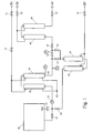
- the figure shows a biowaste treatment apparatus according to the invention.
- the main components provided in the main line of the treatment apparatus in the flow direction of a biowaste-containing liquid are a storage tank 20, a heating unit 30 and a discharge cooling unit 40.
- the treatment apparatus comprises a circulation circuit provided with a circuit cooling unit 50 and connected to the main line, by which circulation circuit the biowaste-containing liquid can be circulated through heating unit 30.
- the biowaste water is conducted into the storage tank through a solid matter separating unit, which is not shown in the figure.
- Storage tank 20 is provided with a mixer 21, and a driving motor 22 connected thereto, by which the biowaste water in the storage tank 20 is mixed to prevent sedimentation in the storage tank 20.
- the storage tank 20 is also provided with a level measurement L.
- heating unit 30 From the storage tank 20 the biowaste water is conducted into heating unit 30 through an inlet valve 13 of the main line by means of a constant capacity feed pump 31.
- heating unit 30 consists of a heat exchanger, in which steam is used as a heat source.
- a sterilization zone 32 is arranged, which herein is provided with two temperature measurements T1 and T2. The measurement of the outlet end T2 is essential, because at that point the lowest temperature occurs.
- the sterilized and deactivated biowaste water is conducted from heating unit 30 into a discharge cooling unit 40 via valve group 14 and 15 which forms a barrier site. From discharge cooling unit 40, the deactivated biowaste water is conducted through main line discharge valve 17 to a sewer system at point A2.
- discharge cooling unit 40 is a heat exchanger using water as a cooling medium.
- the apparatus comprises a return circuit beginning at the barrier site of the main line between sterilization zone 32 and discharge cooling unit 40 and ending at the suction inlet of feed pump 31.
- a first branch is arranged to the first parallel inlet valve 53, and between the first valve 14 and the second valve 15 of the barrier site of the main line, a second outer branch is arranged to a second parallel inlet valve 54.
- Said serial valves 14 and 15 of the main line and said parallel valves 53, 54 of the circulation circuit together form a barrier site.
- the inner branch and outer branch are joined together, whereafter the joined line of the circulation circuit leads to a circuit cooling unit 50 provided in the circulation circuit.
- circuit cooling unit 50 the circulation circuit is closed via circuit discharge valve 55 to a point between main line inlet valve 13 and main line feed pump 31.
- the tightness of the first serial valve 14 can be controlled by means of pressure measurement P coupled to the line between first serial valve 14 and second serial valve 15.
- the cooling water needed in cooling units 40, 50 is brought into circuit cooling unit 50 through cooling water inlet valve 51 at point D1.
- the cooling water circulated in circuit cooling unit 50 is conducted further to discharge cooling unit 40.
- the cooling water circulated in discharge cooling unit 40 is discharged via cooling water discharge valve 52 at point D2.
- the steam needed in heating unit 30 is fed from point E1 30 through first main steam line inlet valve 71 and second inlet valve 72 into heating unit 30.
- the condensate formed in heating unit 30 is discharged at point E2.
- the startup of the apparatus is carried out by self-testing effected by a control system. Thereafter, biowaste is fed into tank 20, and the circulation of the biowaste is started in heating unit 30 at constant speed by means of the circuit, while the temperature of heating unit 30 is raised to the desired level.
- the circulating water is cooled in circuit cooling unit 50 to essentially a level corresponding to the minimum temperature of the water in the storage tank. In this way it is ensured that the load of the heating unit does not exceed its capacity at the beginning of the continuous process.
- valve 14 In the above described startup stage, the integrity of valve 14 is also tested by means of pressure measurement P. If no pressure rise is found by pressure measurement P, valve 14 operates in the desired manner. If as a result of defective tightness of the valve, a pressure rise occurs, it is possible to safely conduct the flow further into the return circuit through the outer branch and valve 53. Thereby valves 14, 15, 53, 54 can be sterilized for maintenance by raising the temperature of the whole circuit to a sufficient level for a sufficient time.
- the circuit can be interrupted by closing valve 53 and opening valve 14, and the deactivated biowaste water can be conducted through discharge cooling means 40 to the sewer system at point A2.
- the sterilization apparatus shown in the figure is controlled by means of a control system or a computer.
- Information on the state and operation of all components shown in the figure are fed into the control system, and on the basis of this information the status of the components as well as of the whole apparatus can be shown on a display.
- the components necessary for understanding the invention are shown, and all other components, e.g. those relating to various measurements, have been left out.
Landscapes
- Life Sciences & Earth Sciences (AREA)
- Health & Medical Sciences (AREA)
- Engineering & Computer Science (AREA)
- Environmental & Geological Engineering (AREA)
- General Health & Medical Sciences (AREA)
- Public Health (AREA)
- Veterinary Medicine (AREA)
- Hydrology & Water Resources (AREA)
- Epidemiology (AREA)
- Animal Behavior & Ethology (AREA)
- Water Supply & Treatment (AREA)
- Chemical & Material Sciences (AREA)
- Organic Chemistry (AREA)
- Apparatus For Disinfection Or Sterilisation (AREA)
- Heat Treatment Of Water, Waste Water Or Sewage (AREA)
- Apparatus Associated With Microorganisms And Enzymes (AREA)
- Processing Of Solid Wastes (AREA)
- Agricultural Chemicals And Associated Chemicals (AREA)
Applications Claiming Priority (3)
| Application Number | Priority Date | Filing Date | Title |
|---|---|---|---|
| FI20011952A FI114020B (fi) | 2001-10-08 | 2001-10-08 | Biojätteen jatkuvatoiminen sterilointilaitteisto ja menetelmä prosessin toimivuuden varmistamiseksi |
| FI20011952 | 2001-10-08 | ||
| PCT/FI2002/000784 WO2003031336A1 (en) | 2001-10-08 | 2002-10-07 | Method and apparatus for the sterilization of biological waste |
Publications (2)
| Publication Number | Publication Date |
|---|---|
| EP1440040A1 EP1440040A1 (en) | 2004-07-28 |
| EP1440040B1 true EP1440040B1 (en) | 2007-01-24 |
Family
ID=8562012
Family Applications (1)
| Application Number | Title | Priority Date | Filing Date |
|---|---|---|---|
| EP02764910A Expired - Lifetime EP1440040B1 (en) | 2001-10-08 | 2002-10-07 | Method and apparatus for the sterilization of biological waste |
Country Status (12)
| Country | Link |
|---|---|
| US (1) | US7211229B2 (enExample) |
| EP (1) | EP1440040B1 (enExample) |
| JP (1) | JP2005504633A (enExample) |
| CN (1) | CN1289406C (enExample) |
| AT (1) | ATE352522T1 (enExample) |
| CA (1) | CA2462592C (enExample) |
| DE (1) | DE60217891T2 (enExample) |
| DK (1) | DK1440040T3 (enExample) |
| ES (1) | ES2281540T3 (enExample) |
| FI (1) | FI114020B (enExample) |
| PT (1) | PT1440040E (enExample) |
| WO (1) | WO2003031336A1 (enExample) |
Families Citing this family (10)
| Publication number | Priority date | Publication date | Assignee | Title |
|---|---|---|---|---|
| US7909895B2 (en) | 2004-11-10 | 2011-03-22 | Enertech Environmental, Inc. | Slurry dewatering and conversion of biosolids to a renewable fuel |
| CA2606319A1 (en) * | 2005-04-27 | 2006-11-09 | Enertech Environmental, Inc. | Organic waste disposal facility and method of disposal |
| FI20105757A0 (fi) | 2010-07-02 | 2010-07-02 | Steris Europe Inc | Lämmön talteenotto biojätteen steriloinnissa |
| ES2358941B2 (es) * | 2010-12-03 | 2012-04-23 | Instalaciones Elur, S.L. | Instalación de acondicionamiento de efluentes líquidos. |
| FI20115350A0 (fi) * | 2011-04-12 | 2011-04-12 | Steris Europe Inc | Laite kiintoaineen erottamiseksi biojätesuspensiosta |
| WO2013054390A1 (ja) * | 2011-10-11 | 2013-04-18 | 鹿島建設株式会社 | 排水の不活化方法及びシステム |
| AU2013201567B2 (en) * | 2012-11-28 | 2015-12-17 | Gambro Lundia Ab | Systems, apparatus, equipment with thermal disinfection and thermal disinfection methods |
| EP3354286A1 (en) * | 2017-01-30 | 2018-08-01 | Bayer Healthcare LLC | Non-sterile waste removal from a sterile process |
| US10343933B1 (en) * | 2018-11-17 | 2019-07-09 | John Guy Bowen | Self priming and evacuating liquid sterilizing system |
| CN117605957A (zh) * | 2023-11-17 | 2024-02-27 | 湖南中联重科应急装备有限公司 | 用于洗消系统的控制方法、洗消系统、存储介质及处理器 |
Family Cites Families (6)
| Publication number | Priority date | Publication date | Assignee | Title |
|---|---|---|---|---|
| GB1053249A (enExample) * | 1962-10-18 | |||
| US3986955A (en) * | 1975-01-28 | 1976-10-19 | Sphere, Incorporated | Effluent waste treatment process and apparatus |
| DE3887504D1 (de) * | 1987-10-23 | 1994-03-10 | Vaillant Joh Gmbh & Co | Einrichtung zur verhinderung des auftretens bzw. der fortpflanzung von kleinstlebewesen in brauchwasser. |
| DE59004177D1 (de) * | 1989-04-06 | 1994-02-24 | Vaillant Joh Gmbh & Co | Verfahren zum Desinfizieren einer Brauchwasseranlage. |
| AU764282B2 (en) * | 1999-03-30 | 2003-08-14 | Gambro Lundia Ab | Method and apparatus for sterilising a heat sensitive fluid |
| US6521133B1 (en) * | 2000-08-07 | 2003-02-18 | Roediger Pittsburgh, Inc. | Process for thermal sludge disinfection |
-
2001
- 2001-10-08 FI FI20011952A patent/FI114020B/fi active
-
2002
- 2002-10-07 DE DE60217891T patent/DE60217891T2/de not_active Expired - Lifetime
- 2002-10-07 ES ES02764910T patent/ES2281540T3/es not_active Expired - Lifetime
- 2002-10-07 DK DK02764910T patent/DK1440040T3/da active
- 2002-10-07 CN CNB028199499A patent/CN1289406C/zh not_active Expired - Fee Related
- 2002-10-07 US US10/491,765 patent/US7211229B2/en not_active Expired - Lifetime
- 2002-10-07 JP JP2003534326A patent/JP2005504633A/ja active Pending
- 2002-10-07 AT AT02764910T patent/ATE352522T1/de not_active IP Right Cessation
- 2002-10-07 CA CA2462592A patent/CA2462592C/en not_active Expired - Fee Related
- 2002-10-07 PT PT02764910T patent/PT1440040E/pt unknown
- 2002-10-07 WO PCT/FI2002/000784 patent/WO2003031336A1/en not_active Ceased
- 2002-10-07 EP EP02764910A patent/EP1440040B1/en not_active Expired - Lifetime
Also Published As
| Publication number | Publication date |
|---|---|
| PT1440040E (pt) | 2007-04-30 |
| DE60217891D1 (de) | 2007-03-15 |
| FI20011952A0 (fi) | 2001-10-08 |
| FI114020B (fi) | 2004-07-30 |
| ATE352522T1 (de) | 2007-02-15 |
| US7211229B2 (en) | 2007-05-01 |
| ES2281540T3 (es) | 2007-10-01 |
| CA2462592C (en) | 2011-05-10 |
| JP2005504633A (ja) | 2005-02-17 |
| WO2003031336A1 (en) | 2003-04-17 |
| EP1440040A1 (en) | 2004-07-28 |
| DK1440040T3 (da) | 2007-11-26 |
| CA2462592A1 (en) | 2003-04-17 |
| US20050002824A1 (en) | 2005-01-06 |
| CN1568289A (zh) | 2005-01-19 |
| CN1289406C (zh) | 2006-12-13 |
| FI20011952L (fi) | 2003-04-09 |
| DE60217891T2 (de) | 2007-06-21 |
Similar Documents
| Publication | Publication Date | Title |
|---|---|---|
| EP1440040B1 (en) | Method and apparatus for the sterilization of biological waste | |
| CA2658865C (en) | Filter assembly for a reprocessor | |
| US5906800A (en) | Steam delivery system for a decontamination apparatus | |
| US8325049B2 (en) | Method and system for measuring temperature and pressure in different regions to determine steam quality | |
| US9108872B2 (en) | Solids separator and method of treatment for biowaste | |
| CN1068178C (zh) | 牛奶和奶油类流体连续消毒装置 | |
| AU2002329302B2 (en) | Method and apparatus for the sterilization of biological waste | |
| AU2002329302A1 (en) | Method and apparatus for the sterilization of biological waste | |
| CN220981523U (zh) | 一种车间消毒系统 | |
| US8961874B2 (en) | Heat recovery in biowaste sterilization | |
| US20070131603A1 (en) | Effluent sterilizer system | |
| JP3676728B2 (ja) | 排水の加熱滅菌方法及び装置 | |
| JP3919161B2 (ja) | 被処理液の加熱滅菌方法及び装置 | |
| US11926535B2 (en) | Decontamination apparatus for effluents | |
| JPH10180241A (ja) | 医療排水処理システム | |
| EP0705608A1 (de) | Anlage zum Sterilisieren und/oder Desinfizieren pump- oder rieselfähiger Medien | |
| JP3225139B2 (ja) | 殺菌装置における点検装置 | |
| CA2529608A1 (en) | Effluent sterilizer system |
Legal Events
| Date | Code | Title | Description |
|---|---|---|---|
| PUAI | Public reference made under article 153(3) epc to a published international application that has entered the european phase |
Free format text: ORIGINAL CODE: 0009012 |
|
| 17P | Request for examination filed |
Effective date: 20040410 |
|
| AK | Designated contracting states |
Kind code of ref document: A1 Designated state(s): AT BE BG CH CY CZ DE DK EE ES FI FR GB GR IE IT LI LU MC NL PT SE SK TR |
|
| AX | Request for extension of the european patent |
Extension state: AL LT LV MK RO SI |
|
| RIN1 | Information on inventor provided before grant (corrected) |
Inventor name: SALMISUO, MAURI Inventor name: NURMINEN, TEPPO Inventor name: HAELLI, RIKU Inventor name: MATTILA, JUHA |
|
| GRAP | Despatch of communication of intention to grant a patent |
Free format text: ORIGINAL CODE: EPIDOSNIGR1 |
|
| GRAS | Grant fee paid |
Free format text: ORIGINAL CODE: EPIDOSNIGR3 |
|
| GRAA | (expected) grant |
Free format text: ORIGINAL CODE: 0009210 |
|
| AK | Designated contracting states |
Kind code of ref document: B1 Designated state(s): AT BE BG CH CY CZ DE DK EE ES FI FR GB GR IE IT LI LU MC NL PT SE SK TR |
|
| PG25 | Lapsed in a contracting state [announced via postgrant information from national office to epo] |
Ref country code: FI Free format text: LAPSE BECAUSE OF FAILURE TO SUBMIT A TRANSLATION OF THE DESCRIPTION OR TO PAY THE FEE WITHIN THE PRESCRIBED TIME-LIMIT Effective date: 20070124 |
|
| REG | Reference to a national code |
Ref country code: GB Ref legal event code: FG4D |
|
| REG | Reference to a national code |
Ref country code: CH Ref legal event code: EP |
|
| REG | Reference to a national code |
Ref country code: IE Ref legal event code: FG4D |
|
| REF | Corresponds to: |
Ref document number: 60217891 Country of ref document: DE Date of ref document: 20070315 Kind code of ref document: P |
|
| PG25 | Lapsed in a contracting state [announced via postgrant information from national office to epo] |
Ref country code: BG Free format text: LAPSE BECAUSE OF THE APPLICANT RENOUNCES Effective date: 20070425 |
|
| REG | Reference to a national code |
Ref country code: PT Ref legal event code: SC4A Free format text: AVAILABILITY OF NATIONAL TRANSLATION Effective date: 20070329 |
|
| REG | Reference to a national code |
Ref country code: SE Ref legal event code: TRGR |
|
| REG | Reference to a national code |
Ref country code: CH Ref legal event code: NV Representative=s name: BOVARD AG PATENTANWAELTE |
|
| ET | Fr: translation filed | ||
| REG | Reference to a national code |
Ref country code: ES Ref legal event code: FG2A Ref document number: 2281540 Country of ref document: ES Kind code of ref document: T3 |
|
| PG25 | Lapsed in a contracting state [announced via postgrant information from national office to epo] |
Ref country code: SK Free format text: LAPSE BECAUSE OF FAILURE TO SUBMIT A TRANSLATION OF THE DESCRIPTION OR TO PAY THE FEE WITHIN THE PRESCRIBED TIME-LIMIT Effective date: 20070124 |
|
| REG | Reference to a national code |
Ref country code: DK Ref legal event code: T3 |
|
| PLBE | No opposition filed within time limit |
Free format text: ORIGINAL CODE: 0009261 |
|
| STAA | Information on the status of an ep patent application or granted ep patent |
Free format text: STATUS: NO OPPOSITION FILED WITHIN TIME LIMIT |
|
| 26N | No opposition filed |
Effective date: 20071025 |
|
| PG25 | Lapsed in a contracting state [announced via postgrant information from national office to epo] |
Ref country code: CZ Free format text: LAPSE BECAUSE OF FAILURE TO SUBMIT A TRANSLATION OF THE DESCRIPTION OR TO PAY THE FEE WITHIN THE PRESCRIBED TIME-LIMIT Effective date: 20070124 |
|
| PGFP | Annual fee paid to national office [announced via postgrant information from national office to epo] |
Ref country code: DK Payment date: 20071031 Year of fee payment: 6 Ref country code: NL Payment date: 20071024 Year of fee payment: 6 |
|
| PGFP | Annual fee paid to national office [announced via postgrant information from national office to epo] |
Ref country code: AT Payment date: 20070919 Year of fee payment: 6 Ref country code: CH Payment date: 20071030 Year of fee payment: 6 |
|
| PGFP | Annual fee paid to national office [announced via postgrant information from national office to epo] |
Ref country code: SE Payment date: 20071029 Year of fee payment: 6 Ref country code: BE Payment date: 20071107 Year of fee payment: 6 |
|
| PG25 | Lapsed in a contracting state [announced via postgrant information from national office to epo] |
Ref country code: GR Free format text: LAPSE BECAUSE OF FAILURE TO SUBMIT A TRANSLATION OF THE DESCRIPTION OR TO PAY THE FEE WITHIN THE PRESCRIBED TIME-LIMIT Effective date: 20070425 |
|
| PG25 | Lapsed in a contracting state [announced via postgrant information from national office to epo] |
Ref country code: MC Free format text: LAPSE BECAUSE OF NON-PAYMENT OF DUE FEES Effective date: 20071031 |
|
| PG25 | Lapsed in a contracting state [announced via postgrant information from national office to epo] |
Ref country code: EE Free format text: LAPSE BECAUSE OF FAILURE TO SUBMIT A TRANSLATION OF THE DESCRIPTION OR TO PAY THE FEE WITHIN THE PRESCRIBED TIME-LIMIT Effective date: 20070124 |
|
| REG | Reference to a national code |
Ref country code: PT Ref legal event code: MM4A Free format text: LAPSE DUE TO NON-PAYMENT OF FEES Effective date: 20090407 |
|
| BERE | Be: lapsed |
Owner name: STERIS EUROPE, INC. SUOMEN SIVULIIKE Effective date: 20081031 |
|
| REG | Reference to a national code |
Ref country code: CH Ref legal event code: PL |
|
| REG | Reference to a national code |
Ref country code: DK Ref legal event code: EBP |
|
| EUG | Se: european patent has lapsed | ||
| NLV4 | Nl: lapsed or anulled due to non-payment of the annual fee |
Effective date: 20090501 |
|
| PG25 | Lapsed in a contracting state [announced via postgrant information from national office to epo] |
Ref country code: NL Free format text: LAPSE BECAUSE OF NON-PAYMENT OF DUE FEES Effective date: 20090501 Ref country code: CY Free format text: LAPSE BECAUSE OF FAILURE TO SUBMIT A TRANSLATION OF THE DESCRIPTION OR TO PAY THE FEE WITHIN THE PRESCRIBED TIME-LIMIT Effective date: 20070124 |
|
| PG25 | Lapsed in a contracting state [announced via postgrant information from national office to epo] |
Ref country code: AT Free format text: LAPSE BECAUSE OF NON-PAYMENT OF DUE FEES Effective date: 20081007 Ref country code: PT Free format text: LAPSE BECAUSE OF NON-PAYMENT OF DUE FEES Effective date: 20090407 Ref country code: LU Free format text: LAPSE BECAUSE OF NON-PAYMENT OF DUE FEES Effective date: 20071007 |
|
| PGFP | Annual fee paid to national office [announced via postgrant information from national office to epo] |
Ref country code: IE Payment date: 20071025 Year of fee payment: 6 |
|
| PG25 | Lapsed in a contracting state [announced via postgrant information from national office to epo] |
Ref country code: TR Free format text: LAPSE BECAUSE OF FAILURE TO SUBMIT A TRANSLATION OF THE DESCRIPTION OR TO PAY THE FEE WITHIN THE PRESCRIBED TIME-LIMIT Effective date: 20070124 Ref country code: BE Free format text: LAPSE BECAUSE OF NON-PAYMENT OF DUE FEES Effective date: 20081031 |
|
| PG25 | Lapsed in a contracting state [announced via postgrant information from national office to epo] |
Ref country code: IE Free format text: LAPSE BECAUSE OF NON-PAYMENT OF DUE FEES Effective date: 20081007 Ref country code: DK Free format text: LAPSE BECAUSE OF NON-PAYMENT OF DUE FEES Effective date: 20081031 Ref country code: LI Free format text: LAPSE BECAUSE OF NON-PAYMENT OF DUE FEES Effective date: 20081031 Ref country code: CH Free format text: LAPSE BECAUSE OF NON-PAYMENT OF DUE FEES Effective date: 20081031 |
|
| PGFP | Annual fee paid to national office [announced via postgrant information from national office to epo] |
Ref country code: PT Payment date: 20070920 Year of fee payment: 6 |
|
| PG25 | Lapsed in a contracting state [announced via postgrant information from national office to epo] |
Ref country code: SE Free format text: LAPSE BECAUSE OF NON-PAYMENT OF DUE FEES Effective date: 20081008 |
|
| REG | Reference to a national code |
Ref country code: FR Ref legal event code: PLFP Year of fee payment: 14 |
|
| REG | Reference to a national code |
Ref country code: FR Ref legal event code: PLFP Year of fee payment: 15 |
|
| REG | Reference to a national code |
Ref country code: FR Ref legal event code: PLFP Year of fee payment: 16 |
|
| REG | Reference to a national code |
Ref country code: FR Ref legal event code: PLFP Year of fee payment: 17 |
|
| PGFP | Annual fee paid to national office [announced via postgrant information from national office to epo] |
Ref country code: DE Payment date: 20181029 Year of fee payment: 17 |
|
| PGFP | Annual fee paid to national office [announced via postgrant information from national office to epo] |
Ref country code: IT Payment date: 20181023 Year of fee payment: 17 Ref country code: ES Payment date: 20181102 Year of fee payment: 17 Ref country code: FR Payment date: 20181025 Year of fee payment: 17 Ref country code: GB Payment date: 20181029 Year of fee payment: 17 |
|
| REG | Reference to a national code |
Ref country code: DE Ref legal event code: R119 Ref document number: 60217891 Country of ref document: DE |
|
| PG25 | Lapsed in a contracting state [announced via postgrant information from national office to epo] |
Ref country code: DE Free format text: LAPSE BECAUSE OF NON-PAYMENT OF DUE FEES Effective date: 20200501 |
|
| GBPC | Gb: european patent ceased through non-payment of renewal fee |
Effective date: 20191007 |
|
| PG25 | Lapsed in a contracting state [announced via postgrant information from national office to epo] |
Ref country code: FR Free format text: LAPSE BECAUSE OF NON-PAYMENT OF DUE FEES Effective date: 20191031 Ref country code: GB Free format text: LAPSE BECAUSE OF NON-PAYMENT OF DUE FEES Effective date: 20191007 Ref country code: IT Free format text: LAPSE BECAUSE OF NON-PAYMENT OF DUE FEES Effective date: 20191007 |
|
| REG | Reference to a national code |
Ref country code: ES Ref legal event code: FD2A Effective date: 20210302 |
|
| PG25 | Lapsed in a contracting state [announced via postgrant information from national office to epo] |
Ref country code: ES Free format text: LAPSE BECAUSE OF NON-PAYMENT OF DUE FEES Effective date: 20191008 |