EP1439631A2 - Verfahren und Vorrichtung zur Energiegewinnung - Google Patents
Verfahren und Vorrichtung zur Energiegewinnung Download PDFInfo
- Publication number
- EP1439631A2 EP1439631A2 EP04386001A EP04386001A EP1439631A2 EP 1439631 A2 EP1439631 A2 EP 1439631A2 EP 04386001 A EP04386001 A EP 04386001A EP 04386001 A EP04386001 A EP 04386001A EP 1439631 A2 EP1439631 A2 EP 1439631A2
- Authority
- EP
- European Patent Office
- Prior art keywords
- energy
- production
- wheels
- rings
- torque
- Prior art date
- Legal status (The legal status is an assumption and is not a legal conclusion. Google has not performed a legal analysis and makes no representation as to the accuracy of the status listed.)
- Withdrawn
Links
Images

Classifications
-
- H—ELECTRICITY
- H02—GENERATION; CONVERSION OR DISTRIBUTION OF ELECTRIC POWER
- H02K—DYNAMO-ELECTRIC MACHINES
- H02K53/00—Alleged dynamo-electric perpetua mobilia
-
- F—MECHANICAL ENGINEERING; LIGHTING; HEATING; WEAPONS; BLASTING
- F03—MACHINES OR ENGINES FOR LIQUIDS; WIND, SPRING, OR WEIGHT MOTORS; PRODUCING MECHANICAL POWER OR A REACTIVE PROPULSIVE THRUST, NOT OTHERWISE PROVIDED FOR
- F03G—SPRING, WEIGHT, INERTIA OR LIKE MOTORS; MECHANICAL-POWER PRODUCING DEVICES OR MECHANISMS, NOT OTHERWISE PROVIDED FOR OR USING ENERGY SOURCES NOT OTHERWISE PROVIDED FOR
- F03G7/00—Mechanical-power-producing mechanisms, not otherwise provided for or using energy sources not otherwise provided for
-
- F—MECHANICAL ENGINEERING; LIGHTING; HEATING; WEAPONS; BLASTING
- F05—INDEXING SCHEMES RELATING TO ENGINES OR PUMPS IN VARIOUS SUBCLASSES OF CLASSES F01-F04
- F05B—INDEXING SCHEME RELATING TO WIND, SPRING, WEIGHT, INERTIA OR LIKE MOTORS, TO MACHINES OR ENGINES FOR LIQUIDS COVERED BY SUBCLASSES F03B, F03D AND F03G
- F05B2260/00—Function
- F05B2260/40—Transmission of power
- F05B2260/403—Transmission of power through the shape of the drive components
- F05B2260/4031—Transmission of power through the shape of the drive components as in toothed gearing
- F05B2260/40311—Transmission of power through the shape of the drive components as in toothed gearing of the epicyclic, planetary or differential type
-
- H—ELECTRICITY
- H02—GENERATION; CONVERSION OR DISTRIBUTION OF ELECTRIC POWER
- H02K—DYNAMO-ELECTRIC MACHINES
- H02K7/00—Arrangements for handling mechanical energy structurally associated with dynamo-electric machines, e.g. structural association with mechanical driving motors or auxiliary dynamo-electric machines
- H02K7/10—Structural association with clutches, brakes, gears, pulleys or mechanical starters
- H02K7/116—Structural association with clutches, brakes, gears, pulleys or mechanical starters with gears
Definitions
- the present invention relates to the field of the art of methods, means and mechanisms for the production of energy at an extremely high efficiency and more specifically it proposes a method and a mechanism based in the simultaneous exploitation of an action exerted on a system and of the reaction being associated with that action, wherein the proposed method and mechanism succeed in producing energy with a controlled and adjustable with an absolute accuracy at a desired predetermined level, torque and power output.
- the object of the present invention to advantageously overcome the disadvantages and drawbacks of the prior art and propose a method and mechanism, the employment of which will lead to advantageously overcoming the disadvantages and drawbacks of the prior art and to ensuring the production of energy with a high efficiency, wherein the proposed method and mechanism are based on the theory of a simultaneous exploitation of the action exerted on a system and of the reaction produced thereby and wherein the proposed method and mechanism achieve the production of energy with controlled, adjustable with an absolute precision at a desirable predetermined level, parameters of torque and motive power.
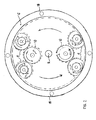
- the device of the invention includes sequential steps of transformation of motion, constituted from flywheels, series of toothed wheels (gears) with suitably selected accessories, such as bearings, spacers, wedges, etc., all of which are arranged in the perimeter of a central principal shaft 2.
- the device of the invention is put in operation when by means of any desirable, conventional and known in the prior art, suitable and available mode and means, is provided a certain quantity of initial energy, e.g. from the power supplying motor that is not depicted.
- Three sequential flywheel units 3, 4, 5 are mounted along the principal central axis 2 of the device in between the bottom basement 1 and the upper cover 15 thereof.
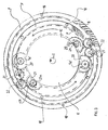
- Three rings 6, 7 and 8 are mounted, again from the bottom to the top of central shaft 2, having progressively increasing diameters, so that the diameter of fixedly mounted ring 8 is bigger than that of ring 7 and the diameter of ring 7 is bigger than that of ring 6.
- the three rings are mounted in the circumference of the device, being fixedly mounted via suitable pillars 18 in the basement 1 of the device. All three fixedly mounted rings 6, 7 and 8 are provided with a circumferential internal toothing.
- the power supply motor that is not portrayed in the drawings is engaged with the denture of the first bottom flywheel 3.
- the kinetic energy is thereby transferred from flywheel 3 on the one hand in the series of double toothed wheels 9 that are pivotally mounted within suitable bearings and on the other hand in the shafts 13 of flywheel 4 extending on either side of the principal shaft 2 of the device.
- each pair of wheels 9 corresponds an underlying wheel 9a of smaller diameter, wherein the wheels 9a are engaged in the circumferential first fixed ring 6 and, as it appears in Fig. 2, two such series of double toothed wheels 9 are arranged in diametrically opposing positions in the perimeter of ring 6.
- two such series of double toothed wheels 9 are arranged in diametrically opposing positions in the perimeter of ring 6.
- Wheels 25 move in the circumference of the fixed wheel with external denture 11, whilst the wheels 25a engaged in the wheel 11 a of the generator shaft 26 supply the energy required by the system.
- wheels 10 being engaged with wheels 9 result in the increase of torque in the shafts 19 of wheels 9 ⁇ 9a, as the wheels 9a move around the circumference of the first fixed ring 6 and they simultaneously perform a rotation around their own axis.
- wheels 9a' and 20 that lie above the wheels 9-9a along the same axis with the latter to wheels that are engaged with the third fixed ring with internal denture 8.
- wheels 9a' having the same diameter as the wheels 9a, are engaged to the second internally toothed fixed ring 7 and move around the circumference thereof, thereby providing the torque increased during the second stage to the overlying wheels of bigger diameter 20.
- free toothed wheels 21 that transfer the motion in the wheels 22 that have the same diameter and move around the circumference of the third internally toothed fixed ring 8, providing a resultant still further increased torque.
- the device of the invention was tried in operation by the Swedish company V ⁇ STKUSTKRAFT AB.
- the measuring instrumentation used in the test was equipped with an electric motor, of the asynchronous 3-phase and of a nominal capacity 2.25 kVA type.
- the motor was connected in series with an on-off switch and starter with a three phase durable adjustable resistor of 3.0 kVA.
- the electric energy was supplied through a suitable voltage potentiometer with a safety fuse 3X20 A, connected through a D form quadrapolar conductive wire.
- a single phase synchronous self magnetized generator of an optimum capacity of 1.5 KVA at 3000 revs was mounted onto the output shaft.
- the Measurement was carried out only in the engine, not including the rheostatic resistance.
- the measuring instrument Fluke 43 was used for the recordal of voltage and current. This instrument records these parameters, as well as the frequency and the intermediate - transitory produced parameters and it displays all the electric parameters, that are essential and relevant in the framework of the measurement and specific order to the testing company V ⁇ STKUSTKRAFT AB.
- the instrument was put in operation and measurements were carried out three times. It was the third time that the maximum revs amounting to 95% of the nominal value at 50 Hz was recorded in the resulting output. This corresponds in a number of revs at the generator of the order of 2.850 rpm.
- the device did not present any problem during these measurements, but the number of revs was decreased for the sake of safety of those present and for avoiding damages being produced in the invented device.
- the device was put in operation, but the measurement stopped after 17 seconds as the frequency of 28.8 Hz was reached, in order to correct a calibration problem encountered with the measuring instrument FLUKE 43.
- the device was put in operation and the number of revs was continuously increased up to a value close to approximately 95% of the total number of revs that could be reached by a synchronous generator. At a value of approximately 62% of the nominal number of revs a voltage was measured at the generator that started to supply energy to the load imposed to the device. This was manifested more clearly when the noise of the instrument became more intense.
- the rheostatic resistance was regulated also for higher voltage values, so that the number of revs would not need to be decreased.
- the first measurement was recorded at the 89% of the total number of revs. At the 95% of the total number of revs of the generator, the power produced was logarithmically increased and it was at this rpm value that 0.77 kW was produced. The power supplied at this instant was 0.77 kW. Such measurement is remarkable of course if one takes into account the expected losses of the device itself.
- the device entered in operation the number of revs was increased and energy was produced by the generator.
- the power produced by the generator was 0.92 kW at cos ⁇ 1.0.
- the power input at this particular moment was 0.88 kW.
- the measurement lasted 94 seconds, as long as it was judged advisable in order to avoid any danger for those present in the test procedure.
- the 95% of the total number of revs was kept constant for a period of 32 seconds. Throughout these 32 seconds the power output was higher than the power input.
Landscapes
- Engineering & Computer Science (AREA)
- Chemical & Material Sciences (AREA)
- Combustion & Propulsion (AREA)
- Power Engineering (AREA)
- Mechanical Engineering (AREA)
- General Engineering & Computer Science (AREA)
- Connection Of Motors, Electrical Generators, Mechanical Devices, And The Like (AREA)
- Retarders (AREA)
Applications Claiming Priority (2)
| Application Number | Priority Date | Filing Date | Title |
|---|---|---|---|
| GR20030100013A GR1004373B (el) | 2003-01-14 | 2003-01-14 | Μεθοδος και μηχανισμος αναπαραγωγης ενεργειας |
| GR2003100013 | 2003-01-14 |
Publications (2)
| Publication Number | Publication Date |
|---|---|
| EP1439631A2 true EP1439631A2 (de) | 2004-07-21 |
| EP1439631A3 EP1439631A3 (de) | 2006-12-06 |
Family
ID=29559962
Family Applications (1)
| Application Number | Title | Priority Date | Filing Date |
|---|---|---|---|
| EP04386001A Withdrawn EP1439631A3 (de) | 2003-01-14 | 2004-01-08 | Verfahren und Vorrichtung zur Energiegewinnung |
Country Status (2)
| Country | Link |
|---|---|
| EP (1) | EP1439631A3 (de) |
| GR (1) | GR1004373B (de) |
Cited By (8)
| Publication number | Priority date | Publication date | Assignee | Title |
|---|---|---|---|---|
| WO2006106375A1 (en) * | 2005-04-04 | 2006-10-12 | Tantris Ltd | Device for non reactive propulsion generated from eccentric motions |
| WO2008032133A1 (en) * | 2005-08-17 | 2008-03-20 | Jayantha Liyanage | The dual drive electric regenerator |
| WO2008037014A1 (en) * | 2006-09-29 | 2008-04-03 | Universal Engines Pty Ltd | Force amplification method and apparatus by the harnessing of centrifugal force |
| WO2010147450A1 (en) * | 2009-06-17 | 2010-12-23 | Green-Tech Holdings Sdn Bhd | Uninterrupted battery operated generator system |
| ITAV20100003A1 (it) * | 2010-07-30 | 2012-01-31 | Michele Masiello | "innovativo dispositivo meccanico che, grazie ad una serie di ingranaggi di diverso diametro, alcuni volani per l'accumulo dell'energia e un grande satellite impiegato come leva, genera lavoro" |
| WO2015003205A1 (en) * | 2013-07-07 | 2015-01-15 | Universal Engines Pty Ltd | Self powering energy generation by the harnessing of centrifugal force |
| WO2019091272A1 (zh) * | 2017-11-07 | 2019-05-16 | 张志军 | 梯度差量式永磁驱动器 |
| WO2023130154A1 (en) * | 2022-01-07 | 2023-07-13 | Geoffrey William Good Leviny | Energy generator |
Family Cites Families (5)
| Publication number | Priority date | Publication date | Assignee | Title |
|---|---|---|---|---|
| JPS5635676A (en) * | 1979-08-27 | 1981-04-08 | Mitsuaki Inagaki | Electric generator |
| JPH08256470A (ja) * | 1993-04-12 | 1996-10-01 | Takashi Nosaka | 回転力増幅装置とその電動機及びその発電装置。 |
| EP1293029A1 (de) * | 2000-06-20 | 2003-03-19 | Alexander Ellison Rees | Elektrische transmission |
| US6433450B1 (en) * | 2000-11-28 | 2002-08-13 | Wen-Ping Chao | Power generating system with physical energy to enhance output |
| DE10208059A1 (de) * | 2001-05-02 | 2002-10-24 | David Evince O'lucky | Elektrisch Verstärkungs- Generator (genannt EVG), für Haushalt- und Industrienutzung geeignet |
-
2003
- 2003-01-14 GR GR20030100013A patent/GR1004373B/el unknown
-
2004
- 2004-01-08 EP EP04386001A patent/EP1439631A3/de not_active Withdrawn
Cited By (9)
| Publication number | Priority date | Publication date | Assignee | Title |
|---|---|---|---|---|
| WO2006106375A1 (en) * | 2005-04-04 | 2006-10-12 | Tantris Ltd | Device for non reactive propulsion generated from eccentric motions |
| WO2008032133A1 (en) * | 2005-08-17 | 2008-03-20 | Jayantha Liyanage | The dual drive electric regenerator |
| AU2006348382B2 (en) * | 2005-08-17 | 2013-04-18 | Jayantha Liyanage | The dual drive electric regenerator |
| WO2008037014A1 (en) * | 2006-09-29 | 2008-04-03 | Universal Engines Pty Ltd | Force amplification method and apparatus by the harnessing of centrifugal force |
| WO2010147450A1 (en) * | 2009-06-17 | 2010-12-23 | Green-Tech Holdings Sdn Bhd | Uninterrupted battery operated generator system |
| ITAV20100003A1 (it) * | 2010-07-30 | 2012-01-31 | Michele Masiello | "innovativo dispositivo meccanico che, grazie ad una serie di ingranaggi di diverso diametro, alcuni volani per l'accumulo dell'energia e un grande satellite impiegato come leva, genera lavoro" |
| WO2015003205A1 (en) * | 2013-07-07 | 2015-01-15 | Universal Engines Pty Ltd | Self powering energy generation by the harnessing of centrifugal force |
| WO2019091272A1 (zh) * | 2017-11-07 | 2019-05-16 | 张志军 | 梯度差量式永磁驱动器 |
| WO2023130154A1 (en) * | 2022-01-07 | 2023-07-13 | Geoffrey William Good Leviny | Energy generator |
Also Published As
| Publication number | Publication date |
|---|---|
| GR1004373B (el) | 2003-10-23 |
| EP1439631A3 (de) | 2006-12-06 |
Similar Documents
| Publication | Publication Date | Title |
|---|---|---|
| US6731017B2 (en) | Distributed powertrain that increases electric power generator density | |
| RU2423716C2 (ru) | Способ и устройство контроля механизма | |
| US6239524B1 (en) | Power conversion methods and apparatus | |
| AU2006200782A1 (en) | Methods and apparatus for pitch control power conversion | |
| US8049353B1 (en) | Stackable generator arrangement | |
| EP1439631A2 (de) | Verfahren und Vorrichtung zur Energiegewinnung | |
| JP7146580B2 (ja) | 風力発電装置及び風力発電システム | |
| RU2737738C1 (ru) | Стенд для испытания электроприводов | |
| ES2555067T3 (es) | Instalación de ensayo y método para ensayar cajas de engranajes y convertidores de energía electromecánicos | |
| CN209444758U (zh) | 一种直驱式谐波减速器传动装置 | |
| US10844944B2 (en) | Inverted harmonic gear actuator | |
| US20160201652A1 (en) | System and method for integrating a horizontal axis wind turbine and a vertical axis wind turbine | |
| CA2589083C (en) | Mechanical system for power change between the input and output thereof | |
| CN201541175U (zh) | 自然力发电设备及发电机组 | |
| CN102025220B (zh) | 自然力发电设备及发电机组 | |
| JP2021019500A (ja) | 動力伝達装置 | |
| US8517669B2 (en) | Mechanical wind turbine and method of use | |
| CN102418674B (zh) | 储能风力发电装置 | |
| CN106712688B (zh) | 一种安全可靠的高效太阳能发电装置 | |
| BR112023005785A2 (pt) | Sistema de transmissão de potência de turbina eólica | |
| SU1796044A3 (ru) | Mhoгoпotoчhый дbуxctупehчatый peдуktop oпopho-tpahcmиccиohhoгo узлa betpoэhepгetичeckoй уctahobkи | |
| WO2008053494A1 (en) | An engine to convert gravitational energy into electrical energy | |
| JP2006144598A (ja) | ウインドタービン装置増速装置 | |
| CN207513690U (zh) | 燃气轮机发电机组及其连接结构 | |
| CN203756873U (zh) | 一种行星差环减速器 |
Legal Events
| Date | Code | Title | Description |
|---|---|---|---|
| PUAI | Public reference made under article 153(3) epc to a published international application that has entered the european phase |
Free format text: ORIGINAL CODE: 0009012 |
|
| AK | Designated contracting states |
Kind code of ref document: A2 Designated state(s): AT BE BG CH CY CZ DE DK EE ES FI FR GB GR HU IE IT LI LU MC NL PT RO SE SI SK TR |
|
| AX | Request for extension of the european patent |
Extension state: AL HR LT LV MK |
|
| 17P | Request for examination filed |
Effective date: 20050120 |
|
| PUAL | Search report despatched |
Free format text: ORIGINAL CODE: 0009013 |
|
| AK | Designated contracting states |
Kind code of ref document: A3 Designated state(s): AT BE BG CH CY CZ DE DK EE ES FI FR GB GR HU IE IT LI LU MC NL PT RO SE SI SK TR |
|
| AX | Request for extension of the european patent |
Extension state: AL LT LV MK |
|
| AKX | Designation fees paid |
Designated state(s): AT BE BG CH CY CZ DE DK EE ES FI FR GB GR HU IE IT LI LU MC NL PT RO SE SI SK TR |
|
| STAA | Information on the status of an ep patent application or granted ep patent |
Free format text: STATUS: THE APPLICATION IS DEEMED TO BE WITHDRAWN |
|
| 18D | Application deemed to be withdrawn |
Effective date: 20120801 |