EP1439319A1 - Schichtfeder und Verfahren zu seiner Herstellung - Google Patents
Schichtfeder und Verfahren zu seiner Herstellung Download PDFInfo
- Publication number
- EP1439319A1 EP1439319A1 EP03026201A EP03026201A EP1439319A1 EP 1439319 A1 EP1439319 A1 EP 1439319A1 EP 03026201 A EP03026201 A EP 03026201A EP 03026201 A EP03026201 A EP 03026201A EP 1439319 A1 EP1439319 A1 EP 1439319A1
- Authority
- EP
- European Patent Office
- Prior art keywords
- layer
- elastomer
- layer spring
- inserts
- spring
- Prior art date
- Legal status (The legal status is an assumption and is not a legal conclusion. Google has not performed a legal analysis and makes no representation as to the accuracy of the status listed.)
- Granted
Links
- 238000004519 manufacturing process Methods 0.000 title claims abstract description 15
- 229920001971 elastomer Polymers 0.000 claims abstract description 29
- 239000000806 elastomer Substances 0.000 claims abstract description 29
- 239000000463 material Substances 0.000 claims description 4
- 238000004073 vulcanization Methods 0.000 claims description 4
- 238000002347 injection Methods 0.000 claims description 2
- 239000007924 injection Substances 0.000 claims description 2
- 229910052751 metal Inorganic materials 0.000 abstract description 15
- 239000002184 metal Substances 0.000 abstract description 14
- 238000005516 engineering process Methods 0.000 description 2
- 239000000203 mixture Substances 0.000 description 2
- 230000015572 biosynthetic process Effects 0.000 description 1
- 239000002131 composite material Substances 0.000 description 1
- 238000010276 construction Methods 0.000 description 1
- 239000003292 glue Substances 0.000 description 1
- 230000000704 physical effect Effects 0.000 description 1
- 239000000243 solution Substances 0.000 description 1
- 239000000126 substance Substances 0.000 description 1
- 239000000725 suspension Substances 0.000 description 1
Images


Classifications
-
- F—MECHANICAL ENGINEERING; LIGHTING; HEATING; WEAPONS; BLASTING
- F16—ENGINEERING ELEMENTS AND UNITS; GENERAL MEASURES FOR PRODUCING AND MAINTAINING EFFECTIVE FUNCTIONING OF MACHINES OR INSTALLATIONS; THERMAL INSULATION IN GENERAL
- F16F—SPRINGS; SHOCK-ABSORBERS; MEANS FOR DAMPING VIBRATION
- F16F1/00—Springs
- F16F1/36—Springs made of rubber or other material having high internal friction, e.g. thermoplastic elastomers
- F16F1/40—Springs made of rubber or other material having high internal friction, e.g. thermoplastic elastomers consisting of a stack of similar elements separated by non-elastic intermediate layers
- F16F1/41—Springs made of rubber or other material having high internal friction, e.g. thermoplastic elastomers consisting of a stack of similar elements separated by non-elastic intermediate layers the spring consisting of generally conically arranged elements
-
- F—MECHANICAL ENGINEERING; LIGHTING; HEATING; WEAPONS; BLASTING
- F16—ENGINEERING ELEMENTS AND UNITS; GENERAL MEASURES FOR PRODUCING AND MAINTAINING EFFECTIVE FUNCTIONING OF MACHINES OR INSTALLATIONS; THERMAL INSULATION IN GENERAL
- F16F—SPRINGS; SHOCK-ABSORBERS; MEANS FOR DAMPING VIBRATION
- F16F1/00—Springs
- F16F1/36—Springs made of rubber or other material having high internal friction, e.g. thermoplastic elastomers
- F16F1/371—Springs made of rubber or other material having high internal friction, e.g. thermoplastic elastomers characterised by inserts or auxiliary extension or exterior elements, e.g. for rigidification
-
- F—MECHANICAL ENGINEERING; LIGHTING; HEATING; WEAPONS; BLASTING
- F16—ENGINEERING ELEMENTS AND UNITS; GENERAL MEASURES FOR PRODUCING AND MAINTAINING EFFECTIVE FUNCTIONING OF MACHINES OR INSTALLATIONS; THERMAL INSULATION IN GENERAL
- F16F—SPRINGS; SHOCK-ABSORBERS; MEANS FOR DAMPING VIBRATION
- F16F1/00—Springs
- F16F1/36—Springs made of rubber or other material having high internal friction, e.g. thermoplastic elastomers
- F16F1/38—Springs made of rubber or other material having high internal friction, e.g. thermoplastic elastomers with a sleeve of elastic material between a rigid outer sleeve and a rigid inner sleeve or pin, i.e. bushing-type
-
- F—MECHANICAL ENGINEERING; LIGHTING; HEATING; WEAPONS; BLASTING
- F16—ENGINEERING ELEMENTS AND UNITS; GENERAL MEASURES FOR PRODUCING AND MAINTAINING EFFECTIVE FUNCTIONING OF MACHINES OR INSTALLATIONS; THERMAL INSULATION IN GENERAL
- F16F—SPRINGS; SHOCK-ABSORBERS; MEANS FOR DAMPING VIBRATION
- F16F1/00—Springs
- F16F1/36—Springs made of rubber or other material having high internal friction, e.g. thermoplastic elastomers
- F16F1/40—Springs made of rubber or other material having high internal friction, e.g. thermoplastic elastomers consisting of a stack of similar elements separated by non-elastic intermediate layers
- F16F1/403—Springs made of rubber or other material having high internal friction, e.g. thermoplastic elastomers consisting of a stack of similar elements separated by non-elastic intermediate layers characterised by the shape of the non-elastic interengaging parts between the elements
Definitions
- the invention relates to a layer spring with an outer and an inner Connection part and spring layers in between alternately an elastomer insert and a sheet insert.
- Layered springs in various designs are used in technology. These layer springs are used to dampen vibrations. Are known For example, conical layer springs, which are common to all rail vehicles Be used. There they serve to cushion the car body. ever Depending on the application, the layer springs can be very different Have shapes, for example, the layer springs superimposed rings, circular segments or even angle elements consist. Layered springs can also be used with so-called ultra sockets be used.
- the layer springs are usually with connecting parts through which they are attached to the corresponding machines. at For example, vehicles become a connector on the vehicle superstructure and the other attached to the vehicle axle.
- the connecting parts can be designed differently, depending on the area of application and are usually applied the outer and the inner side of the layer spring.
- the single ones Spring layers consist of elastomer inserts, which with or without Windows can run. Open spaces in as windows or on the elastomer insert.
- the single ones Elastomer inlays are separated from each other by sheet metal inlays.
- the Sheet metal inserts have the task of increasing the stiffness of the layer spring.
- the number of individual spring layers varies depending on the area of application Layer spring and can be reduced to two elastomer inserts if necessary which are connected in the middle by a sheet metal insert and on their Connect the sides to the corresponding connecting parts.
- layer springs with very different Construction and spring action used. It is for many uses therefore necessary, specially manufactured for this application Use layer springs.
- the layer springs are manufactured in the Way that in an injection mold the connecting parts, the sheet metal inserts and if necessary, the inserts for window recesses are inserted into the mold and then the elastomer is injected.
- the metal ones Connection parts and the sheet metal inserts are covered with the elastomer layers Vulcanization connected.
- the elastomer inserts are made from one Elastomer mixture formed.
- a different suspension behavior of the individual elastomer inserts is provided by the dimensions and possibly introduced windows determined. This approach requires a quasi one-off production for each area of application of the layer spring.
- the individual layers of the layer springs can have the same structure, for example in the case of superimposed annular layers, they can but also be different in their dimensions, as is the case with cone-shaped layer springs is the case. Together with the individual Embodiments is that the sheet metal inserts have a constant thickness to have. Different thick sheet metal inserts are only very rare Use cases used.
- the invention is based on creating a layer spring, the task is as easy to manufacture as possible and in a wide range of applications can be used. Furthermore, a method for producing the Layer spring can be specified.
- the basic idea of the invention is that the layer spring in Individual segments are divided, which in accordance with needs to the Layer spring can be assembled.
- the Sheet inserts each formed from two individual sheets, so that the manufacture individual layers is possible, which are then put together into several Form layer spring.
- the Individual sheets are positively or non-positively connected. at It may also be necessary to glue the individual sheets together be made.
- the manufacture of the Elastomer inserts to use different elastomer material, so that the individual spring layers are already out of the choice of materials have separate properties assigned to them. For example, they can have a different shore hardness.
- the individual elastomer inserts are used to manufacture the layer spring on their support surfaces with a connector and a sheet metal insert or connected to a sheet metal insert on both sides. This Connection of the elastomer insert with the connecting parts respectively Sheet inserts are made by vulcanization. The layer spring itself will then by assembling individual matching spring layers educated.
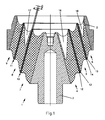
- the layer spring 1 shown in Figures 1 and 2 is in longitudinal section or shown in plan view.
- the layer spring 1 consists in essentially from the outer connection part 2, the inner connection part 3 and the intermediate spring layers 4, 5, and 6.
- Each spring layer 4 to 6 consists of an elastomer insert 7, 8, and 9, with their conical sides with the connecting parts 2 or 3 and / or the sheet inserts 10 or 11 are connected.
- the sheet inserts 10 or 11 consist of two individual sheets 12, 13 and 14, 15 respectively lie flush against each other. To twist the individual sheets to each other To prevent the individual sheets from being connected to each other during operation bonded.
- the dimensions of the layer spring 1 can be chosen that they are identical to the dimensions of a layer spring known per se are.
- the new layer spring can therefore be used instead of the previous layer spring the machine in question or installed in the vehicle.
- the particular advantage of the new layer spring 1 is that the individual parts, that is, the respective elastomer inserts 7 to 9 with their Connecting parts 2 or 3 and the individual sheets 12 to 15 are manufactured separately can be and only then assembled into a layer spring 1 can be.
- the individual production of the spring layers 4 to 6 enables Production of elastomer inserts 7 to 9 with very different Mixtures and thus also very different chemical and physical properties. They can be run hard or soft as required.
- the selection of the individual is also based on this Spring layers 4 to 6, depending on the intended use.
- Through the inventive formation of the layer fields is a twist of the Elastomer inserts possible. As a result, the so-called windows 16, 17 and 18 of the individual layers 7, 8 and 9 rotated into a desired position to achieve the desired travel in the X, Y and Z directions adjust.
- an ultra socket 20 is shown, which after the Principle according to the invention is formed.
- the ultra jack 20 is one Layer spring 21 provided.
- the layer spring 21 has the outer connecting part 22 and the inner connecting part 23. In between are the two spring layers 24 and 25.
- Each spring layer 24 and 25 has an elastomer insert 27 and 28.
- the sheet metal insert is located between the elastomer inserts 27 and 28 29 which consists of the two individual sheets 30 and 31.
- the thickness of the Individual sheets 30 and 31 is d which is half the thickness D of a conventional one Sheet insert corresponds.
- Both in the outer spring layer 24 and in the inner spring layer 25 are windows 32 and 33, respectively accommodated.
- the individual production of the spring layers 24 and 25 enables here, too, the windows 32 and 33 have a very different orientation to each other, as shown for example in Figure 4.
- the windows 32 extend over 90 ° and the windows 33 over 70 ° on the respective Scope of the elastomer insert 27 or 28.
- When installing the individual spring layers 24 and 25 can twisted the same against each other until windows 32 and 33 come to lie in the desired position.
Landscapes
- Engineering & Computer Science (AREA)
- General Engineering & Computer Science (AREA)
- Mechanical Engineering (AREA)
- Architecture (AREA)
- Springs (AREA)
- Vibration Prevention Devices (AREA)
Abstract
Description
- Figur 1
- einen Schnitt durch eine konusförmige Schichtfeder,
- Figur 2
- Draufsicht von Figur 1
- Figur 3
- einen Längsschnitt gemäß der Linie A-A aus der Figur 4 durch eine Ultrabuchse und
- Figur 4
- eine Stirnansicht der Ultrabuchse.
Claims (10)
- Schichtfeder mit einem äußeren und einem inneren Anschlussteil und dazwischen liegenden Federschichten aus wechselweise einer Elastomer-Einlage und einer Blecheinlage, dadurch gekennzeichnet, dass die Blecheinlagen (10, 11, 29) jeweils aus zwei Einzelblechen (12 bis 15, 30, 31) bestehen.
- Schichtfeder nach Anspruch 1, dadurch gekennzeichnet, dass die Einzelbleche (12 bis 15, 30, 31) form- oder kraftschlüssig miteinander verbunden sind.
- Schichtfeder nach einem der Ansprüche 1 oder 2, dadurch gekennzeichnet, dass die Einzelbleche (12 bis 15, 30, 31) miteinander verklebt sind.
- Schichtfeder nach einem der Ansprüche 1 bis 3, dadurch gekennzeichnet, dass die Elastomer-Einlagen (7 bis 9, 27, 28) aus unterschiedlichem Elastomermaterial gebildet sind.
- Schichtfeder nach einem der Ansprüche 1 bis 4, dadurch gekennzeichnet, dass die Elastomer-Einlagen (7 bis 9, 27, 28) eine unterschiedliche Shorehärte haben.
- Schichtfeder nach einem der Ansprüche 1 bis 5, dadurch gekennzeichnet, dass die Einzelbleche (12 bis 15, 30, 31) eine Dicke (d) haben, welche der halben Dicke (D) einer üblichen bekannten Blecheinlage entspricht.
- Verfahren zur Herstellung einer Schichtfeder nach einem der Ansprüche 1 bis 6, dadurch gekennzeichnet, dass die einzelnen Elastomer-Einlagen (7 bis 9, 27, 28) an ihren Stützflächen auf der einen Seite mit einem Anschlussteil (2, 3, 22, 23) und auf der anderen Seite mit einem Einzelblech (12 bis 15, 30, 31) oder auf beiden Seiten mit Einzelblechen (13, 14) verbunden werden.
- Verfahren zur Herstellung einer Schichtfeder nach Anspruch 7, dadurch gekennzeichnet, dass die Verbindung der Elastomer-Einlagen (7 bis 9, 27, 28) mit den Anschlussteilen (2, 3, 22, 23) beziehungsweise Einzelblechen 12 bis 15, 30, 31) durch Vulkanisation erfolgt.
- Verfahren zur Herstellung einer Schichtfeder nach einem der Ansprüche 7 oder 8, dadurch gekennzeichnet, dass die Schichtfeder (1, 21) durch Zusammenfügen einzelner zueinander passender Federschichten (4 bis 6, 24, 25) gebildet wird.
- Verfahren zur Herstellung einer Schichtfeder nach einem der Ansprüche 7 bis 9, dadurch gekennzeichnet, dass bei Einsatz eines gleichen Elastomermaterials die Vulkanisationen in einem üblichen Spritzgießwerkzeug erfolgt.
Applications Claiming Priority (2)
| Application Number | Priority Date | Filing Date | Title |
|---|---|---|---|
| DE10301756 | 2003-01-18 | ||
| DE10301756A DE10301756B4 (de) | 2003-01-18 | 2003-01-18 | Schichtfeder |
Publications (2)
| Publication Number | Publication Date |
|---|---|
| EP1439319A1 true EP1439319A1 (de) | 2004-07-21 |
| EP1439319B1 EP1439319B1 (de) | 2005-12-21 |
Family
ID=32520023
Family Applications (1)
| Application Number | Title | Priority Date | Filing Date |
|---|---|---|---|
| EP03026201A Expired - Lifetime EP1439319B1 (de) | 2003-01-18 | 2003-11-14 | Schichtfeder und Verfahren zu seiner Herstellung |
Country Status (4)
| Country | Link |
|---|---|
| EP (1) | EP1439319B1 (de) |
| AT (1) | ATE313736T1 (de) |
| DE (2) | DE10301756B4 (de) |
| ES (1) | ES2252608T3 (de) |
Cited By (5)
| Publication number | Priority date | Publication date | Assignee | Title |
|---|---|---|---|---|
| JP2009052604A (ja) * | 2007-08-24 | 2009-03-12 | Toyo Tire & Rubber Co Ltd | 車両用懸架装置 |
| JP2018100761A (ja) * | 2016-12-21 | 2018-06-28 | 東洋ゴム工業株式会社 | 軸ばね |
| JP2018100760A (ja) * | 2016-12-21 | 2018-06-28 | 東洋ゴム工業株式会社 | 軸ばね |
| JP2018100759A (ja) * | 2016-12-21 | 2018-06-28 | 東洋ゴム工業株式会社 | 軸ばね |
| CN113631826A (zh) * | 2019-03-22 | 2021-11-09 | Gmt古米金属技术有限公司 | 弹簧元件和阻燃的覆盖层 |
Families Citing this family (5)
| Publication number | Priority date | Publication date | Assignee | Title |
|---|---|---|---|---|
| DE102005012751B4 (de) * | 2005-03-19 | 2012-10-31 | Contitech Vibration Control Gmbh | Gelenklagerbuchse, insbesondere für einen Achslenker eines Kraftfahrzeugs |
| DE102005028565A1 (de) * | 2005-06-21 | 2007-01-04 | Contitech Luftfedersysteme Gmbh | Hochelastische Schichtfeder |
| DE102015104027B4 (de) * | 2015-03-11 | 2016-11-10 | Federnfabrik Dietz Gmbh | Verfahren zur Herstellung eines Federelementes mit einem Dämpfungselement |
| JP6789094B2 (ja) * | 2016-12-21 | 2020-11-25 | Toyo Tire株式会社 | 軸ばね |
| DE102023135919A1 (de) | 2023-12-20 | 2025-06-26 | Mahle International Gmbh | Dämpfungselement für ein Elektrofahrrad und ein Elektrofahrrad |
Citations (5)
| Publication number | Priority date | Publication date | Assignee | Title |
|---|---|---|---|---|
| GB259848A (en) * | 1926-01-13 | 1926-10-21 | Ringfeder Gmbh | Improved annular spring |
| US2641463A (en) * | 1950-04-01 | 1953-06-09 | Miner Inc W H | Friction snubber for railway car truck springs |
| US2655005A (en) * | 1952-10-21 | 1953-10-13 | Raymond Concrete Pile Co | Wharf fender |
| GB737912A (en) * | 1951-04-13 | 1955-10-05 | Alexander Eric Moulton | Improvements in and relating to the manufacture of rubber springs |
| US3679197A (en) * | 1971-05-27 | 1972-07-25 | Lord Corp | Compressive load carrying bearings |
Family Cites Families (2)
| Publication number | Priority date | Publication date | Assignee | Title |
|---|---|---|---|---|
| FR2652865A1 (fr) * | 1989-10-05 | 1991-04-12 | Caoutchouc Manuf Plastique | Procede de realisation de pieces elastiques a rigidites differenciees dans les trois directions par emmanchement de pieces cylindriques a armatures rigides. |
| JPH09317806A (ja) * | 1996-05-24 | 1997-12-12 | Toyo Tire & Rubber Co Ltd | 筒型防振ゴム |
-
2003
- 2003-01-18 DE DE10301756A patent/DE10301756B4/de not_active Expired - Fee Related
- 2003-11-14 DE DE50301984T patent/DE50301984D1/de not_active Expired - Lifetime
- 2003-11-14 AT AT03026201T patent/ATE313736T1/de not_active IP Right Cessation
- 2003-11-14 ES ES03026201T patent/ES2252608T3/es not_active Expired - Lifetime
- 2003-11-14 EP EP03026201A patent/EP1439319B1/de not_active Expired - Lifetime
Patent Citations (5)
| Publication number | Priority date | Publication date | Assignee | Title |
|---|---|---|---|---|
| GB259848A (en) * | 1926-01-13 | 1926-10-21 | Ringfeder Gmbh | Improved annular spring |
| US2641463A (en) * | 1950-04-01 | 1953-06-09 | Miner Inc W H | Friction snubber for railway car truck springs |
| GB737912A (en) * | 1951-04-13 | 1955-10-05 | Alexander Eric Moulton | Improvements in and relating to the manufacture of rubber springs |
| US2655005A (en) * | 1952-10-21 | 1953-10-13 | Raymond Concrete Pile Co | Wharf fender |
| US3679197A (en) * | 1971-05-27 | 1972-07-25 | Lord Corp | Compressive load carrying bearings |
Cited By (6)
| Publication number | Priority date | Publication date | Assignee | Title |
|---|---|---|---|---|
| JP2009052604A (ja) * | 2007-08-24 | 2009-03-12 | Toyo Tire & Rubber Co Ltd | 車両用懸架装置 |
| JP2018100761A (ja) * | 2016-12-21 | 2018-06-28 | 東洋ゴム工業株式会社 | 軸ばね |
| JP2018100760A (ja) * | 2016-12-21 | 2018-06-28 | 東洋ゴム工業株式会社 | 軸ばね |
| JP2018100759A (ja) * | 2016-12-21 | 2018-06-28 | 東洋ゴム工業株式会社 | 軸ばね |
| CN113631826A (zh) * | 2019-03-22 | 2021-11-09 | Gmt古米金属技术有限公司 | 弹簧元件和阻燃的覆盖层 |
| CN113631826B (zh) * | 2019-03-22 | 2024-04-19 | Gmt古米金属技术有限公司 | 弹簧元件和阻燃的覆盖层 |
Also Published As
| Publication number | Publication date |
|---|---|
| ATE313736T1 (de) | 2006-01-15 |
| DE10301756A1 (de) | 2004-07-29 |
| ES2252608T3 (es) | 2006-05-16 |
| EP1439319B1 (de) | 2005-12-21 |
| DE10301756B4 (de) | 2005-02-24 |
| DE50301984D1 (de) | 2006-01-26 |
Similar Documents
| Publication | Publication Date | Title |
|---|---|---|
| DE60121891T2 (de) | Drehgelenk, zum Beispiel für einen Stabilisator eines Radfahrzeuges | |
| DE3038356A1 (de) | Elastisches zylindrisches lager | |
| DD292689A5 (de) | Gummifederelement | |
| DE102016215938B4 (de) | Verfahren zur Herstellung einer Blattfeder, sowie Blattfeder und Fahrwerk für ein Kraftfahrzeug | |
| DE102011121831A1 (de) | Elastisches Gelenk insbesondere für eine Radaufhängung eines Kraftfahrzeugs | |
| WO2010017875A1 (de) | Steuerkolben für schieberventile und verfahren zu seiner herstellung | |
| EP1439319B1 (de) | Schichtfeder und Verfahren zu seiner Herstellung | |
| DE2819306C2 (de) | ||
| DE102004010768B4 (de) | Blattfeder für eine Radaufhängung an einem Fahrzeug | |
| EP2422906B1 (de) | Werkzeughalter mit Ausweichmechanismus sowie Verfahren zu dessen Herstellung | |
| EP1165984A1 (de) | Gummilager | |
| DE102017127404B4 (de) | Kugelgewindetrieb | |
| DE102011052747A1 (de) | Spannelement für eine Spannvorrichtung | |
| DE202011051001U1 (de) | Spannelement für eine Spannvorrichtung | |
| EP2856913A1 (de) | Plattenartiges Möbelteil | |
| EP1762747A1 (de) | Buchse | |
| DE3741731A1 (de) | Stossdaempferfeder | |
| DE2109916C2 (de) | Verfahren zur Herstellung eines Scharnieres und in diesem Verfahren hergestelltes Scharnier | |
| DE102011052741A1 (de) | Spannelement für eine Spannvorrichtung | |
| EP1782975B1 (de) | Führungselement für ein Führungsbahn-Element in einer Radaufhängung eines Fahrzeugs | |
| DE202011050998U1 (de) | Spannelement für eine Spannvorrichtung | |
| DE102018000644A1 (de) | Verfahren zum Verschließen einer Öffnung mit einem Verschlussmittel | |
| DE102014221111A1 (de) | Spritzgußteil, insbesondere Drosselscheibe eines Hydrolagers bzw. einer Hydrobuchse | |
| DE2712185A1 (de) | Federvorrichtung | |
| WO2015132413A1 (de) | Verriegelungssystem mit kontaktflächen |
Legal Events
| Date | Code | Title | Description |
|---|---|---|---|
| PUAI | Public reference made under article 153(3) epc to a published international application that has entered the european phase |
Free format text: ORIGINAL CODE: 0009012 |
|
| 17P | Request for examination filed |
Effective date: 20040506 |
|
| AK | Designated contracting states |
Kind code of ref document: A1 Designated state(s): AT BE BG CH CY CZ DE DK EE ES FI FR GB GR HU IE IT LI LU MC NL PT RO SE SI SK TR |
|
| AX | Request for extension of the european patent |
Extension state: AL LT LV MK |
|
| 17Q | First examination report despatched |
Effective date: 20040830 |
|
| AKX | Designation fees paid |
Designated state(s): AT BE BG CH CY CZ DE DK EE ES FI FR GB GR HU IE IT LI LU MC NL PT RO SE SI SK TR |
|
| GRAP | Despatch of communication of intention to grant a patent |
Free format text: ORIGINAL CODE: EPIDOSNIGR1 |
|
| GRAS | Grant fee paid |
Free format text: ORIGINAL CODE: EPIDOSNIGR3 |
|
| GRAA | (expected) grant |
Free format text: ORIGINAL CODE: 0009210 |
|
| AK | Designated contracting states |
Kind code of ref document: B1 Designated state(s): AT BE BG CH CY CZ DE DK EE ES FI FR GB GR HU IE IT LI LU MC NL PT RO SE SI SK TR |
|
| PG25 | Lapsed in a contracting state [announced via postgrant information from national office to epo] |
Ref country code: CZ Free format text: LAPSE BECAUSE OF FAILURE TO SUBMIT A TRANSLATION OF THE DESCRIPTION OR TO PAY THE FEE WITHIN THE PRESCRIBED TIME-LIMIT Effective date: 20051221 Ref country code: IT Free format text: LAPSE BECAUSE OF FAILURE TO SUBMIT A TRANSLATION OF THE DESCRIPTION OR TO PAY THE FEE WITHIN THE PRESCRIBED TIME-LIMIT;WARNING: LAPSES OF ITALIAN PATENTS WITH EFFECTIVE DATE BEFORE 2007 MAY HAVE OCCURRED AT ANY TIME BEFORE 2007. THE CORRECT EFFECTIVE DATE MAY BE DIFFERENT FROM THE ONE RECORDED. Effective date: 20051221 Ref country code: IE Free format text: LAPSE BECAUSE OF FAILURE TO SUBMIT A TRANSLATION OF THE DESCRIPTION OR TO PAY THE FEE WITHIN THE PRESCRIBED TIME-LIMIT Effective date: 20051221 Ref country code: SI Free format text: LAPSE BECAUSE OF FAILURE TO SUBMIT A TRANSLATION OF THE DESCRIPTION OR TO PAY THE FEE WITHIN THE PRESCRIBED TIME-LIMIT Effective date: 20051221 Ref country code: RO Free format text: LAPSE BECAUSE OF FAILURE TO SUBMIT A TRANSLATION OF THE DESCRIPTION OR TO PAY THE FEE WITHIN THE PRESCRIBED TIME-LIMIT Effective date: 20051221 Ref country code: SK Free format text: LAPSE BECAUSE OF FAILURE TO SUBMIT A TRANSLATION OF THE DESCRIPTION OR TO PAY THE FEE WITHIN THE PRESCRIBED TIME-LIMIT Effective date: 20051221 Ref country code: NL Free format text: LAPSE BECAUSE OF FAILURE TO SUBMIT A TRANSLATION OF THE DESCRIPTION OR TO PAY THE FEE WITHIN THE PRESCRIBED TIME-LIMIT Effective date: 20051221 Ref country code: FI Free format text: LAPSE BECAUSE OF FAILURE TO SUBMIT A TRANSLATION OF THE DESCRIPTION OR TO PAY THE FEE WITHIN THE PRESCRIBED TIME-LIMIT Effective date: 20051221 |
|
| REG | Reference to a national code |
Ref country code: GB Ref legal event code: FG4D Free format text: NOT ENGLISH |
|
| REG | Reference to a national code |
Ref country code: CH Ref legal event code: EP |
|
| REG | Reference to a national code |
Ref country code: IE Ref legal event code: FG4D Free format text: LANGUAGE OF EP DOCUMENT: GERMAN |
|
| REF | Corresponds to: |
Ref document number: 50301984 Country of ref document: DE Date of ref document: 20060126 Kind code of ref document: P |
|
| PG25 | Lapsed in a contracting state [announced via postgrant information from national office to epo] |
Ref country code: BG Free format text: LAPSE BECAUSE OF FAILURE TO SUBMIT A TRANSLATION OF THE DESCRIPTION OR TO PAY THE FEE WITHIN THE PRESCRIBED TIME-LIMIT Effective date: 20060321 Ref country code: DK Free format text: LAPSE BECAUSE OF FAILURE TO SUBMIT A TRANSLATION OF THE DESCRIPTION OR TO PAY THE FEE WITHIN THE PRESCRIBED TIME-LIMIT Effective date: 20060321 Ref country code: SE Free format text: LAPSE BECAUSE OF FAILURE TO SUBMIT A TRANSLATION OF THE DESCRIPTION OR TO PAY THE FEE WITHIN THE PRESCRIBED TIME-LIMIT Effective date: 20060321 Ref country code: GR Free format text: LAPSE BECAUSE OF FAILURE TO SUBMIT A TRANSLATION OF THE DESCRIPTION OR TO PAY THE FEE WITHIN THE PRESCRIBED TIME-LIMIT Effective date: 20060321 |
|
| GBT | Gb: translation of ep patent filed (gb section 77(6)(a)/1977) |
Effective date: 20060224 |
|
| REG | Reference to a national code |
Ref country code: ES Ref legal event code: FG2A Ref document number: 2252608 Country of ref document: ES Kind code of ref document: T3 |
|
| PG25 | Lapsed in a contracting state [announced via postgrant information from national office to epo] |
Ref country code: PT Free format text: LAPSE BECAUSE OF FAILURE TO SUBMIT A TRANSLATION OF THE DESCRIPTION OR TO PAY THE FEE WITHIN THE PRESCRIBED TIME-LIMIT Effective date: 20060522 |
|
| NLV1 | Nl: lapsed or annulled due to failure to fulfill the requirements of art. 29p and 29m of the patents act | ||
| PG25 | Lapsed in a contracting state [announced via postgrant information from national office to epo] |
Ref country code: HU Free format text: LAPSE BECAUSE OF FAILURE TO SUBMIT A TRANSLATION OF THE DESCRIPTION OR TO PAY THE FEE WITHIN THE PRESCRIBED TIME-LIMIT Effective date: 20060622 |
|
| ET | Fr: translation filed | ||
| REG | Reference to a national code |
Ref country code: IE Ref legal event code: FD4D |
|
| PLBE | No opposition filed within time limit |
Free format text: ORIGINAL CODE: 0009261 |
|
| STAA | Information on the status of an ep patent application or granted ep patent |
Free format text: STATUS: NO OPPOSITION FILED WITHIN TIME LIMIT |
|
| 26N | No opposition filed |
Effective date: 20060922 |
|
| PG25 | Lapsed in a contracting state [announced via postgrant information from national office to epo] |
Ref country code: MC Free format text: LAPSE BECAUSE OF NON-PAYMENT OF DUE FEES Effective date: 20061130 Ref country code: BE Free format text: LAPSE BECAUSE OF NON-PAYMENT OF DUE FEES Effective date: 20061130 |
|
| BERE | Be: lapsed |
Owner name: CARL FREUDENBERG K.G. Effective date: 20061130 |
|
| PG25 | Lapsed in a contracting state [announced via postgrant information from national office to epo] |
Ref country code: AT Free format text: LAPSE BECAUSE OF NON-PAYMENT OF DUE FEES Effective date: 20061114 |
|
| PG25 | Lapsed in a contracting state [announced via postgrant information from national office to epo] |
Ref country code: EE Free format text: LAPSE BECAUSE OF FAILURE TO SUBMIT A TRANSLATION OF THE DESCRIPTION OR TO PAY THE FEE WITHIN THE PRESCRIBED TIME-LIMIT Effective date: 20051221 |
|
| PG25 | Lapsed in a contracting state [announced via postgrant information from national office to epo] |
Ref country code: LI Free format text: LAPSE BECAUSE OF NON-PAYMENT OF DUE FEES Effective date: 20071130 Ref country code: CH Free format text: LAPSE BECAUSE OF NON-PAYMENT OF DUE FEES Effective date: 20071130 Ref country code: TR Free format text: LAPSE BECAUSE OF FAILURE TO SUBMIT A TRANSLATION OF THE DESCRIPTION OR TO PAY THE FEE WITHIN THE PRESCRIBED TIME-LIMIT Effective date: 20051221 Ref country code: LU Free format text: LAPSE BECAUSE OF NON-PAYMENT OF DUE FEES Effective date: 20061114 |
|
| REG | Reference to a national code |
Ref country code: CH Ref legal event code: PL |
|
| PG25 | Lapsed in a contracting state [announced via postgrant information from national office to epo] |
Ref country code: CY Free format text: LAPSE BECAUSE OF FAILURE TO SUBMIT A TRANSLATION OF THE DESCRIPTION OR TO PAY THE FEE WITHIN THE PRESCRIBED TIME-LIMIT Effective date: 20051221 |
|
| REG | Reference to a national code |
Ref country code: FR Ref legal event code: PLFP Year of fee payment: 13 |
|
| REG | Reference to a national code |
Ref country code: FR Ref legal event code: PLFP Year of fee payment: 14 |
|
| REG | Reference to a national code |
Ref country code: FR Ref legal event code: PLFP Year of fee payment: 15 |
|
| PGFP | Annual fee paid to national office [announced via postgrant information from national office to epo] |
Ref country code: DE Payment date: 20191128 Year of fee payment: 17 |
|
| PGFP | Annual fee paid to national office [announced via postgrant information from national office to epo] |
Ref country code: ES Payment date: 20191211 Year of fee payment: 17 Ref country code: FR Payment date: 20191124 Year of fee payment: 17 Ref country code: IT Payment date: 20191129 Year of fee payment: 17 |
|
| PGFP | Annual fee paid to national office [announced via postgrant information from national office to epo] |
Ref country code: GB Payment date: 20191122 Year of fee payment: 17 |
|
| REG | Reference to a national code |
Ref country code: DE Ref legal event code: R119 Ref document number: 50301984 Country of ref document: DE |
|
| GBPC | Gb: european patent ceased through non-payment of renewal fee |
Effective date: 20201114 |
|
| PG25 | Lapsed in a contracting state [announced via postgrant information from national office to epo] |
Ref country code: FR Free format text: LAPSE BECAUSE OF NON-PAYMENT OF DUE FEES Effective date: 20201130 Ref country code: IT Free format text: LAPSE BECAUSE OF NON-PAYMENT OF DUE FEES Effective date: 20201114 |
|
| PG25 | Lapsed in a contracting state [announced via postgrant information from national office to epo] |
Ref country code: DE Free format text: LAPSE BECAUSE OF NON-PAYMENT OF DUE FEES Effective date: 20210601 Ref country code: GB Free format text: LAPSE BECAUSE OF NON-PAYMENT OF DUE FEES Effective date: 20201114 |
|
| REG | Reference to a national code |
Ref country code: ES Ref legal event code: FD2A Effective date: 20220201 |
|
| PG25 | Lapsed in a contracting state [announced via postgrant information from national office to epo] |
Ref country code: ES Free format text: LAPSE BECAUSE OF NON-PAYMENT OF DUE FEES Effective date: 20201115 |