EP1439311A1 - Linearantrieb mit Positionserfassungsmitteln - Google Patents
Linearantrieb mit Positionserfassungsmitteln Download PDFInfo
- Publication number
- EP1439311A1 EP1439311A1 EP03027188A EP03027188A EP1439311A1 EP 1439311 A1 EP1439311 A1 EP 1439311A1 EP 03027188 A EP03027188 A EP 03027188A EP 03027188 A EP03027188 A EP 03027188A EP 1439311 A1 EP1439311 A1 EP 1439311A1
- Authority
- EP
- European Patent Office
- Prior art keywords
- linear drive
- guide
- linear
- drive according
- housing
- Prior art date
- Legal status (The legal status is an assumption and is not a legal conclusion. Google has not performed a legal analysis and makes no representation as to the accuracy of the status listed.)
- Granted
Links
- 230000033001 locomotion Effects 0.000 claims abstract description 15
- 230000005291 magnetic effect Effects 0.000 claims description 19
- 238000001514 detection method Methods 0.000 claims description 16
- 239000000463 material Substances 0.000 claims description 14
- 238000011156 evaluation Methods 0.000 claims description 5
- 239000004020 conductor Substances 0.000 claims description 4
- 230000000295 complement effect Effects 0.000 claims description 3
- XAGFODPZIPBFFR-UHFFFAOYSA-N aluminium Chemical group [Al] XAGFODPZIPBFFR-UHFFFAOYSA-N 0.000 claims description 2
- 229910052782 aluminium Inorganic materials 0.000 claims description 2
- 239000003302 ferromagnetic material Substances 0.000 claims description 2
- 238000005259 measurement Methods 0.000 abstract description 3
- 238000013461 design Methods 0.000 description 6
- 238000004519 manufacturing process Methods 0.000 description 5
- 230000008878 coupling Effects 0.000 description 4
- 238000010168 coupling process Methods 0.000 description 4
- 238000005859 coupling reaction Methods 0.000 description 4
- 238000011161 development Methods 0.000 description 4
- 230000018109 developmental process Effects 0.000 description 4
- 239000012530 fluid Substances 0.000 description 4
- 238000001125 extrusion Methods 0.000 description 3
- 230000010354 integration Effects 0.000 description 3
- 238000011109 contamination Methods 0.000 description 2
- 238000000034 method Methods 0.000 description 2
- 238000005096 rolling process Methods 0.000 description 2
- 238000007789 sealing Methods 0.000 description 2
- 229910000760 Hardened steel Inorganic materials 0.000 description 1
- 238000012356 Product development Methods 0.000 description 1
- 238000004026 adhesive bonding Methods 0.000 description 1
- 230000005540 biological transmission Effects 0.000 description 1
- 239000003795 chemical substances by application Substances 0.000 description 1
- 238000010276 construction Methods 0.000 description 1
- 230000001419 dependent effect Effects 0.000 description 1
- 230000001627 detrimental effect Effects 0.000 description 1
- 238000005516 engineering process Methods 0.000 description 1
- 230000007613 environmental effect Effects 0.000 description 1
- 238000009434 installation Methods 0.000 description 1
- 238000012423 maintenance Methods 0.000 description 1
- 230000000873 masking effect Effects 0.000 description 1
- 230000003287 optical effect Effects 0.000 description 1
- 230000035515 penetration Effects 0.000 description 1
- 239000006187 pill Substances 0.000 description 1
- 238000012797 qualification Methods 0.000 description 1
- 230000001360 synchronised effect Effects 0.000 description 1
- 238000010626 work up procedure Methods 0.000 description 1
Images

Classifications
-
- F—MECHANICAL ENGINEERING; LIGHTING; HEATING; WEAPONS; BLASTING
- F15—FLUID-PRESSURE ACTUATORS; HYDRAULICS OR PNEUMATICS IN GENERAL
- F15B—SYSTEMS ACTING BY MEANS OF FLUIDS IN GENERAL; FLUID-PRESSURE ACTUATORS, e.g. SERVOMOTORS; DETAILS OF FLUID-PRESSURE SYSTEMS, NOT OTHERWISE PROVIDED FOR
- F15B15/00—Fluid-actuated devices for displacing a member from one position to another; Gearing associated therewith
- F15B15/20—Other details, e.g. assembly with regulating devices
- F15B15/28—Means for indicating the position, e.g. end of stroke
- F15B15/2892—Means for indicating the position, e.g. end of stroke characterised by the attachment means
-
- F—MECHANICAL ENGINEERING; LIGHTING; HEATING; WEAPONS; BLASTING
- F15—FLUID-PRESSURE ACTUATORS; HYDRAULICS OR PNEUMATICS IN GENERAL
- F15B—SYSTEMS ACTING BY MEANS OF FLUIDS IN GENERAL; FLUID-PRESSURE ACTUATORS, e.g. SERVOMOTORS; DETAILS OF FLUID-PRESSURE SYSTEMS, NOT OTHERWISE PROVIDED FOR
- F15B15/00—Fluid-actuated devices for displacing a member from one position to another; Gearing associated therewith
- F15B15/20—Other details, e.g. assembly with regulating devices
- F15B15/28—Means for indicating the position, e.g. end of stroke
- F15B15/2815—Position sensing, i.e. means for continuous measurement of position, e.g. LVDT
- F15B15/2861—Position sensing, i.e. means for continuous measurement of position, e.g. LVDT using magnetic means
Definitions
- the invention relates to a linear drive, with a drive housing, in which at least one to a drive movement drivable drive part is arranged with a Guide carriage is motion-coupled to the fastener intended to attach a load to be moved and one on at least one guide rail
- Linear guide arranged on the outside of the drive housing in this way is linearly displaceable that the to be moved by the Load on it lateral forces from the linear guide be recorded, and with position detection means for the guide carriage, the one in a housing extending along the travel path of the guide carriage, electronically evaluable measuring section unit and one with the Guide carriage motion-coupled permanent magnetic Actuating unit for actuating the measuring section unit having.
- the position detection means a separate housing, This is done using fastening tabs on the actuator housing of the linear actuator is fixed.
- this separate housing is one Measuring section unit working on the magnetostrictive principle housed by a permanent magnetic actuator is excited, which is adjustable in a on the housing arranged runners sits. The runner is over one Coupling link with the guide slide of the linear drive coupled to a linear guide on the outside of the drive housing is stored. A load to be moved is on the guide carriage attached, the linear guide being the one of the load exerted transverse forces so that the runner of the position detection means is not charged.
- EP 0649004 B1 has already proposed that one formed by a conventional cylinder Linear drive the measuring section unit of the position detection means to accommodate in the drive housing and the actuation unit to integrate into the drive part. At this Configuration, however, no guide carriage is provided, so that the use is limited to use cases, where there are no large transverse forces. Also requires the integration of the actuation unit in the drive part a relatively large manufacturing effort.
- the linear guide can have a single guide rail, that gripped like a rider by the guide carriage becomes.
- One with the drive housing is particularly easy to manufacture one-piece design of the guide rail.
- the drive housing including the molded guide rail getting produced.
- the Recording channel can be formed in a precise parallel position.
- An attachment can then, for example, by gluing, by rolling in or screwing on.
- the linear drive can be a fluid force actuated linear drive or an electrically operated Act linear actuator. There are designs with and without Piston rod possible.
- Position detection devices have proven to be particularly precise proven that are based on the magnetostrictive principle.
- the actuating unit of the position detection means is preferred well protected inside the guide carriage. It can also be very close to the Guide rail and thus placed at the measuring section unit become.
- a particularly simple assembly for the measuring section unit results when the receiving channel is one to the outer contour of the Measuring section unit has complementary inner contour, wherein it is expedient to have a circular contour.
- the measuring section unit can be viewed from one end be inserted into the receiving channel of the guide rail.
- the concept according to the invention can be used for different Use types of linear drives. You can interpret it like this that the development costs and the effort for trials and Qualifications do not arise with every product development, universal use is possible. The development times and the development costs can therefore be reduced become. Due to the multifunctionality of the guide rail, on the one hand as a linear guide for the guide carriage and on the other hand as a receptacle for the measuring section unit, space can be saved, which allows compact dimensions.
- the embodiment is one in his Set of fluid-actuated linear drives provided with reference number 1, especially with compressed air as the driving fluid is operated.
- a hydraulic mode of operation would be, however also conceivable.
- the linear drive 1 shown belongs to the genus of rodless Linear drives. However, the invention could also realized in connection with a linear drive be that has at least one piston rod. Furthermore it should be mentioned that the measures according to the invention also suitable for electrically actuated linear drives.
- the linear drive 1 has an elongated, tubular Drive housing 2, the one from one end to the other in Longitudinal continuous interior 3 defined and at the two end faces each closing the interior 3 Housing cover 4, 5 is attached.
- each work space 12 communicates with its own control opening 13a, 13b, via which the working fluid is supplied and removed can be to drive part 7 to a linear movement in one direction or another.
- the linear movement of the drive part 7 is, at least in Direction of the longitudinal axis 6 without play, on one outside of the drive housing 2 arranged guide carriage 14 transmitted.
- This is equipped with fasteners 15 - for example Mounting grooves and / or mounting holes -, which a particularly releasable attachment of a to be transported Allow load 16.
- the load 16 can, for example be formed by a gripping device when the linear drive is used in handling technology.
- the too transporting load 16 is only dash-dotted in the drawing indicated.
- the axially backlash-free motion coupling between the drive part 7 and the guide carriage 14 by a Carrier 17 realizes a longitudinal slot 18 of the drive housing 2 and the interior 3 with the Drive part 7 and outside of the drive housing 2 with the Guide carriage 14 is connected.
- the longitudinal slot 18 is located at one point on the circumference of the interior 3, being radially inside in the interior 3 and radially outside Outer surface of the drive housing 2 opens out.
- a flexible sealing tape 22 which is axially on both sides the drive part 7 with a seal on the two Flanks of the longitudinal slot 18 is present. That way no working fluid can escape from the working spaces 12.
- the sealing tape to the interior 3 lifted off from the longitudinal slot 18, so that the preferred web-like driver 17 through the longitudinal slot 18th can reach through.
- a flexible masking tape 21 may be associated with penetration prevented from contamination in the longitudinal slot 18.
- rodless linear drive 1 of the embodiment it is a so-called slot cylinder.
- the linear drive 1 could be used to couple the movement of the drive part 7 and guide carriage 14 also via a piston rod feature.
- the piston rod would then be on the drive part 7 attack and at least one of the housing covers 4, 5 after enforce outside, being outside the drive housing 2, by a suitable mechanical connection device, drivingly connected to the guide carriage 14 is.
- the linear drive could also have several drive parts 7, that together on one and the same guide carriage 14 act.
- An electric linear drive could be used as a drive part 7 a rotatably fixed nut can be provided, which on a extending between the two housing covers 4, 5 Spindle is arranged by an electric motor can be rotated to a linear movement of the Mother and the guide carriage coupled to this movement 14 cause.
- This linear guide 23 contains at least one - in the exemplary embodiment exactly one - guide rail 24, which is arranged on the outer circumference of the drive housing 2 is and over its entire length, parallel to Longitudinal axis 6 extends. It is fixed to the drive housing 2 connected.
- the guide rail 24 is preferred by the guide carriage 14 encompassed like a rider, as exemplified in FIG evident.
- the guide rail 24 has against each other opposite long sides across parallel, towards the Longitudinal axis 6 extending guideways 25 with which on the guide carriage 14 fixed guide elements 26 in guide engagement stand. It can be an educational design a sliding guide or to form a rolling guide act.
- the guide rail 24 is in one piece formed with the drive housing 2.
- the one-piece is expediently only on a rib-like protruding from the drive housing 2, over the entire length of the drive housing 2 continuous base body 27, which is made of the same material as the drive housing 2 exists. It is convenient aluminum material or another non-ferromagnetic material Material for reasons to be explained is able to pass a magnetic field.
- the drive housing together with the base body 27 be produced by extrusion.
- the guideways 25 on separate guide rails 28 provide with which the base body 27 is equipped.
- These can then be made from a wear-resistant material the selection of which is independent of the choice of material of the base body 27. For example, they consist of hardened Steel.
- the linear drive 1 is equipped with position detection means, all of which are provided with reference number 32 are. With them it is possible to take any momentary axial position of the guide carriage 14 with respect to the drive housing 2 to determine. This is a precise control of the linear drive 1 possible and the linear drive 1 in an electronic control system can be integrated. It is then possible, the actuation of the drive part 7 depending on the position to control and also any other position-dependent To initiate functions, for example the actuation of a another linear drive or a load 16 forming Gripping device.
- the position detection means 32 contain an elongated, preferably rod-shaped measuring section unit 33 which sheltered in a housing along the Travel path of the guide carriage 14 extends.
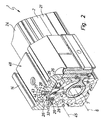
- This housing is formed directly by the guide rail 24, which penetrate the base body 27 in the longitudinal direction Receiving channel 34 into which the measuring section unit 33 is inserted from one end.
- the receiving channel 34 expediently extends over the entire Length of the guide rail 24 through and opens to both End faces. Will the guide rail 24 during manufacture of the drive housing 2 with molded, is in the corresponding Extrusion process advantageously also at the same time the receiving channel 34 is formed. This way you reach an exact parallelism between the longitudinal axis 45 of the receiving channel 34 and that of the guide rail 24.
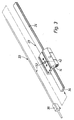
- the receiving channel 34 can also pass through other common manufacturing methods in the guide rail 24 be introduced. This is particularly the case if the guide rail 24 one with respect to the drive housing 2 is a separate component, as shown in Figure 2 by a dash-dotted dividing line is indicated at 35 and how this is also expressed in Figure 3. Then it can act in the receiving channel 34, for example, a bore.
- the Measuring section unit 33 preferably a complementary, circular cylindrical Has outer contour. In this way it is achieved that the inserted measuring section unit 33 without other cross support measures very precisely in the receiving channel 34 is held.
- the measuring section unit 33 Is located at an end region of the measuring section unit 33 a fastening body 36. It can in the inserted state the measuring section unit 33 on the drive housing 2 and / or on assigned housing cover 4 are releasably attached. On in this way, the measuring section unit 33 is fixed to the housing.
- an electronic evaluation unit 37 is arranged via a cable 38 or by other connection measures can be coupled to an external control device. She can if necessary, be integrated into the fastening body 36 and delivers the desired position signals. However, it is quite possible, the evaluation unit not directly on the To provide measuring section unit 33, but to place it externally.
- the receiving channel 34 is closed all around on the circumference. In this way, the measuring section unit 33 is protected from environmental influences well protected.
- the measuring section unit 33 is of a permanent magnetic type Actuating unit 42 actuates itself immediately Board of the carriage 14 is located. The actuation unit 42 thus makes the linear movement of the guide carriage 14 with.
- the actuating unit 42 continuously outputs a magnetic field, which is capable of being at least partially made of magnetic field permeable Material existing guide rail 24 through to get to the measuring section unit 33.
- a magnetic field which is capable of being at least partially made of magnetic field permeable Material existing guide rail 24 through to get to the measuring section unit 33.
- the field lines of permanent magnetic Actuating unit 42 made of material permeable to magnetic fields penetrate existing base body 27 and with large Act field strength on the measuring section unit 33.
- the operating unit 42 can be made compact here like a pill. Prefers it sits in one from the outside in the guide carriage 14 introduced blind hole-like receptacle 43, wherein this receptacle 43 by a press-in cover 44 or can be closed by other measures, so that the actuating unit 42 is held captive.
- the arrangement is preferably such that the longitudinal axis 6 of the interior 3, the longitudinal axis 45 of the receiving channel 34 and the actuating unit 42 lie in a common plane.
- the actuation unit 42 is preferably on the interior 3 radially opposite side of the receiving channel 34 on Guide carriage 14 arranged.
- the recording 43 can in a wing 48 of the guide carriage 14 is formed on which the load 16 to be transported is placed and expediently also with the fastening means 15 Is provided.
- the position detection means 32 preferably work up magnetostrictive principle.
- the Measuring section unit 33 in the exemplary embodiment itself linearly extending sound waveguide 46, which consists of a for Suitable material magnetostriction. He is with the electronic evaluation unit 37 coupled or connectable.
- the electronic evaluation unit 37 coupled or connectable.
- it is tubular, wherein its outer contour corresponds to the inner contour of the receiving channel 34. Extends parallel to this sound waveguide 46 a simple wire, for example electrical conductor 47, which is concentric in the exemplary embodiment arranged in the tubular acoustic waveguide 46 is.
- the electrical Conductor 47 energized with pulses.
- One by the electrical Conductor 47 passed short surge creates one wandering magnetic field, which is where the actuator 42 is currently located locally from the magnetic field of this Actuating unit 42 is superimposed.
- a mechanical tension on the sound waveguide 46 triggers a torsion wave, which moves at the speed of sound continues and at the end of the sound waveguide 46 is converted into electrical impulses.
- the time between the occurrence of these electrical impulses and the initial Current pulse enables the determination in the evaluation unit 37 the current position of the actuator 42 and thus of the guide carriage 14 carrying this.
Landscapes
- Engineering & Computer Science (AREA)
- Physics & Mathematics (AREA)
- Fluid Mechanics (AREA)
- Mechanical Engineering (AREA)
- General Engineering & Computer Science (AREA)
- Linear Motors (AREA)
- Bearings For Parts Moving Linearly (AREA)
- Vehicle Body Suspensions (AREA)
- Character Spaces And Line Spaces In Printers (AREA)
- Moving Of Heads (AREA)
Abstract
Description
- Fig. 1
- eine bevorzugte Ausführungsform des erfindungsgemäßen Linearantriebes in einer perspektivischen Darstellung, teilweise aufgebrochen,
- Fig. 2
- eine perspektivische Querschnittsdarstellung des Linearantriebes aus Fig. 1 gemäß Schnittlinie II-II und
- Fig. 3
- in einer explodierten Einzeldarstellung die bei dem Linearantrieb der Fig. 1 und 2 vorgesehene Linearführung mit zugehörigem Führungsschlitten und der Messstreckeneinheit.
Claims (18)
- Linearantrieb, mit einem Antriebsgehäuse (2), in dem mindestens ein zu einer Antriebsbewegung antreibbares Antriebsteil (7) angeordnet ist, das mit einem Führungsschlitten (14) bewegungsgekoppelt ist, an dem Befestigungsmittel (15) zum Befestigen einer zu bewegenden Last vorgesehen sind und der an mindestens einer Führungsschiene (24) einer außen am Antriebsgehäuse (2) angeordneten Linearführung (23) derart linear verschiebbar geführt ist, dass die durch die zu bewegende Last (16) auf ihn einwirkenden Querkräfte von der Linearführung (23) aufgenommen werden, und mit Positionserfassungsmitteln (32) für den Führungsschlitten (14), die eine sich in einem Gehäuse längs des Verfahrweges des Führungsschlittens (14) erstreckende, elektronisch auswertbare Messstreckeneinheit (33) und eine mit dem Führungsschlitten (14) bewegungsgekoppelte permanentmagnetische Betätigungseinheit (42) zur Betätigung der Messstreckeneinheit (33) aufweisen, dadurch gekennzeichnet, dass die Messstreckeneinheit (33) in einem in einer Führungsschiene (24) der Linearführung (23) ausgebildeten, umfangsseitig geschlossenen Aufnahmekanal (34) sitzt, sodass diese Führungsschiene (24) unmittelbar das Gehäuse für die Messstreckeneinheit (33) bildet, und dass sich die Betätigungseinheit (42) unmittelbar an Bord des Führungsschlittens (14) befindet.
- Linearantrieb nach Anspruch 1, dadurch gekennzeichnet, dass die Linearführung (23) eine einzige Führungsschiene (24) aufweist, die von dem Führungsschlitten (14) reiterartig umgriffen wird.
- Linearantrieb nach Anspruch 1 oder 2, dadurch gekennzeichnet, dass die das Gehäuse für die Messstreckeneinheit (33) bildende Führungsschiene (24) einstückig mit dem Antriebsgehäuse (2) verbunden ist.
- Linearantrieb nach Anspruch 1 oder 2, dadurch gekennzeichnet, dass die das Gehäuse für die Messstreckeneinheit (33) bildende Führungsschiene (24) ein bezüglich des Antriebsgehäuses (2) gesondertes Bauteil ist.
- Linearantrieb nach einem der Ansprüche 1 bis 4, dadurch gekennzeichnet, dass die Führungsschiene (24) zumindest partiell aus magnetfelddurchlässigem Material besteht, um dem Magnetfeld der permanentmagnetischen Betätigungseinheit (42) in jeder Position des Führungsschlittens (14) einen Zugang zur Messstreckeneinheit (33) zu ermöglichen.
- Linearantrieb nach Anspruch 5, dadurch gekennzeichnet, dass die Führungsschiene (24) einen aus magnetfelddurchlässigem Material bestehenden, den Aufnahmekanal (34) aufweisenden Grundkörper (27) aufweist, der mit aus einem verschleißfesten Material bestehenden, für die Lagerung des Führungsschlittens (14) zuständigen Führungsleisten (28) bestückt ist.
- Linearantrieb nach Anspruch 5 oder 6, dadurch gekennzeichnet, dass es sich bei dem magnetfelddurchlässigen Material um Aluminiummaterial oder ein anderes nicht ferromagnetisches Material handelt.
- Linearantrieb nach einem der Ansprüche 1 bis 7, gekennzeichnet durch eine Ausgestaltung als fluidbetätigter Linearantrieb.
- Linearantrieb nach einem der Ansprüche 1 bis 7, gekennzeichnet durch eine Ausgestaltung als elektrischer Linearantrieb.
- Linearantrieb nach Anspruch 8 oder 9, dadurch gekennzeichnet, dass es sich um einen kolbenstangenlosen Linearantrieb handelt.
- Linearantrieb nach einem der Ansprüche 1 bis 10, dadurch gekennzeichnet, dass die Positionserfassungsmittel (32) auf magnetostriktivem Prinzip arbeitend ausgeführt sind.
- Linearantrieb nach einem der Ansprüche 1 bis 11, dadurch gekennzeichnet, dass die Messstreckeneinheit (33) einen sich linear erstreckenden Schallwellenleiter (46) aus für Magnetostriktion geeignetem Material aufweist, der mit einer elektronischen Auswerteeinheit (37) gekoppelt oder koppelbar ist.
- Linearantrieb nach Anspruch 12, gekennzeichnet durch einen sich parallel zu dem Schallwellenleiter (46) erstreckenden elektrischen Leiter (47) zur impulsmäßigen Bestromung.
- Linearantrieb nach einem der Ansprüche 1 bis 13, dadurch gekennzeichnet, dass die Betätigungseinheit (42) im Innern des Führungsschlittens (14) untergebracht ist.
- Linearantrieb nach einem der Ansprüche 1 bis 14, dadurch gekennzeichnet, dass die Längsachse (6) eines das Antriebsteil (7) enthaltenden Innenraumes (3) des Antriebsgehäuses (2), die Längsachse (45) des Aufnahmekanals (34) und die Betätigungseinheit (42) in einer gemeinsamen Ebene liegen.
- Linearantrieb nach einem der Ansprüche 1 bis 15, dadurch gekennzeichnet, dass der Aufnahmekanal (34) eine zur Außenkontur der Messstreckeneinheit (33) komplementäre Innenkontur besitzt.
- Linearantrieb nach Anspruch 16, dadurch gekennzeichnet, dass der Aufnahmekanal (34) und die Messstreckeneinheit (33) kreiszylindrisch ausgebildet sind.
- Linearantrieb nach einem der Ansprüche 1 bis 17, dadurch gekennzeichnet, dass die Messstreckeneinheit (33) von einer Stirnseite her in den Aufnahmekanal (34) der Führungsschiene (24) eingeschoben ist.
Applications Claiming Priority (2)
| Application Number | Priority Date | Filing Date | Title |
|---|---|---|---|
| DE20300571U DE20300571U1 (de) | 2003-01-15 | 2003-01-15 | Linearantrieb mit Positionserfassungsmitteln |
| DE20300571U | 2003-01-15 |
Publications (2)
| Publication Number | Publication Date |
|---|---|
| EP1439311A1 true EP1439311A1 (de) | 2004-07-21 |
| EP1439311B1 EP1439311B1 (de) | 2006-03-15 |
Family
ID=7979097
Family Applications (1)
| Application Number | Title | Priority Date | Filing Date |
|---|---|---|---|
| EP03027188A Expired - Lifetime EP1439311B1 (de) | 2003-01-15 | 2003-11-27 | Linearantrieb mit Positionserfassungsmitteln |
Country Status (3)
| Country | Link |
|---|---|
| EP (1) | EP1439311B1 (de) |
| AT (1) | ATE320565T1 (de) |
| DE (2) | DE20300571U1 (de) |
Families Citing this family (2)
| Publication number | Priority date | Publication date | Assignee | Title |
|---|---|---|---|---|
| DE102007008735B4 (de) * | 2007-02-22 | 2010-11-25 | Festo Ag & Co. Kg | Kolbenstangenloser Arbeitszylinder |
| DE102013211441A1 (de) | 2013-06-19 | 2014-12-24 | Robert Bosch Gmbh | Linearmotor mit Positionserfassungseinrichtung |
Citations (6)
| Publication number | Priority date | Publication date | Assignee | Title |
|---|---|---|---|---|
| US5313160A (en) * | 1992-02-03 | 1994-05-17 | Mts Systems Corporation | Modular magnetostrictive displacement sensor having a waveguide protected by a material with a thermal coefficient of expansion the same as the waveguide |
| US5514961A (en) * | 1993-01-13 | 1996-05-07 | Festo Kg | Position detecting device for a linear drive including two magnets having like poles disposed facing each other for concentrating the flux at one point |
| DE20100672U1 (de) * | 2001-01-16 | 2001-03-22 | Festo AG & Co, 73734 Esslingen | Linearantrieb mit Positionserfassungseinrichtung |
| US20010015580A1 (en) * | 2000-02-18 | 2001-08-23 | Toshio Sato | Linear Actuator |
| EP1182359A1 (de) * | 2000-08-23 | 2002-02-27 | FESTO AG & Co | Kolbenstangenloser Linearantrieb sowie zugehöriges Gehäuse |
| JP2002349509A (ja) * | 2001-05-23 | 2002-12-04 | Ckd Corp | ロッドレスシリンダ |
Family Cites Families (3)
| Publication number | Priority date | Publication date | Assignee | Title |
|---|---|---|---|---|
| DE9218883U1 (de) | 1992-12-03 | 1995-11-23 | Mannesmann AG, 40213 Düsseldorf | Einrichtung zur Positionsermittlung bei einem druckmittelbetriebenen Arbeitszylinder |
| DE29508517U1 (de) | 1995-05-23 | 1995-08-10 | Festo Kg, 73734 Esslingen | Kolbenstangenloser Linearantrieb |
| DE19649720C2 (de) | 1996-11-30 | 2001-05-17 | Festo Ag & Co | Linearantrieb |
-
2003
- 2003-01-15 DE DE20300571U patent/DE20300571U1/de not_active Expired - Lifetime
- 2003-11-27 EP EP03027188A patent/EP1439311B1/de not_active Expired - Lifetime
- 2003-11-27 DE DE50302657T patent/DE50302657D1/de not_active Expired - Lifetime
- 2003-11-27 AT AT03027188T patent/ATE320565T1/de not_active IP Right Cessation
Patent Citations (6)
| Publication number | Priority date | Publication date | Assignee | Title |
|---|---|---|---|---|
| US5313160A (en) * | 1992-02-03 | 1994-05-17 | Mts Systems Corporation | Modular magnetostrictive displacement sensor having a waveguide protected by a material with a thermal coefficient of expansion the same as the waveguide |
| US5514961A (en) * | 1993-01-13 | 1996-05-07 | Festo Kg | Position detecting device for a linear drive including two magnets having like poles disposed facing each other for concentrating the flux at one point |
| US20010015580A1 (en) * | 2000-02-18 | 2001-08-23 | Toshio Sato | Linear Actuator |
| EP1182359A1 (de) * | 2000-08-23 | 2002-02-27 | FESTO AG & Co | Kolbenstangenloser Linearantrieb sowie zugehöriges Gehäuse |
| DE20100672U1 (de) * | 2001-01-16 | 2001-03-22 | Festo AG & Co, 73734 Esslingen | Linearantrieb mit Positionserfassungseinrichtung |
| JP2002349509A (ja) * | 2001-05-23 | 2002-12-04 | Ckd Corp | ロッドレスシリンダ |
Non-Patent Citations (1)
| Title |
|---|
| PATENT ABSTRACTS OF JAPAN vol. 2003, no. 04 2 April 2003 (2003-04-02) * |
Also Published As
| Publication number | Publication date |
|---|---|
| DE50302657D1 (de) | 2006-05-11 |
| DE20300571U1 (de) | 2003-03-13 |
| EP1439311B1 (de) | 2006-03-15 |
| ATE320565T1 (de) | 2006-04-15 |
Similar Documents
| Publication | Publication Date | Title |
|---|---|---|
| DE69722957T2 (de) | Elektrischer stellantrieb | |
| EP0591621B1 (de) | Dreh-Linear-Einheit | |
| EP0355179B1 (de) | Linear-Antriebseinrichtung | |
| EP1350606B1 (de) | Fluidbetätigter Greifer | |
| DE19853942C1 (de) | Elektrischer Linearantrieb | |
| DE202005006795U1 (de) | Antriebsvorrichtung mit Stellungsregler | |
| DE69734079T2 (de) | Elektricher Stellantrieb | |
| WO2015049141A1 (de) | Nadelgreifer | |
| DE102005025748B4 (de) | Elektrolinearantrieb mit Endabschaltung | |
| DE19930434B4 (de) | Stellglied | |
| DE10162159B4 (de) | Linearstellglied mit Stoßdämpfungsmechanismus | |
| DE29816156U1 (de) | Linearantrieb | |
| DE19854142C1 (de) | Mehrzahl von Linearantrieben | |
| DE102009019805B4 (de) | Pneumatischer Lineargreifer | |
| EP1034378B1 (de) | Linearantrieb | |
| DE10258147B4 (de) | Kolbenstangenloser Linearantrieb | |
| EP1439311B1 (de) | Linearantrieb mit Positionserfassungsmitteln | |
| EP1182359B1 (de) | Kolbenstangenloser Linearantrieb sowie zugehöriges Gehäuse | |
| DE202009004685U1 (de) | Linearantrieb | |
| EP0713980A2 (de) | Antriebsvorrichtung | |
| DE20014353U1 (de) | Linearantrieb | |
| EP1050685B1 (de) | Hydraulischer Linearwegschieber | |
| DE29903825U1 (de) | Spannvorrichtung | |
| DE20108706U1 (de) | Presse mit einer elektrischen Antriebseinrichtung | |
| EP2448712B1 (de) | Arbeitsvorrichtung mit mindestens einer antriebseinheit |
Legal Events
| Date | Code | Title | Description |
|---|---|---|---|
| PUAI | Public reference made under article 153(3) epc to a published international application that has entered the european phase |
Free format text: ORIGINAL CODE: 0009012 |
|
| 17P | Request for examination filed |
Effective date: 20040519 |
|
| AK | Designated contracting states |
Kind code of ref document: A1 Designated state(s): AT BE BG CH CY CZ DE DK EE ES FI FR GB GR HU IE IT LI LU MC NL PT RO SE SI SK TR |
|
| AX | Request for extension of the european patent |
Extension state: AL LT LV MK |
|
| 17Q | First examination report despatched |
Effective date: 20040831 |
|
| AKX | Designation fees paid |
Designated state(s): AT BE BG CH CY CZ DE DK EE ES FI FR GB GR HU IE IT LI LU MC NL PT RO SE SI SK TR |
|
| GRAP | Despatch of communication of intention to grant a patent |
Free format text: ORIGINAL CODE: EPIDOSNIGR1 |
|
| GRAS | Grant fee paid |
Free format text: ORIGINAL CODE: EPIDOSNIGR3 |
|
| GRAA | (expected) grant |
Free format text: ORIGINAL CODE: 0009210 |
|
| AK | Designated contracting states |
Kind code of ref document: B1 Designated state(s): AT BE BG CH CY CZ DE DK EE ES FI FR GB GR HU IE IT LI LU MC NL PT RO SE SI SK TR |
|
| PG25 | Lapsed in a contracting state [announced via postgrant information from national office to epo] |
Ref country code: IT Free format text: LAPSE BECAUSE OF FAILURE TO SUBMIT A TRANSLATION OF THE DESCRIPTION OR TO PAY THE FEE WITHIN THE PRESCRIBED TIME-LIMIT;WARNING: LAPSES OF ITALIAN PATENTS WITH EFFECTIVE DATE BEFORE 2007 MAY HAVE OCCURRED AT ANY TIME BEFORE 2007. THE CORRECT EFFECTIVE DATE MAY BE DIFFERENT FROM THE ONE RECORDED. Effective date: 20060315 Ref country code: IE Free format text: LAPSE BECAUSE OF FAILURE TO SUBMIT A TRANSLATION OF THE DESCRIPTION OR TO PAY THE FEE WITHIN THE PRESCRIBED TIME-LIMIT Effective date: 20060315 Ref country code: SK Free format text: LAPSE BECAUSE OF FAILURE TO SUBMIT A TRANSLATION OF THE DESCRIPTION OR TO PAY THE FEE WITHIN THE PRESCRIBED TIME-LIMIT Effective date: 20060315 Ref country code: RO Free format text: LAPSE BECAUSE OF FAILURE TO SUBMIT A TRANSLATION OF THE DESCRIPTION OR TO PAY THE FEE WITHIN THE PRESCRIBED TIME-LIMIT Effective date: 20060315 Ref country code: SI Free format text: LAPSE BECAUSE OF FAILURE TO SUBMIT A TRANSLATION OF THE DESCRIPTION OR TO PAY THE FEE WITHIN THE PRESCRIBED TIME-LIMIT Effective date: 20060315 Ref country code: NL Free format text: LAPSE BECAUSE OF FAILURE TO SUBMIT A TRANSLATION OF THE DESCRIPTION OR TO PAY THE FEE WITHIN THE PRESCRIBED TIME-LIMIT Effective date: 20060315 Ref country code: FI Free format text: LAPSE BECAUSE OF FAILURE TO SUBMIT A TRANSLATION OF THE DESCRIPTION OR TO PAY THE FEE WITHIN THE PRESCRIBED TIME-LIMIT Effective date: 20060315 |
|
| REG | Reference to a national code |
Ref country code: GB Ref legal event code: FG4D Free format text: NOT ENGLISH Ref country code: CH Ref legal event code: EP Ref country code: CH Ref legal event code: NV Representative=s name: TROESCH SCHEIDEGGER WERNER AG |
|
| GBT | Gb: translation of ep patent filed (gb section 77(6)(a)/1977) |
Effective date: 20060315 |
|
| REG | Reference to a national code |
Ref country code: IE Ref legal event code: FG4D Free format text: LANGUAGE OF EP DOCUMENT: GERMAN |
|
| REF | Corresponds to: |
Ref document number: 50302657 Country of ref document: DE Date of ref document: 20060511 Kind code of ref document: P |
|
| PG25 | Lapsed in a contracting state [announced via postgrant information from national office to epo] |
Ref country code: BG Free format text: LAPSE BECAUSE OF FAILURE TO SUBMIT A TRANSLATION OF THE DESCRIPTION OR TO PAY THE FEE WITHIN THE PRESCRIBED TIME-LIMIT Effective date: 20060615 Ref country code: DK Free format text: LAPSE BECAUSE OF FAILURE TO SUBMIT A TRANSLATION OF THE DESCRIPTION OR TO PAY THE FEE WITHIN THE PRESCRIBED TIME-LIMIT Effective date: 20060615 Ref country code: SE Free format text: LAPSE BECAUSE OF FAILURE TO SUBMIT A TRANSLATION OF THE DESCRIPTION OR TO PAY THE FEE WITHIN THE PRESCRIBED TIME-LIMIT Effective date: 20060615 |
|
| PG25 | Lapsed in a contracting state [announced via postgrant information from national office to epo] |
Ref country code: ES Free format text: LAPSE BECAUSE OF FAILURE TO SUBMIT A TRANSLATION OF THE DESCRIPTION OR TO PAY THE FEE WITHIN THE PRESCRIBED TIME-LIMIT Effective date: 20060626 |
|
| PG25 | Lapsed in a contracting state [announced via postgrant information from national office to epo] |
Ref country code: PT Free format text: LAPSE BECAUSE OF FAILURE TO SUBMIT A TRANSLATION OF THE DESCRIPTION OR TO PAY THE FEE WITHIN THE PRESCRIBED TIME-LIMIT Effective date: 20060816 |
|
| NLV1 | Nl: lapsed or annulled due to failure to fulfill the requirements of art. 29p and 29m of the patents act | ||
| ET | Fr: translation filed | ||
| REG | Reference to a national code |
Ref country code: IE Ref legal event code: FD4D |
|
| PG25 | Lapsed in a contracting state [announced via postgrant information from national office to epo] |
Ref country code: MC Free format text: LAPSE BECAUSE OF NON-PAYMENT OF DUE FEES Effective date: 20061130 Ref country code: BE Free format text: LAPSE BECAUSE OF NON-PAYMENT OF DUE FEES Effective date: 20061130 |
|
| PLBE | No opposition filed within time limit |
Free format text: ORIGINAL CODE: 0009261 |
|
| STAA | Information on the status of an ep patent application or granted ep patent |
Free format text: STATUS: NO OPPOSITION FILED WITHIN TIME LIMIT |
|
| 26N | No opposition filed |
Effective date: 20061218 |
|
| BERE | Be: lapsed |
Owner name: FESTO A.G. & CO Effective date: 20061130 |
|
| PG25 | Lapsed in a contracting state [announced via postgrant information from national office to epo] |
Ref country code: AT Free format text: LAPSE BECAUSE OF NON-PAYMENT OF DUE FEES Effective date: 20061127 |
|
| PG25 | Lapsed in a contracting state [announced via postgrant information from national office to epo] |
Ref country code: CZ Free format text: LAPSE BECAUSE OF FAILURE TO SUBMIT A TRANSLATION OF THE DESCRIPTION OR TO PAY THE FEE WITHIN THE PRESCRIBED TIME-LIMIT Effective date: 20060315 Ref country code: GR Free format text: LAPSE BECAUSE OF FAILURE TO SUBMIT A TRANSLATION OF THE DESCRIPTION OR TO PAY THE FEE WITHIN THE PRESCRIBED TIME-LIMIT Effective date: 20060616 |
|
| PG25 | Lapsed in a contracting state [announced via postgrant information from national office to epo] |
Ref country code: EE Free format text: LAPSE BECAUSE OF FAILURE TO SUBMIT A TRANSLATION OF THE DESCRIPTION OR TO PAY THE FEE WITHIN THE PRESCRIBED TIME-LIMIT Effective date: 20060315 |
|
| PG25 | Lapsed in a contracting state [announced via postgrant information from national office to epo] |
Ref country code: LU Free format text: LAPSE BECAUSE OF NON-PAYMENT OF DUE FEES Effective date: 20061127 Ref country code: TR Free format text: LAPSE BECAUSE OF FAILURE TO SUBMIT A TRANSLATION OF THE DESCRIPTION OR TO PAY THE FEE WITHIN THE PRESCRIBED TIME-LIMIT Effective date: 20060315 Ref country code: HU Free format text: LAPSE BECAUSE OF FAILURE TO SUBMIT A TRANSLATION OF THE DESCRIPTION OR TO PAY THE FEE WITHIN THE PRESCRIBED TIME-LIMIT Effective date: 20060916 |
|
| PG25 | Lapsed in a contracting state [announced via postgrant information from national office to epo] |
Ref country code: CY Free format text: LAPSE BECAUSE OF FAILURE TO SUBMIT A TRANSLATION OF THE DESCRIPTION OR TO PAY THE FEE WITHIN THE PRESCRIBED TIME-LIMIT Effective date: 20060315 |
|
| PGFP | Annual fee paid to national office [announced via postgrant information from national office to epo] |
Ref country code: CH Payment date: 20141127 Year of fee payment: 12 Ref country code: GB Payment date: 20141029 Year of fee payment: 12 |
|
| PGFP | Annual fee paid to national office [announced via postgrant information from national office to epo] |
Ref country code: FR Payment date: 20141118 Year of fee payment: 12 |
|
| PGFP | Annual fee paid to national office [announced via postgrant information from national office to epo] |
Ref country code: DE Payment date: 20150930 Year of fee payment: 13 |
|
| REG | Reference to a national code |
Ref country code: CH Ref legal event code: PL |
|
| GBPC | Gb: european patent ceased through non-payment of renewal fee |
Effective date: 20151127 |
|
| PG25 | Lapsed in a contracting state [announced via postgrant information from national office to epo] |
Ref country code: LI Free format text: LAPSE BECAUSE OF NON-PAYMENT OF DUE FEES Effective date: 20151130 Ref country code: CH Free format text: LAPSE BECAUSE OF NON-PAYMENT OF DUE FEES Effective date: 20151130 |
|
| REG | Reference to a national code |
Ref country code: FR Ref legal event code: ST Effective date: 20160729 |
|
| PG25 | Lapsed in a contracting state [announced via postgrant information from national office to epo] |
Ref country code: GB Free format text: LAPSE BECAUSE OF NON-PAYMENT OF DUE FEES Effective date: 20151127 |
|
| PG25 | Lapsed in a contracting state [announced via postgrant information from national office to epo] |
Ref country code: FR Free format text: LAPSE BECAUSE OF NON-PAYMENT OF DUE FEES Effective date: 20151130 |
|
| REG | Reference to a national code |
Ref country code: DE Ref legal event code: R119 Ref document number: 50302657 Country of ref document: DE |
|
| PG25 | Lapsed in a contracting state [announced via postgrant information from national office to epo] |
Ref country code: DE Free format text: LAPSE BECAUSE OF NON-PAYMENT OF DUE FEES Effective date: 20170601 |