EP1439010B1 - Générateur d'efforts dynamiques à balourd - Google Patents
Générateur d'efforts dynamiques à balourd Download PDFInfo
- Publication number
- EP1439010B1 EP1439010B1 EP03293214.7A EP03293214A EP1439010B1 EP 1439010 B1 EP1439010 B1 EP 1439010B1 EP 03293214 A EP03293214 A EP 03293214A EP 1439010 B1 EP1439010 B1 EP 1439010B1
- Authority
- EP
- European Patent Office
- Prior art keywords
- signal
- generator according
- masses
- time
- position sensor
- Prior art date
- Legal status (The legal status is an assumption and is not a legal conclusion. Google has not performed a legal analysis and makes no representation as to the accuracy of the status listed.)
- Expired - Lifetime
Links
- 230000006870 function Effects 0.000 claims description 5
- 238000005259 measurement Methods 0.000 claims description 3
- 230000001747 exhibiting effect Effects 0.000 claims 1
- 102100032919 Chromobox protein homolog 1 Human genes 0.000 description 5
- 101000797584 Homo sapiens Chromobox protein homolog 1 Proteins 0.000 description 5
- 238000012937 correction Methods 0.000 description 4
- 230000001960 triggered effect Effects 0.000 description 4
- 230000005520 electrodynamics Effects 0.000 description 3
- 238000000034 method Methods 0.000 description 2
- 239000010453 quartz Substances 0.000 description 2
- VYPSYNLAJGMNEJ-UHFFFAOYSA-N silicon dioxide Inorganic materials O=[Si]=O VYPSYNLAJGMNEJ-UHFFFAOYSA-N 0.000 description 2
- 101100536354 Drosophila melanogaster tant gene Proteins 0.000 description 1
- 230000005355 Hall effect Effects 0.000 description 1
- 230000003321 amplification Effects 0.000 description 1
- 230000001174 ascending effect Effects 0.000 description 1
- 230000002860 competitive effect Effects 0.000 description 1
- 230000003111 delayed effect Effects 0.000 description 1
- 238000010586 diagram Methods 0.000 description 1
- 235000021183 entrée Nutrition 0.000 description 1
- 230000005484 gravity Effects 0.000 description 1
- 238000012423 maintenance Methods 0.000 description 1
- 238000004519 manufacturing process Methods 0.000 description 1
- 230000003278 mimic effect Effects 0.000 description 1
- 238000003199 nucleic acid amplification method Methods 0.000 description 1
- 230000003287 optical effect Effects 0.000 description 1
- 230000010363 phase shift Effects 0.000 description 1
- 230000000135 prohibitive effect Effects 0.000 description 1
- 238000012360 testing method Methods 0.000 description 1
- 238000012546 transfer Methods 0.000 description 1
Images


Classifications
-
- B—PERFORMING OPERATIONS; TRANSPORTING
- B06—GENERATING OR TRANSMITTING MECHANICAL VIBRATIONS IN GENERAL
- B06B—METHODS OR APPARATUS FOR GENERATING OR TRANSMITTING MECHANICAL VIBRATIONS OF INFRASONIC, SONIC, OR ULTRASONIC FREQUENCY, e.g. FOR PERFORMING MECHANICAL WORK IN GENERAL
- B06B1/00—Methods or apparatus for generating mechanical vibrations of infrasonic, sonic, or ultrasonic frequency
- B06B1/10—Methods or apparatus for generating mechanical vibrations of infrasonic, sonic, or ultrasonic frequency making use of mechanical energy
- B06B1/16—Methods or apparatus for generating mechanical vibrations of infrasonic, sonic, or ultrasonic frequency making use of mechanical energy operating with systems involving rotary unbalanced masses
- B06B1/161—Adjustable systems, i.e. where amplitude or direction of frequency of vibration can be varied
- B06B1/166—Where the phase-angle of masses mounted on counter-rotating shafts can be varied, e.g. variation of the vibration phase
-
- G—PHYSICS
- G05—CONTROLLING; REGULATING
- G05D—SYSTEMS FOR CONTROLLING OR REGULATING NON-ELECTRIC VARIABLES
- G05D19/00—Control of mechanical oscillations, e.g. of amplitude, of frequency, of phase
- G05D19/02—Control of mechanical oscillations, e.g. of amplitude, of frequency, of phase characterised by the use of electric means
Definitions
- the present invention relates to an unbalanced dynamic force generator comprising at least one pair of eccentric rotating masses arranged symmetrically with respect to a plane.
- Such a device comprising a pair of eccentric masses is known from the French Patent FR 2 169 672 (VIBRO-VERKEN) filed on January 25, 1973.
- the present invention relates to an unbalanced dynamic force generator of the aforementioned type which has a reduced cost compared to known solutions.
- the basic idea of the invention is that, surprisingly, it is possible to achieve effective steering by raising the angular position of the eccentric rotating masses at only one point (or at a few points) for each revolution.
- the invention thus relates to an unbalanced dynamic force generator according to claim 1.
- the generator may be characterized in that it comprises a phase measurement circuit for measuring a time difference (or phase error) between the signal delivered by the position sensor and a reference point of the reference signal and in that the calculation circuit comprises a correction module for generating said control signal also as a function of the difference between said measured time difference and a set time difference.
- the masses of at least one pair are mechanically coupled to each other, and there is only one reference angular position sensor which is associated with one of the two masses of the pair.
- the masses of at least one pair are mechanically independent and the generator has a reference angular position sensor for each of the two masses of said pair.
- the generator is characterized in that it has a time indicator whose value is incremented by a clock and a memory for storing the value of the time indicator when the reference angular position sensor delivers said position signal and when the signal setpoint passes through a characteristic point.
- the calculation circuit can then comprise a calculation element from the stored values of the time indicator, the first time period which separates two successive position signals, and the second time period which separates the passage of the reference signal by two successive characteristic points and, to generate the control signal, it comprises an element for calculating the difference between said first and second time periods.
- the calculation circuit may also comprise a calculation element, which receives the stored values of the time indicator, and which generates the measured time difference which is determined by the difference between the moment when the position sensor delivers the position signal. and the instant when the target signal passes through said characteristic point.
- the time indicator may be a counter which is reset periodically, for example by resetting each time it reaches its maximum count.
- the generator may also be characterized in that it comprises a logic element for adding to the stored value of the time indicator a value equal to the reset of the counter count for the first position signal after each said reset of the counter and for the first passage through said characteristic point of the reference signal after each said reset.
- the generator is characterized in that it has two pairs of rotating masses, and in that the setpoint signal has an amplitude representing the modulus of a sinusoidal force to be produced by the combined action.
- the circuit of calculation generating on the one hand a first control signal for adjusting the rotation frequency of the rotating masses and on the other hand a second control signal for adjusting said phase ⁇ .
- the mass m2 is constituted by the moving mass of an electromagnetic generator (with variable reluctance) or an electrodynamic generator.
- the m2 mass and the stiffness K2 define an oscillating mechanical system whose amplification can be exploited at resonance within the limits of the allowable deflections.
- This technique is commonly used with electrodynamic generators (coils plunging into a constant field).
- a known solution is that of an unbalanced generator as described for example in the aforementioned documents FR 2 169 672 , EP 337 040 and US 5,903,077 .
- the figure 1 illustrates a system with four identical modules MOD1, MOD2, MOD3 and MOD4.
- Each of the modules comprises an eccentric rotating mass M of an eccentricity radius R, the masses of the modules of the same pair MOD1 and MOD2 on the one hand and MOD3 and MOD4 on the other hand being contra-rotating.
- ⁇ 1, ⁇ 2, ⁇ 3 and ⁇ 4 respectively denote the angle that the vertical line Oz makes with the line that passes through the axis of each of the modules.
- the modules MOD1 and MOD2 generate a sinusoidal force F Z1 of constant amplitude along the axis Oz.
- the modules MOD3 and MOD4 generate a sinusoidal force F Z2 of constant amplitude along the axis Oz.
- the system is generally controlled by a sinusoidal signal Fc (t) which is proportional to A cos [ ⁇ (t)], and the force Fz is in phase with this reference signal.
- the force Fz is adjustable between 0 and Fmax.
- the signal of the sensor C is delivered to an input of a DSP signal processor and of which another input receives the signal of setpoint Fc (t).
- the DSP processor is advantageously common to all modules. Alternatively, a different DSP processor is assigned to each module or pair of modules.
- the DSP processor outputs a control signal CS for example in pulse width modulation which controls a power stage PWR which drives the electric motor MT.
- the actuator consists of two or four identical and mechanically independent modules.
- a module may comprise only a wheel 1, a mass M, a sensor C, a PWR power stage and a motor MT, the DSP processor being common to the various modules of the actuator.
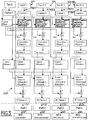
- the figure 3 represents a block diagram of the operation of the DSP processor.
- Top 1 is dedicated to the motor 1 and its sensor C.
- a capture (reading) of the counter is triggered. This value is stored as a Capture1 variable.
- the value of Capture1 in Capture1p index shift
- the value of the counter can then be stored in the Capture1 variable (and so on).
- Top 2 is dedicated to the motor 2 and its sensor C.
- a capture (reading) of the counter is triggered. This value is stored as a Capture2 variable.
- the value of Capture2 in Capture2p index shift
- the value of the counter can then be stored in the Capture2 variable (and so on).
- Top 3 is dedicated to the motor 3 and its sensor C.
- a capture (reading) of the counter is triggered. This value is stored as a Capture3 variable.
- the value of the counter can then be stored in the Capture3 variable (and so on).
- Top 4 is dedicated to the motor 4 and its sensor C. When the signal of the sensor C goes from 0 to 1, a capture of the counter is triggered. This value is stored as a Capture4 variable. See you next time capture, we store the value of Capture4 in Capture4p (index shift), the value of the counter can then be stored in the variable Capture4 (and so on).
- the Speed Error signals 1 to 4 allow direct control of the MT motor of each of the modules (or pairs of modules) to adjust the rotation frequency of the masses to the setpoint.
- the value of the Phase Error signal referenced from 1 to 4 is compared with a phase reference value developed from the reference signal amplitude Fc (t).
- the amplitude of the reference signal is proportional to the force Fz to be generated, and this depends on the phase shift ⁇ .
- the setpoint signal is standardized so that its maximum amplitude A (for example 5V) corresponds to 1.
- the normalized amplitude a is thus between -1 and +1 peak-to-peak.
- This phase can be normalized by dividing its value by 2 ⁇ From the phase reference, speed error and phase error signals, a speed control signal and a phase control signal with proportional and integral correction (PI speed 1 to 4) are conventionally developed. , and PI phase 1 to 4). These signals are summed to form the signal CS 1 .... CS 4 which supplies the circuits PWR 1 to 4 which deliver the signals W1 to W4 for controlling the motors MT1 to MT4.
- the reference position is known, it is known that the first pulse received on the other input of the DSP after a pulse supplied by the reference sensor C corresponds to the first auxiliary sensor (if there are several) and thus so there is no need to assign a particular input to each of the auxiliary sensors.
- Period 1 4 Capture 1 - Capture 1 p and so on for the other modules.
- the difference between the stored values of the first and the second time period is calculated by reducing these periods to the same angular difference for the masses M in rotation.
- a correction of 0 °, 90 °, 180 ° and 270 ° must be applied depending on whether the top is delivered by the main sensor C or one of the auxiliary sensors, for take into account their angular offset with respect to the reference sensor C.
- a periodically reset counter has been used. If this reset (or more generally reset to a given account) takes place between two captures, this must be taken into account by adding to the value of the first catch Capture S and Capture 1 after reset the account L counter corresponding to the reset (see figure 4b ).
- the test of a reset can be Capture S ⁇ Capture Sp for the setpoint signal and Capture 1 ⁇ Capture 1 p and so on for the sensor signals.
- Capture S and Capture 1 to 4 the maximum count of the counter so that the calculated difference (Capture S ⁇ Capture Sp) and (Capture 1 ⁇ Capture 1p), etc ... is correct.
- a frequency setpoint at a frequency lower than the desired operating frequency, for example 5 Hz for operation at 20 Hz. Once the frequency stabilized at the low value (5 Hz) this is increased to obtain the operating frequency, and then the phase setpoint is applied.
- phase difference exceeds ⁇ (180 °), which corresponds to a phase correction greater than 0.5, then, for example, the corresponding motor is delayed (rather than advanced).
Landscapes
- Engineering & Computer Science (AREA)
- Physics & Mathematics (AREA)
- General Physics & Mathematics (AREA)
- Automation & Control Theory (AREA)
- Mechanical Engineering (AREA)
- Control Of Electric Motors In General (AREA)
- Gyroscopes (AREA)
- Magnetic Bearings And Hydrostatic Bearings (AREA)
- Apparatuses For Generation Of Mechanical Vibrations (AREA)
- Testing Of Balance (AREA)
- Measuring Volume Flow (AREA)
- Measurement Of Length, Angles, Or The Like Using Electric Or Magnetic Means (AREA)
Applications Claiming Priority (2)
| Application Number | Priority Date | Filing Date | Title |
|---|---|---|---|
| FR0300512 | 2003-01-17 | ||
| FR0300512A FR2850042B1 (fr) | 2003-01-17 | 2003-01-17 | Generateur d'efforts dynamiques a balourd |
Publications (2)
| Publication Number | Publication Date |
|---|---|
| EP1439010A1 EP1439010A1 (fr) | 2004-07-21 |
| EP1439010B1 true EP1439010B1 (fr) | 2018-11-14 |
Family
ID=32524971
Family Applications (1)
| Application Number | Title | Priority Date | Filing Date |
|---|---|---|---|
| EP03293214.7A Expired - Lifetime EP1439010B1 (fr) | 2003-01-17 | 2003-12-18 | Générateur d'efforts dynamiques à balourd |
Country Status (9)
| Country | Link |
|---|---|
| US (1) | US7132817B2 (tr) |
| EP (1) | EP1439010B1 (tr) |
| JP (1) | JP4362711B2 (tr) |
| CN (1) | CN100388986C (tr) |
| BR (1) | BR0305989A (tr) |
| CA (1) | CA2453699C (tr) |
| FR (1) | FR2850042B1 (tr) |
| MX (1) | MXPA04000529A (tr) |
| TR (1) | TR201901187T4 (tr) |
Families Citing this family (15)
| Publication number | Priority date | Publication date | Assignee | Title |
|---|---|---|---|---|
| CN101022994B (zh) | 2004-08-30 | 2012-07-04 | 洛德公司 | 直升飞机振动控制系统和消除振动的旋转力发生器 |
| US8267652B2 (en) | 2004-08-30 | 2012-09-18 | Lord Corporation | Helicopter hub mounted vibration control and circular force generation systems for canceling vibrations |
| US7722322B2 (en) | 2004-08-30 | 2010-05-25 | Lord Corporation | Computer system and program product for controlling vibrations |
| US8162606B2 (en) | 2004-08-30 | 2012-04-24 | Lord Corporation | Helicopter hub mounted vibration control and circular force generation systems for canceling vibrations |
| FR2886077B1 (fr) * | 2005-05-19 | 2007-08-03 | Snr Roulements Sa | Procede de discrimination d'une impulsion de reference |
| FR2894040B1 (fr) * | 2005-11-28 | 2011-10-21 | Eurocopter France | Dispositif d'asservissement pour un vibrateur a rotors desequilibres. |
| EP2024660B1 (en) * | 2006-06-01 | 2012-04-11 | Lord Corporation | Rotary wing aircraft rotating machinery vibration control system |
| DE102006059189B4 (de) * | 2006-12-15 | 2008-08-14 | Tutech Innovation Gmbh | Vorrichtung zur Schwingungskontrolle einer Konstruktion |
| WO2008145122A1 (en) * | 2007-05-31 | 2008-12-04 | Vestas Wind Systems A/S | A system for damping oscillations in a structure |
| EP2572983B1 (en) | 2007-10-25 | 2015-03-04 | Lord Corporation | Distributed active vibration control systems |
| JP2013074405A (ja) * | 2011-09-27 | 2013-04-22 | Nec Saitama Ltd | モバイル機器 |
| US20150321753A1 (en) * | 2012-12-12 | 2015-11-12 | Paul R. Black | Circular force generator devices, systems, and methods for use in an active vibration control system |
| US20160009386A1 (en) * | 2013-03-20 | 2016-01-14 | Lord Corporation | Low moment force generator devices and methods |
| CN108519204B (zh) * | 2018-04-11 | 2019-11-26 | 中国科学院工程热物理研究所 | 一种三维振动模态可调的叶片激振器及其设计方法 |
| US10767725B2 (en) * | 2018-07-25 | 2020-09-08 | Denso International America, Inc. | Amplitude-modulating vibrator for predictive maintenance modeling |
Family Cites Families (15)
| Publication number | Priority date | Publication date | Assignee | Title |
|---|---|---|---|---|
| US3640508A (en) * | 1969-06-25 | 1972-02-08 | All American Tool & Mfg Co | Vibration force generator |
| EP0092014A1 (de) * | 1982-04-21 | 1983-10-26 | Losenhausen Maschinenbau AG& Co Kommanditgesellschaft | Verstelleinrichtung für Unwucht-Schwingungserzeuger |
| EP0337040A1 (fr) * | 1988-04-14 | 1989-10-18 | Gec Alsthom Sa | Dispositif pour compenser une force vibratoire ou un couple vibratoire créé par un corps |
| US5099430A (en) * | 1988-10-28 | 1992-03-24 | Joseph Hirsch | Method and apparatus for continuously suppressing unwanted rotational phenomena in a rotating body |
| US5172599A (en) * | 1991-05-15 | 1992-12-22 | Woltering Howard M | Vibratory device |
| FR2685571A1 (fr) * | 1991-12-20 | 1993-06-25 | Valeo Systemes Dessuyage | Rotor a aimants permanents, et machine magneto-dynamique, comme un moteur sans collecteur, equipee d'un tel rotor. |
| US5400256A (en) * | 1992-01-21 | 1995-03-21 | The Charles Stark Draper Laboratory, Inc. | Frequency tracking adaptive synchronous vibration suppression apparatus |
| DE4407013A1 (de) * | 1994-03-03 | 1995-09-07 | Gedib Ingbuero Innovation | Verstelleinrichtung mit Regeleinrichtung für einen Unwucht-Richtschwinger mit verstellbarem Fliehmoment und Verfahren für den Betrieb der Regeleinrichtung |
| DE4434221C2 (de) * | 1994-09-26 | 1996-08-29 | Netter Gmbh | Motorgetriebener Unwuchtvibrator |
| US5757662A (en) * | 1994-11-29 | 1998-05-26 | Balance Dynamics, Inc. | Eletromagnetically actuated rotating machine unbalance compensator |
| GB2305488B (en) * | 1995-09-21 | 1999-04-28 | Moog Inc | Modular vibratory force generator, and method of operating same |
| US5825663A (en) * | 1996-11-04 | 1998-10-20 | Gec-Marconi Aerospace Inc. | Vibration control system |
| FR2772805B1 (fr) * | 1997-12-24 | 2000-02-25 | Procedes Tech Const | Dispositif pour la commande asservie de l'amplitude des vibrations d'un vibrateur a moment variable |
| EP1076602A1 (de) * | 1998-05-08 | 2001-02-21 | Gedib Ingenieurbüro Und Innovationsberatung Gmbh | Verstelleinrichtung zur verstellung des resultierenden statischen momentes von unwucht-vibratoren |
| DE10051391B4 (de) * | 1999-10-18 | 2013-02-07 | Tokai Rubber Industries, Ltd. | Vibrator-Steuerverfahren und Vibrator |
-
2003
- 2003-01-17 FR FR0300512A patent/FR2850042B1/fr not_active Expired - Fee Related
- 2003-02-19 US US10/369,439 patent/US7132817B2/en not_active Expired - Lifetime
- 2003-12-18 EP EP03293214.7A patent/EP1439010B1/fr not_active Expired - Lifetime
- 2003-12-18 TR TR2019/01187T patent/TR201901187T4/tr unknown
- 2003-12-19 CA CA2453699A patent/CA2453699C/en not_active Expired - Fee Related
- 2003-12-30 BR BR0305989-8A patent/BR0305989A/pt not_active Application Discontinuation
-
2004
- 2004-01-15 CN CNB2004100018976A patent/CN100388986C/zh not_active Expired - Fee Related
- 2004-01-16 JP JP2004008630A patent/JP4362711B2/ja not_active Expired - Fee Related
- 2004-01-16 MX MXPA04000529A patent/MXPA04000529A/es active IP Right Grant
Non-Patent Citations (1)
| Title |
|---|
| None * |
Also Published As
| Publication number | Publication date |
|---|---|
| CN100388986C (zh) | 2008-05-21 |
| JP2004223511A (ja) | 2004-08-12 |
| CA2453699A1 (en) | 2004-07-17 |
| EP1439010A1 (fr) | 2004-07-21 |
| MXPA04000529A (es) | 2009-06-10 |
| JP4362711B2 (ja) | 2009-11-11 |
| US7132817B2 (en) | 2006-11-07 |
| CN1517156A (zh) | 2004-08-04 |
| FR2850042A1 (fr) | 2004-07-23 |
| US20040140789A1 (en) | 2004-07-22 |
| TR201901187T4 (tr) | 2019-02-21 |
| FR2850042B1 (fr) | 2007-05-04 |
| BR0305989A (pt) | 2005-02-09 |
| CA2453699C (en) | 2010-10-19 |
Similar Documents
| Publication | Publication Date | Title |
|---|---|---|
| EP1439010B1 (fr) | Générateur d'efforts dynamiques à balourd | |
| FR2551552A1 (fr) | Detecteur de vitesse angulaire utilisant deux accelerometres vibrants fixes a un parrallelogramme | |
| FR3077638A1 (fr) | Procédé pour mesurer le balourd de rotors à arbre élastique au moyen de capteurs de déplacement | |
| EP1002716A1 (fr) | Procédé et dispositif de pilotage de l'attitude d'un satellite | |
| FR2946745A1 (fr) | Banc de charge dynamique. | |
| EP2338027B1 (fr) | Mesure gyroscopique par un gyroscope vibrant | |
| EP0505976A1 (fr) | Dispositif pour compenser une force vibratoire ou un couple vibratoire subi par une corps | |
| FR2955388A1 (fr) | Appareil de detection d'angle de rotation, equipement de machine electrique rotative, et equipement de direction assistee electrique | |
| EP2789976B1 (fr) | Circuit électronique d'entraînement d'un dispositif à résonateur du type MEMS, et procédé pour sa mise en action | |
| EP1579176B1 (fr) | Gyromètre vibrant avec asservissement de la fréquence de détection sur la fréquence d'excitation | |
| FR2984497A1 (fr) | Procede et dispositif de determination du couple d'un moteur electrique et ensemble de moteur avec un moteur electrique | |
| JP5259598B2 (ja) | 微小電気機械センサ及び微小電気機械センサの操作方法 | |
| EP0812059B1 (fr) | Procédé de contrôle commande d'une machine tournante, dispositif d'asservissement pour mettre en oeuvre ledit procédé et application du dispositif à une machine tournante | |
| WO2000045127A1 (fr) | Gyroscope vibrant | |
| FR2502771A1 (fr) | Ensemble gyroscopique de reference pour vehicule | |
| FR2620243A1 (fr) | Procede de reacquisition de la position de tangage d'un satellite terrestre | |
| FR2575835A1 (fr) | Compensation d'acceleration lineaire pour multidetecteur | |
| EP2942287A1 (fr) | Procédé de commande d'un système de contrôle d'attitude et système de contrôle d'attitude d'un véhicule spatial | |
| FR2676120A1 (fr) | Procede et dispositif de detection de force et de position de desequilibre par modulation de frequence. | |
| FR2551554A1 (fr) | Dispositif de mesure de la force inertielle specifique et de la vitesse angulaire d'un corps mobile | |
| EP0702451A1 (fr) | Dispositif de commande d'un moteur synchrone | |
| EP0388845A1 (fr) | Système de commande vectorielle pour moteur électrique asynchrone à cage | |
| FR2958029A1 (fr) | Procede de mesure angulaire au moyen d'un capteur vibrant auquel sont appliquees des commandes modulees | |
| EP1586858A1 (fr) | Procédé de commande en push-pull d'un gyrometre à laser | |
| EP0520897B1 (fr) | Dispositif de commande d'un indicateur électrique à bobines croisées, de type logomètre |
Legal Events
| Date | Code | Title | Description |
|---|---|---|---|
| PUAI | Public reference made under article 153(3) epc to a published international application that has entered the european phase |
Free format text: ORIGINAL CODE: 0009012 |
|
| AK | Designated contracting states |
Kind code of ref document: A1 Designated state(s): AT BE BG CH CY CZ DE DK EE ES FI FR GB GR HU IE IT LI LU MC NL PT RO SE SI SK TR |
|
| AX | Request for extension of the european patent |
Extension state: AL LT LV MK |
|
| 17P | Request for examination filed |
Effective date: 20040810 |
|
| AKX | Designation fees paid |
Designated state(s): AT BE BG CH CY CZ DE DK EE ES FI FR GB GR HU IE IT LI LU MC NL PT RO SE SI SK TR |
|
| GRAP | Despatch of communication of intention to grant a patent |
Free format text: ORIGINAL CODE: EPIDOSNIGR1 |
|
| INTG | Intention to grant announced |
Effective date: 20180606 |
|
| GRAS | Grant fee paid |
Free format text: ORIGINAL CODE: EPIDOSNIGR3 |
|
| GRAA | (expected) grant |
Free format text: ORIGINAL CODE: 0009210 |
|
| AK | Designated contracting states |
Kind code of ref document: B1 Designated state(s): AT BE BG CH CY CZ DE DK EE ES FI FR GB GR HU IE IT LI LU MC NL PT RO SE SI SK TR |
|
| REG | Reference to a national code |
Ref country code: GB Ref legal event code: FG4D Free format text: NOT ENGLISH |
|
| REG | Reference to a national code |
Ref country code: CH Ref legal event code: EP Ref country code: AT Ref legal event code: REF Ref document number: 1064211 Country of ref document: AT Kind code of ref document: T Effective date: 20181115 |
|
| REG | Reference to a national code |
Ref country code: DE Ref legal event code: R096 Ref document number: 60351627 Country of ref document: DE |
|
| REG | Reference to a national code |
Ref country code: IE Ref legal event code: FG4D Free format text: LANGUAGE OF EP DOCUMENT: FRENCH |
|
| REG | Reference to a national code |
Ref country code: CH Ref legal event code: PK Free format text: RECTIFICATIONS |
|
| RIC2 | Information provided on ipc code assigned after grant |
Ipc: B06B 1/16 20060101AFI20040429BHEP Ipc: G05D 19/02 20060101ALI20040429BHEP |
|
| REG | Reference to a national code |
Ref country code: NL Ref legal event code: MP Effective date: 20181114 |
|
| REG | Reference to a national code |
Ref country code: AT Ref legal event code: MK05 Ref document number: 1064211 Country of ref document: AT Kind code of ref document: T Effective date: 20181114 |
|
| PG25 | Lapsed in a contracting state [announced via postgrant information from national office to epo] |
Ref country code: ES Free format text: LAPSE BECAUSE OF FAILURE TO SUBMIT A TRANSLATION OF THE DESCRIPTION OR TO PAY THE FEE WITHIN THE PRESCRIBED TIME-LIMIT Effective date: 20181114 Ref country code: AT Free format text: LAPSE BECAUSE OF FAILURE TO SUBMIT A TRANSLATION OF THE DESCRIPTION OR TO PAY THE FEE WITHIN THE PRESCRIBED TIME-LIMIT Effective date: 20181114 Ref country code: BG Free format text: LAPSE BECAUSE OF FAILURE TO SUBMIT A TRANSLATION OF THE DESCRIPTION OR TO PAY THE FEE WITHIN THE PRESCRIBED TIME-LIMIT Effective date: 20190214 Ref country code: FI Free format text: LAPSE BECAUSE OF FAILURE TO SUBMIT A TRANSLATION OF THE DESCRIPTION OR TO PAY THE FEE WITHIN THE PRESCRIBED TIME-LIMIT Effective date: 20181114 |
|
| PG25 | Lapsed in a contracting state [announced via postgrant information from national office to epo] |
Ref country code: SE Free format text: LAPSE BECAUSE OF FAILURE TO SUBMIT A TRANSLATION OF THE DESCRIPTION OR TO PAY THE FEE WITHIN THE PRESCRIBED TIME-LIMIT Effective date: 20181114 Ref country code: NL Free format text: LAPSE BECAUSE OF FAILURE TO SUBMIT A TRANSLATION OF THE DESCRIPTION OR TO PAY THE FEE WITHIN THE PRESCRIBED TIME-LIMIT Effective date: 20181114 Ref country code: PT Free format text: LAPSE BECAUSE OF FAILURE TO SUBMIT A TRANSLATION OF THE DESCRIPTION OR TO PAY THE FEE WITHIN THE PRESCRIBED TIME-LIMIT Effective date: 20190314 Ref country code: GR Free format text: LAPSE BECAUSE OF FAILURE TO SUBMIT A TRANSLATION OF THE DESCRIPTION OR TO PAY THE FEE WITHIN THE PRESCRIBED TIME-LIMIT Effective date: 20190215 |
|
| PG25 | Lapsed in a contracting state [announced via postgrant information from national office to epo] |
Ref country code: CZ Free format text: LAPSE BECAUSE OF FAILURE TO SUBMIT A TRANSLATION OF THE DESCRIPTION OR TO PAY THE FEE WITHIN THE PRESCRIBED TIME-LIMIT Effective date: 20181114 Ref country code: DK Free format text: LAPSE BECAUSE OF FAILURE TO SUBMIT A TRANSLATION OF THE DESCRIPTION OR TO PAY THE FEE WITHIN THE PRESCRIBED TIME-LIMIT Effective date: 20181114 |
|
| REG | Reference to a national code |
Ref country code: CH Ref legal event code: PL |
|
| REG | Reference to a national code |
Ref country code: DE Ref legal event code: R097 Ref document number: 60351627 Country of ref document: DE |
|
| PG25 | Lapsed in a contracting state [announced via postgrant information from national office to epo] |
Ref country code: LU Free format text: LAPSE BECAUSE OF NON-PAYMENT OF DUE FEES Effective date: 20181218 Ref country code: RO Free format text: LAPSE BECAUSE OF FAILURE TO SUBMIT A TRANSLATION OF THE DESCRIPTION OR TO PAY THE FEE WITHIN THE PRESCRIBED TIME-LIMIT Effective date: 20181114 Ref country code: EE Free format text: LAPSE BECAUSE OF FAILURE TO SUBMIT A TRANSLATION OF THE DESCRIPTION OR TO PAY THE FEE WITHIN THE PRESCRIBED TIME-LIMIT Effective date: 20181114 Ref country code: MC Free format text: LAPSE BECAUSE OF FAILURE TO SUBMIT A TRANSLATION OF THE DESCRIPTION OR TO PAY THE FEE WITHIN THE PRESCRIBED TIME-LIMIT Effective date: 20181114 Ref country code: SK Free format text: LAPSE BECAUSE OF FAILURE TO SUBMIT A TRANSLATION OF THE DESCRIPTION OR TO PAY THE FEE WITHIN THE PRESCRIBED TIME-LIMIT Effective date: 20181114 |
|
| REG | Reference to a national code |
Ref country code: IE Ref legal event code: MM4A |
|
| PLBE | No opposition filed within time limit |
Free format text: ORIGINAL CODE: 0009261 |
|
| STAA | Information on the status of an ep patent application or granted ep patent |
Free format text: STATUS: NO OPPOSITION FILED WITHIN TIME LIMIT |
|
| REG | Reference to a national code |
Ref country code: BE Ref legal event code: MM Effective date: 20181231 |
|
| 26N | No opposition filed |
Effective date: 20190815 |
|
| GBPC | Gb: european patent ceased through non-payment of renewal fee |
Effective date: 20190214 |
|
| PG25 | Lapsed in a contracting state [announced via postgrant information from national office to epo] |
Ref country code: IE Free format text: LAPSE BECAUSE OF NON-PAYMENT OF DUE FEES Effective date: 20181218 Ref country code: SI Free format text: LAPSE BECAUSE OF FAILURE TO SUBMIT A TRANSLATION OF THE DESCRIPTION OR TO PAY THE FEE WITHIN THE PRESCRIBED TIME-LIMIT Effective date: 20181114 |
|
| PG25 | Lapsed in a contracting state [announced via postgrant information from national office to epo] |
Ref country code: BE Free format text: LAPSE BECAUSE OF NON-PAYMENT OF DUE FEES Effective date: 20181231 |
|
| PG25 | Lapsed in a contracting state [announced via postgrant information from national office to epo] |
Ref country code: CH Free format text: LAPSE BECAUSE OF NON-PAYMENT OF DUE FEES Effective date: 20181231 Ref country code: LI Free format text: LAPSE BECAUSE OF NON-PAYMENT OF DUE FEES Effective date: 20181231 |
|
| PG25 | Lapsed in a contracting state [announced via postgrant information from national office to epo] |
Ref country code: GB Free format text: LAPSE BECAUSE OF NON-PAYMENT OF DUE FEES Effective date: 20190214 |
|
| PG25 | Lapsed in a contracting state [announced via postgrant information from national office to epo] |
Ref country code: CY Free format text: LAPSE BECAUSE OF FAILURE TO SUBMIT A TRANSLATION OF THE DESCRIPTION OR TO PAY THE FEE WITHIN THE PRESCRIBED TIME-LIMIT Effective date: 20181114 Ref country code: HU Free format text: LAPSE BECAUSE OF FAILURE TO SUBMIT A TRANSLATION OF THE DESCRIPTION OR TO PAY THE FEE WITHIN THE PRESCRIBED TIME-LIMIT; INVALID AB INITIO Effective date: 20031218 |
|
| PGFP | Annual fee paid to national office [announced via postgrant information from national office to epo] |
Ref country code: DE Payment date: 20201211 Year of fee payment: 18 Ref country code: FR Payment date: 20201125 Year of fee payment: 18 |
|
| PGFP | Annual fee paid to national office [announced via postgrant information from national office to epo] |
Ref country code: IT Payment date: 20201224 Year of fee payment: 18 |
|
| PGFP | Annual fee paid to national office [announced via postgrant information from national office to epo] |
Ref country code: TR Payment date: 20201217 Year of fee payment: 18 |
|
| REG | Reference to a national code |
Ref country code: DE Ref legal event code: R119 Ref document number: 60351627 Country of ref document: DE |
|
| PG25 | Lapsed in a contracting state [announced via postgrant information from national office to epo] |
Ref country code: DE Free format text: LAPSE BECAUSE OF NON-PAYMENT OF DUE FEES Effective date: 20220701 |
|
| PG25 | Lapsed in a contracting state [announced via postgrant information from national office to epo] |
Ref country code: FR Free format text: LAPSE BECAUSE OF NON-PAYMENT OF DUE FEES Effective date: 20211231 |
|
| PG25 | Lapsed in a contracting state [announced via postgrant information from national office to epo] |
Ref country code: IT Free format text: LAPSE BECAUSE OF NON-PAYMENT OF DUE FEES Effective date: 20211218 |