EP1437468A1 - Movable partition wall - Google Patents
Movable partition wall Download PDFInfo
- Publication number
- EP1437468A1 EP1437468A1 EP04000304A EP04000304A EP1437468A1 EP 1437468 A1 EP1437468 A1 EP 1437468A1 EP 04000304 A EP04000304 A EP 04000304A EP 04000304 A EP04000304 A EP 04000304A EP 1437468 A1 EP1437468 A1 EP 1437468A1
- Authority
- EP
- European Patent Office
- Prior art keywords
- mobile partition
- partition according
- control unit
- wall element
- drive
- Prior art date
- Legal status (The legal status is an assumption and is not a legal conclusion. Google has not performed a legal analysis and makes no representation as to the accuracy of the status listed.)
- Withdrawn
Links
- 238000005192 partition Methods 0.000 title claims description 32
- 238000001514 detection method Methods 0.000 claims description 2
- 230000008878 coupling Effects 0.000 claims 1
- 238000010168 coupling process Methods 0.000 claims 1
- 238000005859 coupling reaction Methods 0.000 claims 1
- 238000007789 sealing Methods 0.000 description 5
- 230000008901 benefit Effects 0.000 description 3
- 238000000034 method Methods 0.000 description 3
- 235000014676 Phragmites communis Nutrition 0.000 description 2
- 230000007246 mechanism Effects 0.000 description 2
- 229910052751 metal Inorganic materials 0.000 description 2
- 239000002184 metal Substances 0.000 description 2
- 229910000831 Steel Inorganic materials 0.000 description 1
- 229910052782 aluminium Inorganic materials 0.000 description 1
- XAGFODPZIPBFFR-UHFFFAOYSA-N aluminium Chemical compound [Al] XAGFODPZIPBFFR-UHFFFAOYSA-N 0.000 description 1
- 230000005540 biological transmission Effects 0.000 description 1
- 239000004020 conductor Substances 0.000 description 1
- 238000010276 construction Methods 0.000 description 1
- 230000002950 deficient Effects 0.000 description 1
- 230000005611 electricity Effects 0.000 description 1
- 238000005516 engineering process Methods 0.000 description 1
- 239000011521 glass Substances 0.000 description 1
- 230000006872 improvement Effects 0.000 description 1
- 238000009434 installation Methods 0.000 description 1
- 230000010354 integration Effects 0.000 description 1
- 238000012423 maintenance Methods 0.000 description 1
- 238000012986 modification Methods 0.000 description 1
- 230000004048 modification Effects 0.000 description 1
- 230000008569 process Effects 0.000 description 1
- 238000009420 retrofitting Methods 0.000 description 1
- 238000000638 solvent extraction Methods 0.000 description 1
- 239000010959 steel Substances 0.000 description 1
- 239000000725 suspension Substances 0.000 description 1
- 239000002023 wood Substances 0.000 description 1
Images
Classifications
-
- E—FIXED CONSTRUCTIONS
- E04—BUILDING
- E04B—GENERAL BUILDING CONSTRUCTIONS; WALLS, e.g. PARTITIONS; ROOFS; FLOORS; CEILINGS; INSULATION OR OTHER PROTECTION OF BUILDINGS
- E04B2/00—Walls, e.g. partitions, for buildings; Wall construction with regard to insulation; Connections specially adapted to walls
- E04B2/74—Removable non-load-bearing partitions; Partitions with a free upper edge
- E04B2/82—Removable non-load-bearing partitions; Partitions with a free upper edge characterised by the manner in which edges are connected to the building; Means therefor; Special details of easily-removable partitions as far as related to the connection with other parts of the building
- E04B2/827—Partitions constituted of sliding panels
-
- E—FIXED CONSTRUCTIONS
- E05—LOCKS; KEYS; WINDOW OR DOOR FITTINGS; SAFES
- E05F—DEVICES FOR MOVING WINGS INTO OPEN OR CLOSED POSITION; CHECKS FOR WINGS; WING FITTINGS NOT OTHERWISE PROVIDED FOR, CONCERNED WITH THE FUNCTIONING OF THE WING
- E05F15/00—Power-operated mechanisms for wings
- E05F15/60—Power-operated mechanisms for wings using electrical actuators
- E05F15/603—Power-operated mechanisms for wings using electrical actuators using rotary electromotors
- E05F15/632—Power-operated mechanisms for wings using electrical actuators using rotary electromotors for horizontally-sliding wings
- E05F15/635—Power-operated mechanisms for wings using electrical actuators using rotary electromotors for horizontally-sliding wings operated by push-pull mechanisms, e.g. flexible or rigid rack-and-pinion arrangements
-
- E—FIXED CONSTRUCTIONS
- E05—LOCKS; KEYS; WINDOW OR DOOR FITTINGS; SAFES
- E05F—DEVICES FOR MOVING WINGS INTO OPEN OR CLOSED POSITION; CHECKS FOR WINGS; WING FITTINGS NOT OTHERWISE PROVIDED FOR, CONCERNED WITH THE FUNCTIONING OF THE WING
- E05F15/00—Power-operated mechanisms for wings
- E05F15/60—Power-operated mechanisms for wings using electrical actuators
- E05F15/603—Power-operated mechanisms for wings using electrical actuators using rotary electromotors
- E05F15/632—Power-operated mechanisms for wings using electrical actuators using rotary electromotors for horizontally-sliding wings
- E05F15/643—Power-operated mechanisms for wings using electrical actuators using rotary electromotors for horizontally-sliding wings operated by flexible elongated pulling elements, e.g. belts, chains or cables
-
- E—FIXED CONSTRUCTIONS
- E05—LOCKS; KEYS; WINDOW OR DOOR FITTINGS; SAFES
- E05Y—INDEXING SCHEME RELATING TO HINGES OR OTHER SUSPENSION DEVICES FOR DOORS, WINDOWS OR WINGS AND DEVICES FOR MOVING WINGS INTO OPEN OR CLOSED POSITION, CHECKS FOR WINGS AND WING FITTINGS NOT OTHERWISE PROVIDED FOR, CONCERNED WITH THE FUNCTIONING OF THE WING
- E05Y2201/00—Constructional elements; Accessories therefore
- E05Y2201/40—Motors; Magnets; Springs; Weights; Accessories therefore
- E05Y2201/43—Motors
- E05Y2201/434—Electromotors; Details thereof
-
- E—FIXED CONSTRUCTIONS
- E05—LOCKS; KEYS; WINDOW OR DOOR FITTINGS; SAFES
- E05Y—INDEXING SCHEME RELATING TO HINGES OR OTHER SUSPENSION DEVICES FOR DOORS, WINDOWS OR WINGS AND DEVICES FOR MOVING WINGS INTO OPEN OR CLOSED POSITION, CHECKS FOR WINGS AND WING FITTINGS NOT OTHERWISE PROVIDED FOR, CONCERNED WITH THE FUNCTIONING OF THE WING
- E05Y2400/00—Electronic control; Power supply; Power or signal transmission; User interfaces
- E05Y2400/10—Electronic control
- E05Y2400/30—Electronic control of motors
- E05Y2400/32—Position control, detection or monitoring
- E05Y2400/322—Position control, detection or monitoring by using absolute position sensors
- E05Y2400/328—Position control, detection or monitoring by using absolute position sensors of the linear type
-
- E—FIXED CONSTRUCTIONS
- E05—LOCKS; KEYS; WINDOW OR DOOR FITTINGS; SAFES
- E05Y—INDEXING SCHEME RELATING TO HINGES OR OTHER SUSPENSION DEVICES FOR DOORS, WINDOWS OR WINGS AND DEVICES FOR MOVING WINGS INTO OPEN OR CLOSED POSITION, CHECKS FOR WINGS AND WING FITTINGS NOT OTHERWISE PROVIDED FOR, CONCERNED WITH THE FUNCTIONING OF THE WING
- E05Y2400/00—Electronic control; Power supply; Power or signal transmission; User interfaces
- E05Y2400/10—Electronic control
- E05Y2400/30—Electronic control of motors
- E05Y2400/40—Control units therefore
-
- E—FIXED CONSTRUCTIONS
- E05—LOCKS; KEYS; WINDOW OR DOOR FITTINGS; SAFES
- E05Y—INDEXING SCHEME RELATING TO HINGES OR OTHER SUSPENSION DEVICES FOR DOORS, WINDOWS OR WINGS AND DEVICES FOR MOVING WINGS INTO OPEN OR CLOSED POSITION, CHECKS FOR WINGS AND WING FITTINGS NOT OTHERWISE PROVIDED FOR, CONCERNED WITH THE FUNCTIONING OF THE WING
- E05Y2400/00—Electronic control; Power supply; Power or signal transmission; User interfaces
- E05Y2400/60—Power supply; Power or signal transmission
- E05Y2400/65—Power or signal transmission
- E05Y2400/656—Power or signal transmission by travelling contacts
- E05Y2400/658—Power or signal transmission by travelling contacts with current rails
-
- E—FIXED CONSTRUCTIONS
- E05—LOCKS; KEYS; WINDOW OR DOOR FITTINGS; SAFES
- E05Y—INDEXING SCHEME RELATING TO HINGES OR OTHER SUSPENSION DEVICES FOR DOORS, WINDOWS OR WINGS AND DEVICES FOR MOVING WINGS INTO OPEN OR CLOSED POSITION, CHECKS FOR WINGS AND WING FITTINGS NOT OTHERWISE PROVIDED FOR, CONCERNED WITH THE FUNCTIONING OF THE WING
- E05Y2600/00—Mounting or coupling arrangements for elements provided for in this subclass
- E05Y2600/40—Mounting location; Visibility of the elements
- E05Y2600/46—Mounting location; Visibility of the elements in or on the wing
-
- E—FIXED CONSTRUCTIONS
- E05—LOCKS; KEYS; WINDOW OR DOOR FITTINGS; SAFES
- E05Y—INDEXING SCHEME RELATING TO HINGES OR OTHER SUSPENSION DEVICES FOR DOORS, WINDOWS OR WINGS AND DEVICES FOR MOVING WINGS INTO OPEN OR CLOSED POSITION, CHECKS FOR WINGS AND WING FITTINGS NOT OTHERWISE PROVIDED FOR, CONCERNED WITH THE FUNCTIONING OF THE WING
- E05Y2800/00—Details, accessories and auxiliary operations not otherwise provided for
- E05Y2800/20—Combinations of elements
- E05Y2800/21—Combinations of elements of identical elements, e.g. of identical compression springs
-
- E—FIXED CONSTRUCTIONS
- E05—LOCKS; KEYS; WINDOW OR DOOR FITTINGS; SAFES
- E05Y—INDEXING SCHEME RELATING TO HINGES OR OTHER SUSPENSION DEVICES FOR DOORS, WINDOWS OR WINGS AND DEVICES FOR MOVING WINGS INTO OPEN OR CLOSED POSITION, CHECKS FOR WINGS AND WING FITTINGS NOT OTHERWISE PROVIDED FOR, CONCERNED WITH THE FUNCTIONING OF THE WING
- E05Y2800/00—Details, accessories and auxiliary operations not otherwise provided for
- E05Y2800/74—Specific positions
- E05Y2800/742—Specific positions abnormal
- E05Y2800/748—Specific positions abnormal end
-
- E—FIXED CONSTRUCTIONS
- E05—LOCKS; KEYS; WINDOW OR DOOR FITTINGS; SAFES
- E05Y—INDEXING SCHEME RELATING TO HINGES OR OTHER SUSPENSION DEVICES FOR DOORS, WINDOWS OR WINGS AND DEVICES FOR MOVING WINGS INTO OPEN OR CLOSED POSITION, CHECKS FOR WINGS AND WING FITTINGS NOT OTHERWISE PROVIDED FOR, CONCERNED WITH THE FUNCTIONING OF THE WING
- E05Y2900/00—Application of doors, windows, wings or fittings thereof
- E05Y2900/10—Application of doors, windows, wings or fittings thereof for buildings or parts thereof
- E05Y2900/13—Application of doors, windows, wings or fittings thereof for buildings or parts thereof characterised by the type of wing
- E05Y2900/142—Partition walls
Definitions
- the present invention relates to a mobile partition according to the preamble of claim 1.
- partitions can be used for a wide variety of purposes.
- the individual wall elements can be closed Panel, for example made of wood or metal, or made of a translucent pane, for example made of glass.
- Such a partition can be designed to divide a large space become.
- the mobile partition consists of independent, motorized movable wall elements, preferably with a torsionally rigid Frames are formed.
- the wall elements can also designed as a rotating wing, swing wing or moving automatic doors his. All wall elements can move out of the partition axis and parked in a space-saving place.
- each Wall element is at one or two points by means of carriages in a ceiling fixed track can be moved. For horizontal sealing each wall element becomes a final profile against the Running track and a finishing profile pressed against the floor.
- each Wall element can be controlled independently and fully automatically can, wherein each wall element has a control unit that the Power supply and control of the two assigned to each wall element Drives.
- One drive is used for the horizontal movement of the wall element and one drive for vertical bracing the final profiles.
- the control unit is arranged via busbars arranged in the running rail supplied with the necessary electrical energy. Are there Pantograph on one of the two carriages of a wall element arranged, the extending in the suspension of the wall element Lines are connected to the control unit.
- the control unit is connected to the two drives via electrical cables, where position sensors serve as control parameters to determine the sequence of operations to determine the drives and their direction of movement. This principle simplifies the line routing and makes it fully automatic driven wall elements created. Through the combination and integration of the drive controls in a control unit created an electrically and spatially optimized solution. This eliminates the two previously known independent control systems.
- the position sensors are on the one hand on the vertical front side of each Wall element arranged to detect the horizontal position and on the other hand in a mechanism that actuates the end profiles, preferably a pair of scissors, arranged around the position of the end profiles to detect.
- a mechanism that actuates the end profiles preferably a pair of scissors, arranged around the position of the end profiles to detect.
- Another position encoder can optionally position one in the wall element Detect the integrated door to prevent it from being opened Condition of the door the wall element is moved.
- the position sensors described above can be mechanical, electrical or be realized optically. Magnetically working elements are advantageous, z. B. Reed contacts, since they work without contact. Such elements can be completely encapsulated and are therefore insensitive against external influences. They are also at the installation site no adjustment measures required.
- the control unit is implemented in the form of a printed circuit board is equipped on one side, with the supplied lines from the position sensors or the drives are connected via coded connectors become. This is a simple assembly on the one hand and a defective units can be easily replaced.
- the control unit is preferably in the vertical frame of the Wall element arranged, since here the corresponding side member as Mounting base can be used and the control unit protected and is arranged vibration-free.
- This arrangement also has the advantage that the position transmitter to be arranged lengthways directly in the control unit can be integrated and by an appropriate Opening in the side member with the corresponding switch contact of the adjacent wall element interacts.
- an emergency opening device is implemented in each wall element.
- the drive for the horizontal movement of the wall element is on one the two carriages arranged and consists of an electric motor, wherein the drive axis is provided with means that a Active connection with an attack surface formed along the running rail has a movability of the individual wall element allows.
- a pinion / toothed belt combination or a friction wheel drive is suitable for such an active connection.
- the drive for bracing the end profiles is on a central one Cross member arranged within the wall element and via a deflecting Mechanics, preferably a pair of scissors, with the ground and ceiling profiles that can be braced on the ceiling.
- a deflecting Mechanics preferably a pair of scissors
- DC motors which are sufficient Provide driving force and due to their small dimensions take up little space.
- the vertically movable end profiles are on the horizontal edges the frame of each wall element arranged and at rest arranged concealed within the frame. Furthermore located restoring elements in the form of springs in the wall element.
- the entire frame construction is constructed so that cross and Longitudinal beams the actual load-bearing and connecting characteristics for have the cover plates and the mechanical in / on the cross members Functional parts are arranged for moving the end profiles.
- This functionally separate and possibly also physically separate structure of the frame basically simplifies assembly and maintenance the mechanical and the electrical system due to improved Accessibility.
- Another improvement in this regard is created by a modularity of mechanical and electrical systems, In addition, retrofitting is possible, provided that a suitable profile structure is available.
- a mobile partition 1 is independent of a plurality of tabular ones movable wall elements 2 assembled and for Room partitioning or suitable as an external closure. All wall elements 2 can from a space-saving parking position, a so-called Station, driven into the partition axis and braced there.
- Each of these wall elements 2 consists of the exemplary embodiment a torsion-resistant frame 3 made of metal, in particular steel and / or aluminum, and two spaced apart Cover plates 4.
- the frame 3 of each wall element 2 has vertical Sides side members 5 and on horizontal sides cross members 6 and 7. Furthermore, there is a further cross member 8 in the middle between the long members 5 attached.
- On the upper cross member 6 are two carriages 9 and 10 arranged, by means of which the wall element 2 in a ceiling attached track 11 is movable.
- a pin 12 is arranged, by means of which the wall element 2 in a Not shown rail is guided on the bottom.
- each wall element 2 For horizontal sealing of the cross members 6, 7 of each wall element 2 each have an end profile 13 against the running rail 11 and in each case one end profile 14 pressed against the floor, in the unactuated Condition of the end profiles 13, 14 covered in the respective Cross members 6, 7 are arranged.
- the end profiles 13, 14 are with provided flexible sealing strips, not shown, intended for this are pressed against the running rail 11 or ceiling and the floor become.
- Both end profiles 13, 14 are mechanically connected to the central cross member 8 attached scissors 15 and connecting linkage 16 coupled to the respective end profile 13, 14.
- the rods 16 are equipped with restoring elements 17 in the form of springs.
- a drive 18 is attached to the cross member 8, which the Articulated scissors 15 drives.
- the drive 18 is preferably from an electric motor designed as a DC motor.
- the carriage 10 is formed with a further drive 19.
- the connection of the carriage 10 takes place via a hollow tube 20 which in the Wall element 2 is screwed in.
- the drive 19 is preferably from an electric motor designed as a DC motor, which via an operative connection can be moved along the running rail 11.
- the carriage 10 is further provided with current collectors 21, which are electrical conductive with busbars arranged stationary in the running rail 11 22 is in operative connection.
- the pantograph 21, preferably in In the form of sliding contacts, are connected to electrical lines 23, which are guided through the hollow tube 20 in the wall element 2 and die die Control unit 24 arranged in wall element 2 during the method of the wall element 2 with the necessary electrical energy supply.
- the current collectors 21 touch or conduct in an electrically conductive manner along the busbars 22.
- the control unit 24 is on the side member 5 of the wall element 2 attached and realized in the form of a printed circuit board, which is equipped on one side is ( Figure 2).
- the control unit 24 does not refer to various ones designated components, and connectors 25 to 28 for connection the power supply 23, the motor-side control lines 29, 33 and various position sensors 30, 31.
- the connectors 25 to 28 are coded to avoid misplacement, the Plug connection 25 is connected to line 23, which both Power supply and the control line 29 for the drive 19 includes. Via the plug connection 26 and the associated line 33 the drive 18 driven while the connector 27 and the associated line 34 of position transmitter 31 is activated.
- the aforementioned position sensors 30, 31 are non-contact Reed contacts designed that interact with appropriate magnets.
- a position sensor 30 is mounted on the longitudinal beam 5, the the horizontal position of the wall element 2 is detected.
- the Position transmitter 30 integrated directly into the control unit 24 and acts through a corresponding opening in the longitudinal beam 5 with the corresponding one Magnets of a stationary wall termination 32 or one adjacent wall element 2 together.
- Another position encoder 31 is arranged in the joint scissors 15 for positioning to detect the end profiles 13, 14.
- the operation of the mobile partition 1 is described below.
- the individual wall elements are in the unactuated state 2 of the mobile partition 1 space-saving in a so-called, not shown station, which has a track arrangement with the actual Partition axis is connected.
- a first wall element 2 will lead over the running rail 11 brought against a stationary wall termination 32.
- the control unit 24 is powered by the current collector 21 Energy supplied. As long as the position transmitter 30 is open, is the drive 19 from the control unit 24 via the line 23, 29th Electricity supplied so that the wall element 2 against the stationary Wall termination 32 moves. As soon as the position transmitter 30 on the side member 5 is closed, the control unit 24 switches after a time Delay the current on the drive 18 for the bracing of the end profiles 13, 14 ⁇ m. The time delay is required to one sufficient contact pressure against the stationary wall termination 32 to build. As soon as the end profiles 13, 14 over the joint scissors 15 are completely braced, this wall element 2 is from the Control unit 24 switched off by overcurrent detection. When attaching further wall elements 2, the process described is repeated.
- a shaft 35 is outward from each joint scissors 15 led so that in the event of a power failure there a crank 36 manual relaxation of the end profiles 13, 14 are inserted can.
Abstract
Description
Die vorliegende Erfindung betrifft eine mobile Trennwand nach dem Oberbegriff
des Patentanspruches 1.The present invention relates to a mobile partition according to the preamble
of
Derartige Trennwände sind für die verschiedensten Zwecke einsetzbar. Je nach Verwendung können die einzelnen Wandelemente aus einem geschlossenen Paneel, beispielsweise aus Holz oder Metall, oder aber aus einer lichtdurchlässigen Scheibe, beispielsweise aus Glas, bestehen. Mit einer solchen Trennwand kann ein großer Raum unterteilbar gestaltet werden. Auch sind durch Trennwände Geschäftslokale in Einkaufszentren oder Einkaufspassagen von den Durchgangsbereichen abschließbar.Such partitions can be used for a wide variety of purposes. ever After use, the individual wall elements can be closed Panel, for example made of wood or metal, or made of a translucent pane, for example made of glass. With Such a partition can be designed to divide a large space become. There are also business premises in shopping centers thanks to partitions or shopping arcades lockable from the passage areas.
Die DE 31 47 273 A1 zeigt eine mobile Trennwand, deren einzelne Wandelemente deckenseitig geführt und motorisch in horizontaler Richtung verschiebbar sind. An den oberen und unteren horizontalen Abschlüssen jedes Wandelementes sind Dichtleisten angeordnet, die über eine in jedem Wandelement angeordnete Gelenkschere vertikal verfahrbar sind. Jede Gelenkschere wird von einem eigenen Motor innerhalb jedes Wandelementes angetrieben. Nachteilig ist die separate Bestromung und Steuerung der beiden Motoren innerhalb jedes Wandelementes, da hierdurch eine aufwendige Leitungsverlegung und eine komplizierte Steuerungstechnik notwendig ist. Außerdem ist die Anordnung und Kraftübertragung des Fahrmotors äußerst aufwendig realisiert.DE 31 47 273 A1 shows a mobile partition, the individual wall elements guided on the ceiling side and movable in the horizontal direction by motor are. At the top and bottom horizontal ends of each Sealing strips are arranged over one in each Articulated scissors arranged in the wall element can be moved vertically. each Articulated scissors are powered by their own motor within each wall element driven. The separate energization and control is disadvantageous of the two motors within each wall element, as a result of this complex wiring and complicated control technology necessary is. In addition, the arrangement and power transmission of the traction motor was implemented in an extremely complex manner.
Es ist daher die Aufgabe der vorliegenden Erfindung, eine mobile Trennwand zu schaffen, wobei das horizontale Verfahren und vertikale Abdichten jedes Wandelementes vollautomatisch erfolgt und wobei eine unabhängige Positionierung jedes Wandelementes möglich ist. It is therefore the object of the present invention to provide a mobile partition to create, using the horizontal method and vertical sealing each wall element is fully automatic and is independent Positioning of each wall element is possible.
Gelöst wird diese Aufgabe durch die im Patentanspruch 1 angegebenen
Merkmale. Vorteilhafte Ausgestaltungen der mobilen Trennwand ergeben
sich aus den Unteransprüchen.This object is achieved by the specified in
Die mobile Trennwand besteht aus unabhängig voneinander, motorisch verfahrbaren Wandelementen, die mit einem vorzugsweise verwindungssteifen Rahmen ausgebildet sind. Die Wandelemente können dabei auch als Drehflügel, Pendelflügel oder mitfahrende Automatiktüren ausgebildet sein. Alle Wandelemente können aus der Trennwandachse herausgefahren und an einer festgelegten Stelle platzsparend geparkt werden. Jedes Wandelement ist an ein oder zwei Punkten mittels Laufwagen in einer deckenseitig befestigten Laufschiene verfahrbar. Zur horizontalen Abdichtung wird aus jedem Wandelement jeweils ein Abschlussprofil gegen die Laufschiene und ein Abschlussprofil gegen den Boden gepresst.The mobile partition consists of independent, motorized movable wall elements, preferably with a torsionally rigid Frames are formed. The wall elements can also designed as a rotating wing, swing wing or moving automatic doors his. All wall elements can move out of the partition axis and parked in a space-saving place. each Wall element is at one or two points by means of carriages in a ceiling fixed track can be moved. For horizontal sealing each wall element becomes a final profile against the Running track and a finishing profile pressed against the floor.
Der Gegenstand des Patentanspruches 1 weist den Vorteil auf, dass jedes
Wandelement unabhängig und vollautomatisch angesteuert werden
kann, wobei jedes Wandelement eine Steuerungseinheit aufweist, die die
Bestromung und Steuerung der beiden jedem Wandelement zugeordneten
Antriebe vornimmt. Dabei dient je ein Antrieb für das horizontale Verfahren
des Wandelementes und je ein Antrieb für das vertikale Verspannen
der Abschlussprofile.The subject matter of
Die Steuerungseinheit wird über in der Laufschiene angeordnete Stromschienen mit der notwendigen elektrischen Energie versorgt. Dabei sind Stromabnehmer an einem der beiden Laufwagen eines Wandelementes angeordnet, die über in der Aufhängung des Wandelementes verlaufende Leitungen mit der Steuerungseinheit verbunden sind. Die Steuerungseinheit ist über elektrische Leitungen mit den beiden Antrieben verbunden, wobei Positionsgeber als Steuerungsparameter dienen, um die Ablaufreihenfolge der Antriebe und deren Bewegungsrichtung zu bestimmen. Durch dieses Prinzip wird die Leitungsführung vereinfacht und vollautomatisch angetriebene Wandelemente geschaffen. Durch die Kombination und Integration der Antriebssteuerungen in einer Steuerungseinheit wurde eine elektrisch und räumlich optimierte Lösung geschaffen. Somit entfallen die beiden bisher bekannten unabhängigen Steuerungssysteme.The control unit is arranged via busbars arranged in the running rail supplied with the necessary electrical energy. Are there Pantograph on one of the two carriages of a wall element arranged, the extending in the suspension of the wall element Lines are connected to the control unit. The control unit is connected to the two drives via electrical cables, where position sensors serve as control parameters to determine the sequence of operations to determine the drives and their direction of movement. This principle simplifies the line routing and makes it fully automatic driven wall elements created. Through the combination and integration of the drive controls in a control unit created an electrically and spatially optimized solution. This eliminates the two previously known independent control systems.
Die Positionsgeber sind einerseits an der vertikalen Stirnseite jedes Wandelementes angeordnet, um die horizontale Position zu detektieren und andererseits in einer die Abschlussprofile betätigenden Mechanik, vorzugsweise einer Gelenkschere, angeordnet, um die Position der Abschlussprofile zu detektieren. Je nach Ausführung des Wandelementes kann ein weiterer Positionsgeber optional die Position einer in das Wandelement integrierten Tür detektieren, um zu verhindern, dass im geöffneten Zustand der Tür das Wandelement verfahren wird.The position sensors are on the one hand on the vertical front side of each Wall element arranged to detect the horizontal position and on the other hand in a mechanism that actuates the end profiles, preferably a pair of scissors, arranged around the position of the end profiles to detect. Depending on the design of the wall element Another position encoder can optionally position one in the wall element Detect the integrated door to prevent it from being opened Condition of the door the wall element is moved.
Die vorbeschriebenen Positionsgeber können mechanisch, elektrisch oder optisch realisiert werden. Vorteilhaft sind magnetisch arbeitende Elemente, z. B. Reed-Kontakte, da sie berührungslos arbeiten. Derartige Elemente können völlig gekapselt ausgebildet werden und sind damit unempfindlich gegen äußere Einflüsse. Darüber hinaus sind am Einbauort keine Justagemaßnahmen erforderlich.The position sensors described above can be mechanical, electrical or be realized optically. Magnetically working elements are advantageous, z. B. Reed contacts, since they work without contact. Such elements can be completely encapsulated and are therefore insensitive against external influences. They are also at the installation site no adjustment measures required.
Die Steuerungseinheit ist in Form einer bedruckten Platine realisiert, die einseitig bestückt ist, wobei die zugeführten Leitungen von den Positionsgebern bzw. den Antrieben über codierte Steckverbinder angeschlossen werden. Somit ist einerseits eine einfache Montage und andererseits ein einfacher Austausch defekter Einheiten möglich.The control unit is implemented in the form of a printed circuit board is equipped on one side, with the supplied lines from the position sensors or the drives are connected via coded connectors become. This is a simple assembly on the one hand and a defective units can be easily replaced.
Die Steuerungseinheit ist vorzugsweise im vertikalseitigen Rahmen des Wandelementes angeordnet, da hier der entsprechende Längsträger als Montagebasis benutzt werden kann und die Steuerungseinheit geschützt und erschütterungsfrei angeordnet ist. Diese Anordnung hat des Weiteren den Vorteil, dass der längsseitig anzuordnende Positionsgeber direkt in die Steuerungseinheit integriert werden kann und durch eine entsprechende Öffnung in dem Längsträger mit dem korrespondierenden Schaltkontakt des benachbarten Wandelementes zusammenwirkt.The control unit is preferably in the vertical frame of the Wall element arranged, since here the corresponding side member as Mounting base can be used and the control unit protected and is arranged vibration-free. This arrangement also has the advantage that the position transmitter to be arranged lengthways directly in the control unit can be integrated and by an appropriate Opening in the side member with the corresponding switch contact of the adjacent wall element interacts.
Des Weiteren ist in jedem Wandelement eine Notöffnungsvorrichtung realisiert. Dabei ist an jeder die Abschlussprofile betätigenden Mechanik eine Welle nach außen geführt, so dass im Falle eines Stromausfalles dort eine Kurbel zur manuellen Entspannung der Abschlussprofile eingesteckt werden kann.Furthermore, an emergency opening device is implemented in each wall element. There is one on each mechanism that actuates the end profiles Shaft led outwards, so that in case of a power failure there is a Crank inserted for manual relaxation of the end profiles can be.
Der Antrieb zum horizontalen Verfahren des Wandelementes ist auf einem der beiden Laufwagen angeordnet und besteht aus einem Elektromotor, wobei dessen Antriebsachse mit Mitteln versehen ist, die eine Wirkverbindung mit einer entlang der Laufschiene ausgebildeten Angriffsfläche aufweist, die eine Verfahrbarkeit des einzelnen Wandelementes zulässt. Für eine derartige Wirkverbindung eignet sich eine Ritzel/Zahnriemen-Kombination oder auch ein Reibradantrieb.The drive for the horizontal movement of the wall element is on one the two carriages arranged and consists of an electric motor, wherein the drive axis is provided with means that a Active connection with an attack surface formed along the running rail has a movability of the individual wall element allows. A pinion / toothed belt combination or a friction wheel drive is suitable for such an active connection.
Der Antrieb für das Verspannen der Abschlussprofile ist an einem mittigen Querträger innerhalb des Wandelementes angeordnet und über eine umlenkende Mechanik, vorzugsweise einer Gelenkschere, mit den boden-und deckenseitig verspannbaren Abschlussprofilen verbunden. Für beide Antriebe werden Gleichstrommotoren eingesetzt, die eine hinreichende Antriebskraft zur Verfügung stellen und aufgrund ihrer geringen Abmessungen nur einen geringen Einbauraum in Anspruch nehmen.The drive for bracing the end profiles is on a central one Cross member arranged within the wall element and via a deflecting Mechanics, preferably a pair of scissors, with the ground and ceiling profiles that can be braced on the ceiling. For both Drives are used DC motors, which are sufficient Provide driving force and due to their small dimensions take up little space.
Die vertikal verfahrbaren Abschlussprofile sind an den horizontalen Rändern des Rahmens jedes Wandelementes angeordnet und im Ruhezustand verdeckt innerhalb des Rahmens angeordnet. Des Weiteren befinden sich in dem Wandelement Rückstellorgane in Form von Federn.The vertically movable end profiles are on the horizontal edges the frame of each wall element arranged and at rest arranged concealed within the frame. Furthermore located restoring elements in the form of springs in the wall element.
Die gesamte Rahmenkonstruktion ist so aufgebaut, dass Quer- und Längsträger die eigentlichen tragenden und verbindenden Merkmale für die Deckplatten aufweisen und in/an den Querträgern die mechanischen Funktionsteile zur Bewegung der Abschlussprofile angeordnet sind. Dieser funktionsgetrennte und gegebenenfalls auch körperlich getrennte Aufbau des Rahmens vereinfacht grundsätzlich die Montage bzw. Wartung des mechanischen und des elektrischen Systemes aufgrund verbesserter Zugriffsmöglichkeiten. Eine weitere Verbesserung in dieser Hinsicht wird durch eine Modularität der mechanischen und elektrischen Systeme geschaffen, darüber hinaus wird der nachträgliche Einbau ermöglicht, sofern eine geeignete Profilstruktur vorhanden ist.The entire frame construction is constructed so that cross and Longitudinal beams the actual load-bearing and connecting characteristics for have the cover plates and the mechanical in / on the cross members Functional parts are arranged for moving the end profiles. This functionally separate and possibly also physically separate structure of the frame basically simplifies assembly and maintenance the mechanical and the electrical system due to improved Accessibility. Another improvement in this regard is created by a modularity of mechanical and electrical systems, In addition, retrofitting is possible, provided that a suitable profile structure is available.
Weitere Einzelheiten, Merkmale und Vorteile der Erfindung ergeben sich aus nachfolgender Beschreibung eines bevorzugten Ausführungsbeispieles anhand der Zeichnungen.Further details, features and advantages of the invention emerge from the following description of a preferred embodiment based on the drawings.
Es zeigen:
- Figur 1:
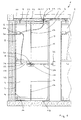
- Eine prinzipielle Ansicht einer mobilen Trennwand, die nicht abgedichtet und nicht verriegelt ist.
- Figur 2:
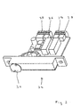
- Eine vergrößerte Ansicht einer Steuerungseinheit gemäß
Figur 1.
- Figure 1:
- A basic view of a mobile partition that is not sealed and not locked.
- Figure 2:
- An enlarged view of a control unit according to Figure 1.
Eine mobile Trennwand 1 ist aus mehreren tafelförmigen unabhängig
voneinander verfahrbaren Wandelementen 2 zusammengesetzt und zur
Raumunterteilung oder als Außenabschluss geeignet. Alle Wandelemente
2 können aus einer platzsparenden Parkposition, einem so genannten
Bahnhof, in die Trennwandachse gefahren und dort verspannt werden.A
Jedes dieser Wandelemente 2 besteht in dem Ausführungsbeispiel aus
einem verwindungssteifen Rahmen 3 aus Metall, insbesondere Stahl
und/oder Aluminium, und aus zwei im Abstand voneinander angeordneten
Deckplatten 4. Der Rahmen 3 jedes Wandelementes 2 weist an vertikalen
Seiten Längsträger 5 und an horizontalen Seiten Querträger 6 und 7 auf.
Des Weiteren ist mittig ein weiterer Querträger 8 zwischen den Langsträgern
5 befestigt. An dem oberen Querträger 6 sind zwei Laufwagen 9 und
10 angeordnet, mittels derer das Wandelement 2 in einer deckenseitig
befestigten Laufschiene 11 verfahrbar ist. An dem unteren Querträger 7
ist ein Zapfen 12 angeordnet, mittels dessen das Wandelement 2 in einer
nicht dargestellten Schiene bodenseitig geführt ist.Each of these
Zur horizontalen Abdichtung wird von den Querträgern 6, 7 jedes Wandelementes
2 jeweils ein Abschlussprofil 13 gegen die Laufschiene 11 und
jeweils ein Abschlussprofil 14 gegen den Boden gepresst, wobei im unbetätigten
Zustand die Abschlussprofile 13, 14 verdeckt in dem jeweiligen
Querträger 6, 7 angeordnet sind. Die Abschlussprofile 13, 14 sind mit
nicht dargestellten flexiblen Dichtstreifen versehen, die dazu bestimmt
sind, gegen die Laufschiene 11 bzw. Decke und den Boden angedrückt zu
werden. Beide Abschlussprofile 13, 14 sind mechanisch über eine an dem
mittigen Querträger 8 befestigte Gelenkschere 15 und verbindende Gestänge
16 mit dem jeweiligen Abschlussprofil 13, 14 gekoppelt. Die Gestänge
16 sind mit Rückstellorganen 17 in Form von Federn ausgestattet.For horizontal sealing of the
Des Weiteren ist an dem Querträger 8 ein Antrieb 18 befestigt, der die
Gelenkschere 15 motorisch antreibt. Der Antrieb 18 besteht vorzugsweise
aus einem als Gleichstrommotor ausgebildeten Elektromotor.Furthermore, a
Der Laufwagen 10 ist mit einem weiteren Antrieb 19 ausgebildet. Die Anbindung
des Laufwagens 10 erfolgt dabei über ein Hohlrohr 20, das in das
Wandelement 2 eingeschraubt ist. Der Antrieb 19 besteht vorzugsweise
aus einem als Gleichstrommotor ausgebildeten Elektromotor, der über
eine Wirkverbindung entlang der Laufschiene 11 verfahrbar ist. Der Laufwagen
10 ist des Weiteren mit Stromabnehmern 21 versehen, die elektrisch
leitend mit in der Laufschiene 11 ortsfest angeordneten Stromschienen
22 in Wirkverbindung steht. Die Stromabnehmer 21, vorzugsweise in
Form von Schleifkontakten, sind mit elektrischen Leitungen 23 verbunden,
die durch das Hohlrohr 20 in das Wandelement 2 geführt sind und die die
im Wandelement 2 angeordnete Steuerungseinheit 24 während des Verfahrens
des Wandelementes 2 mit der notwendigen elektrischen Energie
versorgen. Dabei streifen die Stromabnehmer 21 elektrisch leitend an oder
in den Stromschienen 22 entlang.The carriage 10 is formed with a
Die Steuerungseinheit 24 ist am Längsträger 5 des Wandelementes 2
befestigt und in Form einer bedruckten Platine realisiert, die einseitig bestückt
ist (Figur 2). Die Steuerungseinheit 24 weist verschiedene nicht näher
bezeichnete Bauteile auf, sowie Steckverbinder 25 bis 28 zum Anschluss
der Stromversorgung 23, der motorseitigen Steuerleitungen 29,
33 und verschiedener Positionsgeber 30, 31. Die Steckverbinder 25 bis 28
sind codiert ausgeführt, um Fehlsteckungen zu vermeiden, wobei die
Steckverbindung 25 mit der Leitung 23 verbunden ist, die sowohl die
Stromversorgung als auch die Steuerleitung 29 für den Antrieb 19 beinhaltet.
Über die Steckverbindung 26 und die zugehörige Leitung 33 wird
der Antrieb 18 angesteuert, während über die Steckverbindung 27 und die
zugehörige Leitung 34 der Positionsgeber 31 aktiviert wird.The
Die vorgenannten Positionsgeber 30, 31 sind als berührungslos arbeitende
Reed-Kontakte ausgeführt, die mit entsprechenden Magneten zusammenwirken.
An dem Längsträger 5 ist ein Positionsgeber 30 montiert, der
die horizontale Position des Wandelementes 2 detektiert. Dabei ist der
Positionsgeber 30 direkt in die Steuerungseinheit 24 integriert und wirkt
durch eine entsprechende Öffnung in dem Längsträger 5 mit dem korrespondierenden
Magneten eines stationären Wandabschlusses 32 oder eines
benachbarten Wandelementes 2 zusammen. Ein weiterer Positionsgeber
31 ist in der Gelenkschere 15 angeordnet, um die Positionierung
der Abschlussprofile 13, 14 zu detektieren.The
Nachfolgend wird die Funktionsweise der mobilen Trennwand 1 beschrieben.
Im unbetätigten Zustand befinden sich die einzelnen Wandelemente
2 der mobilen Trennwand 1 platzsparend in einem so genannten, nicht
dargestellten Bahnhof, der über eine Laufschienenanordnung mit der eigentlichen
Trennwandachse verbunden ist. Zum Aufbau der Trennwand 1
wird vorerst ein erstes Wandelement 2 über die Laufschiene 11 führend
gegen einen stationären Wandabschluss 32 zum Anliegen gebracht.The operation of the
Dabei wird die Steuerungseinheit 24 über die Stromabnehmer 21 mit elektrischer
Energie versorgt. Solange der Positionsgeber 30 geöffnet ist,
wird dem Antrieb 19 von der Steuerungseinheit 24 über die Leitung 23, 29
Strom zugeführt, so dass das Wandelement 2 gegen den stationären
Wandabschluss 32 fährt. Sobald der Positionsgeber 30 am Längsträger 5
geschlossen wird, schaltet die Steuerungseinheit 24 nach einer zeitlichen
Verzögerung den Strom auf den Antrieb 18 für die Verspannung der Abschlussprofile
13, 14 um. Die Zeitverzögerung wird benötigt, um einen
ausreichenden Anpressdruck gegenüber dem stationären Wandabschluss
32 aufzubauen. Sobald auch die Abschlussprofile 13, 14 über die Gelenkschere
15 vollständig verspannt sind, wird dieses Wandelement 2 von der
Steuerungseinheit 24 durch Überstromdetektion abgeschaltet. Beim Anfügen
weiterer Wandelemente 2 wiederholt sich der beschriebene Vorgang.The
Zum Entriegeln der Abschlussprofile 13, 14 wird in der Steuerungseinheit
24 eine Umpolung vorgenommen, so dass der Antrieb 18 in umgekehrter
Richtung läuft. Die Abschlussprofile 13, 14 fahren dabei in ihre Ausgangsposition
in den Querträgern 6, 7 zurück. Der Reed-Kontakt des in der Gelenkschere
15 angeordneten Positionsgebers 31 tritt dann mit dem Magneten
in Kontakt, so dass die Steuerungseinheit 24 den Antrieb 18 abschaltet
und den Antrieb 19 bestromt und das Wandelement 2 entlang der
Laufschiene 11 zurück in den Bahnhof gefahren wird.To unlock the end profiles 13, 14 is in the
Des Weiteren ist aus jeder Gelenkschere 15 eine Welle 35 nach außen
geführt, so dass im Falle eines Stromausfalles dort eine Kurbel 36 zur
manuellen Entspannung der Abschlussprofile 13, 14 eingesteckt werden
kann. Furthermore, a
Die vorstehende Beschreibung des Ausführungsbeispieles dient nur zu illustrativen Zwecken und nicht zum Zwecke der Beschränkung der Erfindung. Im Rahmen der Erfindung sind verschiedene Änderungen und Modifikationen möglich, ohne den Umfang der Erfindung sowie ihrer Äquivalente zu verlassen. The above description of the exemplary embodiment only serves illustrative purposes and not for the purpose of limiting the invention. Various changes and modifications are within the scope of the invention possible without the scope of the invention and its equivalents to leave.
- 11
- Trennwandpartition wall
- 22
- Wandelementwall element
- 33
- Rahmenframe
- 44
- Deckplattecover plate
- 55
- Längsträgerlongitudinal beams
- 66
- Querträgercrossbeam
- 77
- Querträgercrossbeam
- 88th
- Querträgercrossbeam
- 99
- Laufwagencarriage
- 1010
- Laufwagencarriage
- 1111
- Laufschienerunner
- 1212
- Zapfenspigot
- 1313
- AbschlussprofilEnd profile
- 1414
- AbschlussprofilEnd profile
- 1515
- Gelenkschereswivel joint
- 1616
- Gestängelinkage
- 1717
- RückstellorganRestoring member
- 1818
- Antriebdrive
- 1919
- Antriebdrive
- 2020
- Hohlrohrhollow tube
- 2121
- Stromabnehmerpantograph
- 2222
- Stromschieneconductor rail
- 2323
- Leitungmanagement
- 2424
- Steuerungseinheitcontrol unit
- 2525
- SteckverbinderConnectors
- 2626
- SteckverbinderConnectors
- 2727
- SteckverbinderConnectors
- 2828
- Steckverbinder Connectors
- 2929
- Leitungmanagement
- 3030
- Positionsgeberlocator
- 3131
- Positionsgeberlocator
- 3232
- Wandabschlusswall end
- 3333
- Leitungmanagement
- 3434
- Leitungmanagement
- 3535
- Wellewave
- 3636
- Kurbelcrank
Claims (14)
Applications Claiming Priority (2)
| Application Number | Priority Date | Filing Date | Title |
|---|---|---|---|
| DE10300821 | 2003-01-10 | ||
| DE10300821A DE10300821A1 (en) | 2003-01-10 | 2003-01-10 | Mobile partition |
Publications (1)
| Publication Number | Publication Date |
|---|---|
| EP1437468A1 true EP1437468A1 (en) | 2004-07-14 |
Family
ID=32478208
Family Applications (1)
| Application Number | Title | Priority Date | Filing Date |
|---|---|---|---|
| EP04000304A Withdrawn EP1437468A1 (en) | 2003-01-10 | 2004-01-09 | Movable partition wall |
Country Status (2)
| Country | Link |
|---|---|
| EP (1) | EP1437468A1 (en) |
| DE (1) | DE10300821A1 (en) |
Cited By (4)
| Publication number | Priority date | Publication date | Assignee | Title |
|---|---|---|---|---|
| WO2010025879A1 (en) * | 2008-09-03 | 2010-03-11 | Dorma Gmbh & Co. Kg | Mobile partition |
| EP2385182A3 (en) * | 2010-05-03 | 2015-01-07 | Dorma GmbH + Co. KG | Mobile partition with telescopic unit |
| EP3260618A1 (en) * | 2016-06-22 | 2017-12-27 | Wheel.me AS | Movable wall element and movable wall system |
| WO2024020609A1 (en) * | 2022-07-25 | 2024-02-01 | Peneder Bau-Elemente GmbH | Door system |
Families Citing this family (1)
| Publication number | Priority date | Publication date | Assignee | Title |
|---|---|---|---|---|
| DE102015108660A1 (en) * | 2015-06-01 | 2016-12-01 | Dorma Deutschland Gmbh | Partition module of a partition |
Citations (6)
| Publication number | Priority date | Publication date | Assignee | Title |
|---|---|---|---|---|
| DE3147273A1 (en) * | 1981-11-28 | 1983-07-28 | Justin Hüppe GmbH, 2900 Oldenburg | Room partition wall |
| DE9209496U1 (en) * | 1992-07-15 | 1993-11-18 | Hueppe Form Sonnenschutz | Control device for controlling a drive device of a room partition |
| EP0806537A1 (en) * | 1995-09-26 | 1997-11-12 | Faiveley Espanola, S.A. | System for determining the position in automatic doors |
| DE19648435A1 (en) * | 1996-11-22 | 1998-05-28 | Steinel Ag | Door operator |
| DE19831806A1 (en) * | 1997-07-15 | 1999-01-28 | Geze Gmbh | Automatic sliding electric door or window |
| US6233878B1 (en) * | 1998-04-27 | 2001-05-22 | Kaba Gilgen Ag | Sliding wall |
Family Cites Families (1)
| Publication number | Priority date | Publication date | Assignee | Title |
|---|---|---|---|---|
| DE29922545U1 (en) * | 1999-12-24 | 2000-04-27 | Grafenhorst Heinrich | Automatic monorail conveyor system, especially wall element conveyor system |
-
2003
- 2003-01-10 DE DE10300821A patent/DE10300821A1/en not_active Ceased
-
2004
- 2004-01-09 EP EP04000304A patent/EP1437468A1/en not_active Withdrawn
Patent Citations (6)
| Publication number | Priority date | Publication date | Assignee | Title |
|---|---|---|---|---|
| DE3147273A1 (en) * | 1981-11-28 | 1983-07-28 | Justin Hüppe GmbH, 2900 Oldenburg | Room partition wall |
| DE9209496U1 (en) * | 1992-07-15 | 1993-11-18 | Hueppe Form Sonnenschutz | Control device for controlling a drive device of a room partition |
| EP0806537A1 (en) * | 1995-09-26 | 1997-11-12 | Faiveley Espanola, S.A. | System for determining the position in automatic doors |
| DE19648435A1 (en) * | 1996-11-22 | 1998-05-28 | Steinel Ag | Door operator |
| DE19831806A1 (en) * | 1997-07-15 | 1999-01-28 | Geze Gmbh | Automatic sliding electric door or window |
| US6233878B1 (en) * | 1998-04-27 | 2001-05-22 | Kaba Gilgen Ag | Sliding wall |
Cited By (10)
| Publication number | Priority date | Publication date | Assignee | Title |
|---|---|---|---|---|
| WO2010025879A1 (en) * | 2008-09-03 | 2010-03-11 | Dorma Gmbh & Co. Kg | Mobile partition |
| CN102144067B (en) * | 2008-09-03 | 2013-03-13 | 多玛两合有限公司 | Mobile partition |
| EP2385182A3 (en) * | 2010-05-03 | 2015-01-07 | Dorma GmbH + Co. KG | Mobile partition with telescopic unit |
| EP3260618A1 (en) * | 2016-06-22 | 2017-12-27 | Wheel.me AS | Movable wall element and movable wall system |
| WO2017220628A1 (en) * | 2016-06-22 | 2017-12-28 | Wheel.Me As | Movable wall element and movable wall system |
| CN109642426A (en) * | 2016-06-22 | 2019-04-16 | 威欧.艾姆伊有限公司 | Displaceable wall element and displaceable wall system |
| RU2732903C2 (en) * | 2016-06-22 | 2020-09-24 | Вил.Ми Ас | Movable wall element and movable wall system |
| US11015342B2 (en) | 2016-06-22 | 2021-05-25 | Wheel.Me As | Movable wall element and movable wall system |
| CN109642426B (en) * | 2016-06-22 | 2021-07-16 | 威欧·艾姆伊有限公司 | Movable wall element and movable wall system |
| WO2024020609A1 (en) * | 2022-07-25 | 2024-02-01 | Peneder Bau-Elemente GmbH | Door system |
Also Published As
| Publication number | Publication date |
|---|---|
| DE10300821A1 (en) | 2004-07-29 |
Similar Documents
| Publication | Publication Date | Title |
|---|---|---|
| EP0953706B2 (en) | Stackable sliding wall | |
| DE102008028831B4 (en) | Drive system for driving and guiding a wall element for a room dividing wall system | |
| DE19831765B4 (en) | Automatic door or window system | |
| WO1997042388A1 (en) | Sliding wall | |
| WO2015018888A1 (en) | Contact device and charging contact unit and method for electrical connection of a vehicle to a charging station | |
| EP1552096B1 (en) | Device for displaceable divider elements, running gear and divider element | |
| EP1681420A1 (en) | Wing assembly with a sliding wing and a fixed wing | |
| EP1801339A2 (en) | Drive for actuating a movable wing, particularly for a door or a window | |
| EP0597208B1 (en) | Partition wall with a plurality of wall panels | |
| WO2005090116A1 (en) | Magnet arrangement for a magnetic levitation vehicle | |
| EP1129269B1 (en) | Automatic door or window system | |
| WO2005090115A1 (en) | Magnet arrangement for a magnetic levitation vehicle | |
| WO1996002724A1 (en) | Device and method of operating an automatic partition system | |
| DE102007060375A1 (en) | Rail-mounted mobile wall element has wall body and roll car is connected with wall body, where roll car is arranged to move in guiding rail | |
| DE102005032168A1 (en) | Circular sliding doors for entry and exit, include individually-controlled doors operated by linear drives in diverse modes ranging from airlock to escape | |
| DE102020101923A1 (en) | Charging system for an at least partially electrically powered vehicle | |
| EP1437468A1 (en) | Movable partition wall | |
| EP1647514B1 (en) | Inclined elevator | |
| EP2331762B1 (en) | Sliding partition | |
| EP1094186A1 (en) | Rail with current supply device | |
| EP1441089A1 (en) | Device for inspection and/or maintenance and/or servicing of rail vehicles superstructures | |
| EP0348444B1 (en) | Parking system | |
| EP0413659B2 (en) | Installation having movable motorised rail guided units | |
| CH651349A5 (en) | Drive apparatus, in particular for parking slabs | |
| EP4219221A1 (en) | Charging system |
Legal Events
| Date | Code | Title | Description |
|---|---|---|---|
| PUAI | Public reference made under article 153(3) epc to a published international application that has entered the european phase |
Free format text: ORIGINAL CODE: 0009012 |
|
| AK | Designated contracting states |
Kind code of ref document: A1 Designated state(s): AT BE BG CH CY CZ DE DK EE ES FI FR GB GR HU IE IT LI LU MC NL PT RO SE SI SK TR |
|
| AX | Request for extension of the european patent |
Extension state: AL LT LV MK |
|
| 17P | Request for examination filed |
Effective date: 20050114 |
|
| AKX | Designation fees paid |
Designated state(s): AT BE BG CH CY CZ DE DK EE ES FI FR GB GR HU IE IT LI LU MC NL PT RO SE SI SK TR |
|
| 17Q | First examination report despatched |
Effective date: 20050321 |
|
| STAA | Information on the status of an ep patent application or granted ep patent |
Free format text: STATUS: THE APPLICATION IS DEEMED TO BE WITHDRAWN |
|
| 18D | Application deemed to be withdrawn |
Effective date: 20060602 |