EP1437320A1 - Elevator device and car movement limiting device thereof - Google Patents
Elevator device and car movement limiting device thereof Download PDFInfo
- Publication number
- EP1437320A1 EP1437320A1 EP01934433A EP01934433A EP1437320A1 EP 1437320 A1 EP1437320 A1 EP 1437320A1 EP 01934433 A EP01934433 A EP 01934433A EP 01934433 A EP01934433 A EP 01934433A EP 1437320 A1 EP1437320 A1 EP 1437320A1
- Authority
- EP
- European Patent Office
- Prior art keywords
- car
- movable member
- switch
- elevator apparatus
- accommodating
- Prior art date
- Legal status (The legal status is an assumption and is not a legal conclusion. Google has not performed a legal analysis and makes no representation as to the accuracy of the status listed.)
- Granted
Links
Images


Classifications
-
- B—PERFORMING OPERATIONS; TRANSPORTING
- B66—HOISTING; LIFTING; HAULING
- B66B—ELEVATORS; ESCALATORS OR MOVING WALKWAYS
- B66B5/00—Applications of checking, fault-correcting, or safety devices in elevators
- B66B5/0043—Devices enhancing safety during maintenance
- B66B5/005—Safety of maintenance personnel
-
- B—PERFORMING OPERATIONS; TRANSPORTING
- B66—HOISTING; LIFTING; HAULING
- B66B—ELEVATORS; ESCALATORS OR MOVING WALKWAYS
- B66B5/00—Applications of checking, fault-correcting, or safety devices in elevators
-
- B—PERFORMING OPERATIONS; TRANSPORTING
- B66—HOISTING; LIFTING; HAULING
- B66B—ELEVATORS; ESCALATORS OR MOVING WALKWAYS
- B66B17/00—Hoistway equipment
- B66B17/34—Safe lift clips; Keps
Definitions
- This invention relates to an elevator apparatus in which the operation mode is switched to an on-car maintenance operation mode at the time of maintenance operation on the car and to a car movement regulating device used in the elevator apparatus and adapted to mechanically regulate the car movement during maintenance operation on the car.
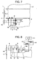
- Fig. 7 is a plan view showing the car movement regulating device of a conventional elevator apparatus disclosed, for example, in JP 2000-203774 A
- Fig. 8 is a front view showing the car movement regulating device of Fig. 7.
- a hoistway 1 in a hoistway 1, there are installed a pair of guide rails 3 for guiding the ascent and descent of a car 2.
- Fixed to each guide rail 3 is a stationary plate 4 having an engagement hole 4a.
- a bracket 6 is mounted to an upper beam 5 of the car 2.
- a lock bar 7 is supported by the bracket 6.
- the lock bar 7 is linearly reciprocated through manual operation between an engagement position (indicated by the broken line in the drawing) where its forward end portion is inserted into the engagement hole 4a and an accommodating position (indicated by the solid line in the drawing) where it is retracted to a position on the car 2.
- An operating lever 8 for manually operating the lock bar 7 is mounted to the lock bar 7.
- a retaining plate 9 for retaining the lock bar 7 at the engagement position and the accommodating position.
- first and second grooves 9a and 9b are provided in the retaining plate 9 into which the operating lever 8 is inserted, respectively when the lock bar 7 is at the engagement position and at the accommodating position.
- a limit switch 10 mounted to the bracket 6 is a limit switch 10 to be closed when the lock bar 7 is at the accommodating position.
- An operating portion 10a of the limit switch 10 is operated by the rear end portion of the lock bar 7.
- a hoist 11 for raising and lowering the car 2 is controlled by a control unit 12.
- a control unit 12 there is provided a power circuit 13 for supplying power to the hoist 11.
- the limit switch 10 is connected to the power circuit 13. When the limit switch 10 is closed, the power circuit 13 is in the ON state, and when the limit switch 10 is open, the power circuit 13 is in the OFF state.
- the limit switch 10 only detects whether the lock bar 7 is at the accommodating position or not; it is impossible for it to detect whether the lock bar 7 has been appropriately moved to the engagement position, that is, whether the forward end portion of the lock bar 7 has been surely inserted into the engagement hole 4a. Further, it is impossible to detect that the forward end portion of the lock bar 7 is somewhere between the accommodating position and the engagement position. Thus, when the lock bar 7 is not at the accommodating position, it is only possible to perform a simple control to prevent the hoist 11 from being driven.
- the hoist 11 can be driven with the lock bar 7 somewhere between the two positions, so that the lock bar 7 may interfere with an apparatus in the hoistway 1, thereby damaging the apparatus.
- This invention has been made with a view toward solving the above problems in the prior art. It is an object of this invention to provide an elevator apparatus in which it is possible to perform finer control according to the position of a movable member for regulating the movement of the car to thereby achieve an improvement in operability in the maintenance operation on the car and a car movement regulating device thereof.
- a car movement regulating device for an elevator apparatus which is used in an elevator apparatus equipped with a car ascending and descending in a hoistway, a driving device for raising and lowering the car, and a control device for controlling the driving device and which serves to mechanically regulate movement of the car during maintenance operation on the car
- the device including: a stationary member fixed to one of the interior of the hoistway and the car and having a stationary side engagement portion; a movable member which has a movable side engagement portion to be engaged with the stationary side engagement portion, which is provided in the other of the interior of the hoistway and the car, and which can be displaced between an accommodating position and an engagement position where the movable side engagement portion is engaged with the stationary side engagement portion; and a switch device connected to the control device and adapted to distinguish and detect which of the three positions: the accommodating position, the engagement position, and a halfway position between the accommodating position and the engagement position the movable member is placed at.
- an elevator apparatus includes: a car ascending and descending in a hoistway; a driving device for raising and lowering the car; a stationary member fixed to one of the interior of the hoistway and the car and having a stationary side engagement portion; a movable member which has a movable side engagement portion to be engaged with the stationary side engagement portion, which is provided in the other of the interior of the hoistway and the car, and which can be displaced between an accommodating position and an engagement position where the movable side engagement portion is engaged with the stationary side engagement portion; a switch device for distinguishing and detecting which of the three positions: the accommodating position, the engagement position, and a halfway position between the accommodating position and the engagement position the movable member is placed at; and a control device which controls the driving device by selectively switching between a plurality of operation modes including a normal mode and an on-car maintenance mode and to which a signal from the switch device is input, wherein when the operation mode is the on-car maintenance mode, the control device allows operation of the
- Fig. 1 is a schematic diagram showing the car movement regulating device for an elevator apparatus according to an embodiment of this invention.
- an engagement plate 21 serving as a stationary member is fixed to a stationary portion in the hoistway, e.g., a guide rail.
- an engagement hole 21a serving as a stationary side engagement portion is provided in the engagement plate 21, there is provided an engagement hole 21a serving as a stationary side engagement portion.
- An arm 23 serving as a movable member is mounted on a car 22 that is raised and lowered in the hoistway.
- the arm 23 is rotatable about an axle 24 between an accommodating position (Fig. 1) and an engagement position (Figs. 3 and 4).
- a hook portion 23a serving as a movable side engagement portion to be engaged with the peripheral edge portion of the engagement hole 21a.
- a cam 25 is fixed to the arm 23.
- the first switch 26 is mounted on the car 22 a first switch 26 operated by the cam 25.
- the first switch 26 has a normally-closed contact 26a, and is closed when the arm 23 is at the accommodating position; when the arm 23 is at a halfway position between the accommodating position and the engagement position (Fig. 2) or the engagement position, it is operated to be opened by the cam 25.
- the first switch 26 is mechanically operated by the arm 23 and is forcibly closed.
- the second switch 27 is mounted on the arm 23 a second switch 27 operated by the engagement plate 21.
- the second switch 27 has a normally-open contact 27a, and is open when the arm 23 is at the accommodating position or the halfway position; when the arm 23 is at the engagement position, it is closed.
- a switch device 28 has first and second switches 26 and 27, and is adapted to detect which of the three positions: the accommodating position, the engagement position, and the halfway position the arm 23 is placed at.
- the car 22 is raised and lowered by the drive force of a driving device 29.
- the driving device 29 is controlled by a control device 30.
- the control device 30 controls the driving device 29 by selectively switching between a plurality of operation modes including a normal mode and an on-car maintenance mode.
- the first switch 26 is connected in series to a safety circuit (not shown), so that when the normally-closed contact 26a is opened, supply of electricity to the driving device 29 is cut off.
- a safety circuit not shown
- bypass switch for opening and closing a bypass circuit for short-circuiting (bypassing) the first switch 26 along with an on-car operating switch for operating the car 22.
- the movement of the car 22 is mechanically regulated within the range of the engagement hole 21a.
- the brake device is released with the balance weight (not shown) being heavier than the car 22, the car 22 ascends; however, as shown in Fig. 4, the hook portion 23a engages with the upper edge portion of the engagement hole 21a, whereby the ascent of the car 22 is regulated.
- the operation mode is first switched to the on-car maintenance operation mode, and the car 22 is moved at low speed to a predetermined maintenance position. Thereafter, the arm 23 is rotated to the engagement position, and the hook portion 23a is engaged with the engagement hole 21a of the stationary plate 21, whereby the movement of the car 22 is regulated, and maintenance operation is performed on the car 22.
- the arm 23 After the completion of the maintenance operation, the arm 23 is restored to the accommodating position, and the operation mode is restored to the normal operation mode.
- the hook 23a is in contact with the peripheral edge portion of the engagement hole 21a
- the bypass switch and the on-car operating switch are simultaneously operated to slightly raise or lower the car 22 to restore the position of the hook portion 23a with respect to the engagement hole 21a to the position of Fig. 3, and then the arm 23 is rotated to the accommodating position.
- Fig. 5 is a flowchart illustrating the operation of the control device 30 of Fig. 1 in the normal operation mode.
- the normal operation mode it is first checked whether the arm 23 is at the accommodating position (step S1). Then, when the arm 23 is not at the accommodating position, the operation of the car 22 is prohibited (step S2), whereby interference of the arm 23 with the ascent/descent apparatus is more reliably prevented.
- step S3 When it is confirmed that the arm 23 is at the accommodating position, a judgment is made as to whether the arm 23 is at the engagement position (step S3). Normally, when the arm 23 is at the accommodating position, the second switch 27 is open, so that it is confirmed that the arm 23 is not at the engagement position, making it possible to operate the car 22 (step S4).
- step S5 when it is detected that the arm 23 is at the engagement position although it has been detected that the arm 23 is at the accommodating position, it is determined that failure has occurred in the switch device 28, and an error detection signal is output (step S5).
- both the first and second switches 26 and 27 are closed even if the arm 23 is at the accommodating position. In such a case, an error detection signal is output, and the switch device 28 is repaired or replaced by the operator.
- Fig. 6 is a flowchart illustrating the operation of the control device 30 of Fig. 1 in the on-car maintenance operation mode.
- the on-car maintenance operation mode it is first checked whether the arm 23 is at the accommodating position (step S1). When it is confirmed that the arm 23 is at the accommodating position, a judgment is made as to whether the arm 23 is at the engagement position (step S3).
- step S4 When it is confirmed that the arm 23 is not at the engagement position, it is determined that the arm 23 is at the accommodating position and that there is no abnormality in the switch 28, making it possible to operate the car 22 (step S4). Thus, even in the on-car maintenance operation mode, when the arm 23 is at the accommodating position, it is possible to operate the car 22, and the can 22 can be moved to a predetermined maintenance position.
- step S5 When it is detected that the arm 23 is at both the accommodating position and the engagement position, it is determined that the switch device 28 is out of order, and an error detection signal is output (step S5).
- step S6 a judgment is made as to whether the arm 23 is at the engagement position.
- step S7 it is determined that the arm 23 is at the halfway position, and the operation of the car 22 is prohibited.
- the operation of the car 22 is prohibited while the arm 23 is being operated and in the state in which the arm 23 is not appropriately engaged with the engagement plate 21.
- the car 22 is not raised or lowered.
- step S8 When it is detected that the arm 23 is not at the accommodating position but at the engagement position, the operation of the car 22 is prohibited, and a release command signal for the brake device of the driving device 29 is made ready to be output (step S8), whereby the brake device can be released, and maintenance operation can be conducted with the brake device released. Further, as described above, when the bypass switch and the on-car operation switch are simultaneously operated, the car 22 can be operated at low speed.
- this car movement regulating device for an elevator apparatus it is possible to detect by means of the switch device 28 which of the three positions: the accommodating position, the engagement position, and the halfway position, the arm 23 is placed at, so that it is possible to conduct finer control according to the position of the arm 23, whereby it is possible to achieve an improvement in the operability of maintenance operations on the car.
- the switch device 28 which has the first switch 26, which is closed when the arm 23 is at the accommodating position and opened when the arm 23 is at the halfway position or the engagement position, and the second switch 27, which is opened when the arm 23 is at the accommodating position or the halfway position and closed when the arm 23 is at the engagement position, is used, so that it is possible to distinguish and detect the accommodating position, the engagement position, and the halfway position with a simple construction.
- the first switch 26 is arranged such that when the arm 23 is restored to the accommodating position, it is operated by the arm 23 to be forcibly closed, so that even when the first switch 26 does not spontaneously return to its original position, it is possible to operate the first switch 26 in the normal fashion.
- the arm 23 is equippedwith the cam 25 that operates the f irst switch 2 6 when it is at the halfway position or the engagement position, so that the first switch 26 can be operated more reliably.
- the control device 30 enables the car 22 to be operated when it is detected that the arm 23 is at the accommodating position; when it is detected that the arm 23 is at the halfway position or the engagement position, it prohibits the operation of the car 22, so that it is possible to perform the maintenance operation on the car 22 more safely.
- the control device 30 prohibits the operation of the car 22 when it is detected that the arm 23 is not at the accommodating position, so that it is possible to more reliably prevent interference of the arm 23 with the ascent/descent apparatus.
- a release command signal for the brake device is output only when it is detected that the arm 23 is at the engagement position, so that it is possible to release the brake device more safely.
- closing the bypass circuit through operation of the bypass switch makes it possible to operate the car 22 through operation of the on-car operating switch, so that it is possible to raise or lower the car 22 even when the arm 23 is at the engagement position, making it possible to easily cancel the engaged state of the arm 23.
- the engagement plate 21 is fixed in the hoistway and the arm 23 is mounted on the car 22, it is also possible to fix a stationary member to the car and to provide a movable member in the hoistway.
- the movable member consists of a rotatable arm 23, it is also possible to use a slidable movable member as shown in Figs. 7 and 8.
Landscapes
- Maintenance And Inspection Apparatuses For Elevators (AREA)
- Elevator Control (AREA)
Abstract
Description
Claims (12)
- A car movement regulating device for an elevator apparatus which is used in an elevator apparatus equipped with a car ascending and descending in a hoistway, a driving device for raising and lowering the car, and a control device for controlling the driving device and which serves to mechanically regulate movement of the car during maintenance operations on the car, the device comprising:a stationary member fixed to one of the interior of the hoistway and the car and having a stationary side engagement portion;a movable member which has a movable side engagement portion to be engaged with the stationary side engagement portion, which is provided in the other of the interior of the hoistway and the car, and which can be displaced between an accommodating position and an engagement position where the movable side engagement portion is engaged with the stationary side engagement portion; anda switch device connected to the control device and adapted to distinguish and detect which of the three positions: the accommodating position, the engagement position, and a halfway position between the accommodating position and the engagement position the movable member is placed at.
- A car movement regulating device for an elevator apparatus according to Claim 1, wherein the switch device has a first switch which is closed when the movable member is at the accommodating position and opened when the movable member is at the halfway position or the engagement position and a second switch which is opened when the movable member is at the accommodating position or the halfway position and closed when the movable member is at the engagement position.
- A car movement regulating device for an elevator apparatus according to Claim 2, wherein the first switch is arranged such that by restoring the movable member to the accommodating position, it is operated by the movable member to be forcibly closed.
- A car movement regulating device for an elevator apparatus according to Claim 2, wherein the movable member is rotated to be displaced between the accommodating position and the engagement position about an axle.
- A car movement regulating device for an elevator apparatus according to Claim 4, wherein the movable member is equipped with a cam for operating the first switch when it is at the halfway position or the engagement position.
- A car movement regulating device for an elevator apparatus according to Claim 2, wherein the stationary member is fixed in the interior of the hoistway, and wherein the movable member is mounted on the car, with the first switch being mounted on the car and the second switch being mounted on the movable member.
- An elevator apparatus comprising:wherein when the operation mode is the on-car maintenance mode, the control device allows operation of the car when it is detected that the movable member is at the accommodating position, and prohibits operation of the car when it is detected that the movable member is at the halfway position.a car that is raised and lowered in a hoistway;a driving device for raising and lowering the car;a stationary member fixed to one of the interior of the hoistway and the car and having a stationary side engagement portion;a movable member which has a movable side engagement portion to be engaged with the stationary side engagement portion, which is provided in the other of the interior of the hoistway and the car, and which can be displaced between an accommodating position and an engagement position where the movable side engagement portion is engaged with the stationary side engagement portion;a switch device for distinguishing and detecting which of the three positions: the accommodating position, the engagement position, and a halfway position between the accommodating position and the engagement position the movable member is placed at; anda control device which controls the driving device by selectively switching between a plurality of operation modes including a normal mode and an on-car maintenance mode and to which a signal from the switch device is input,
- An elevator apparatus according to Claim 7, wherein when the operation mode is the normal mode, the control device prohibits operation of the car when it is detected that the movable member is not at the accommodating position.
- An elevator apparatus according to Claim 7, wherein the driving device is equipped with a brake device, and wherein the control device makes it possible to output a release command signal for the brake device only when the operation mode is the on-car maintenance mode and it is detected that the movable member is at the engagement position.
- An elevator apparatus according to Claim 7, wherein the switch device has a first switch which is closed when the movable member is at the accommodating position and opened when the movable member is at the halfway position or the engagement position and a second switch which is opened when the movable member is at the accommodating position or the halfway position and closed when the movable member is at the engagement position.
- An elevator apparatus according to Claim 10, wherein when both the first and second switches are closed, the control device generates an error detection signal for the switch device.
- An elevator apparatus according to Claim 10, wherein provided on the car are an on-car operating switch for operating the car and a bypass switch for opening and closing a bypass circuit for short-circuiting the first switch, and wherein when the movable member is at the engagement position, the control device makes it possible to operate the car through operation of the on-car operating switch when the bypass circuit is closed through operation of the bypass switch.
Applications Claiming Priority (1)
| Application Number | Priority Date | Filing Date | Title |
|---|---|---|---|
| PCT/JP2001/004566 WO2002098780A1 (en) | 2001-05-30 | 2001-05-30 | Elevator device and car movement limiting device thereof |
Publications (3)
| Publication Number | Publication Date |
|---|---|
| EP1437320A1 true EP1437320A1 (en) | 2004-07-14 |
| EP1437320A4 EP1437320A4 (en) | 2005-06-22 |
| EP1437320B1 EP1437320B1 (en) | 2007-01-10 |
Family
ID=11737374
Family Applications (1)
| Application Number | Title | Priority Date | Filing Date |
|---|---|---|---|
| EP01934433A Expired - Lifetime EP1437320B1 (en) | 2001-05-30 | 2001-05-30 | Elevator device and car movement limiting device thereof |
Country Status (6)
| Country | Link |
|---|---|
| EP (1) | EP1437320B1 (en) |
| JP (1) | JP4896370B2 (en) |
| KR (1) | KR100506476B1 (en) |
| CN (1) | CN1184127C (en) |
| DE (1) | DE60125990T2 (en) |
| WO (1) | WO2002098780A1 (en) |
Cited By (4)
| Publication number | Priority date | Publication date | Assignee | Title |
|---|---|---|---|---|
| WO2007046742A1 (en) * | 2005-10-21 | 2007-04-26 | Alimak Ab | Safety arrangement for a lift car in a lift |
| EP2301881A1 (en) * | 2009-09-29 | 2011-03-30 | Aufzugswerke M. Schmitt & Sohn GmbH & Co. | Lift assembly with locking device |
| LU92027B1 (en) * | 2012-06-21 | 2013-12-23 | Khalil Mahmoud Abu Al-Rubb | Lift safety mechanism |
| EP3012217B1 (en) | 2014-10-21 | 2017-05-17 | Kone Corporation | Safety system for elevator |
Families Citing this family (16)
| Publication number | Priority date | Publication date | Assignee | Title |
|---|---|---|---|---|
| JP5429808B2 (en) * | 2010-01-29 | 2014-02-26 | 東芝エレベータ株式会社 | Elevator hoisting machine brake |
| CN101891091B (en) * | 2010-07-08 | 2012-01-25 | 湖南海诺电梯有限公司 | Mechanical holdout device under lift well |
| CN103079980B (en) * | 2010-09-06 | 2015-06-10 | 株式会社日立制作所 | Elevator device |
| JP5421232B2 (en) * | 2010-12-08 | 2014-02-19 | 株式会社日立製作所 | Elevator equipment |
| JP2016098106A (en) * | 2014-11-26 | 2016-05-30 | 三菱電機株式会社 | Car fixation device for elevator |
| CN105236231B (en) * | 2015-11-03 | 2018-10-26 | 陈帅 | Elevator protection mechanism |
| CN108473276B (en) * | 2016-01-08 | 2019-10-11 | 三菱电机株式会社 | Car movement restriction device and elevator |
| CN105858389B (en) * | 2016-05-24 | 2018-03-20 | 广州广日电梯工业有限公司 | Elevator weighing stroke amplification device and the elevator with the device |
| CN109562907B (en) * | 2016-08-01 | 2023-09-26 | 三菱电机株式会社 | Elevator car fixing device |
| JP6251368B1 (en) * | 2016-12-07 | 2017-12-20 | 東芝エレベータ株式会社 | Elevator maintenance work support system |
| WO2019064451A1 (en) * | 2017-09-28 | 2019-04-04 | 三菱電機株式会社 | Elevator car constraining apparatus |
| CN111566036B (en) * | 2018-01-26 | 2021-11-09 | 三菱电机大楼技术服务株式会社 | Control device having function of maintaining position of elevator car at position suitable for operation, and elevator system |
| JP6521183B1 (en) * | 2018-01-26 | 2019-05-29 | 三菱電機ビルテクノサービス株式会社 | Control device and elevator system having a function to ensure the safety of elevator workers |
| CN111071901A (en) * | 2018-10-19 | 2020-04-28 | 奥的斯电梯公司 | Elevator system and multi-deck car for elevator system |
| JP7608899B2 (en) * | 2021-03-17 | 2025-01-07 | 三菱電機株式会社 | Elevator cage movement restriction device |
| GB2637059B (en) * | 2024-09-17 | 2026-04-15 | Advanced Handling Ltd | A support device for a lift system |
Family Cites Families (6)
| Publication number | Priority date | Publication date | Assignee | Title |
|---|---|---|---|---|
| JPS585914A (en) * | 1981-07-02 | 1983-01-13 | 鈴木 良典 | Switch with two contacts |
| JPS62161153U (en) * | 1986-04-01 | 1987-10-13 | ||
| JPH0356378A (en) * | 1989-07-25 | 1991-03-11 | Toshiba Corp | Elevator inspecting device |
| JP2596906Y2 (en) * | 1993-01-19 | 1999-06-28 | 株式会社タダノ | Work vehicle safety devices |
| JP2000203774A (en) * | 1998-11-12 | 2000-07-25 | Toshiba Corp | Stop lock device for elevator cage |
| JP2001019295A (en) * | 1999-07-08 | 2001-01-23 | Hitachi Building Systems Co Ltd | Operation state holding jig for limit switch operating device |
-
2001
- 2001-05-30 CN CNB018134629A patent/CN1184127C/en not_active Expired - Lifetime
- 2001-05-30 JP JP2003501782A patent/JP4896370B2/en not_active Expired - Fee Related
- 2001-05-30 WO PCT/JP2001/004566 patent/WO2002098780A1/en not_active Ceased
- 2001-05-30 DE DE60125990T patent/DE60125990T2/en not_active Expired - Lifetime
- 2001-05-30 KR KR10-2003-7000920A patent/KR100506476B1/en not_active Expired - Fee Related
- 2001-05-30 EP EP01934433A patent/EP1437320B1/en not_active Expired - Lifetime
Cited By (9)
| Publication number | Priority date | Publication date | Assignee | Title |
|---|---|---|---|---|
| WO2007046742A1 (en) * | 2005-10-21 | 2007-04-26 | Alimak Ab | Safety arrangement for a lift car in a lift |
| AU2006302758B2 (en) * | 2005-10-21 | 2011-11-03 | Alimak Ab | Safety arrangement for a lift car in a lift |
| EP1940716A4 (en) * | 2005-10-21 | 2013-03-20 | Alimak Ab | SAFETY ARRANGEMENT FOR AN ELEVATOR CABIN IN AN ELEVATOR |
| US8875845B2 (en) | 2005-10-21 | 2014-11-04 | Alimak Ab | Safety arrangement for a lift car in a lift |
| EP2301881A1 (en) * | 2009-09-29 | 2011-03-30 | Aufzugswerke M. Schmitt & Sohn GmbH & Co. | Lift assembly with locking device |
| LU92027B1 (en) * | 2012-06-21 | 2013-12-23 | Khalil Mahmoud Abu Al-Rubb | Lift safety mechanism |
| WO2013189993A1 (en) * | 2012-06-21 | 2013-12-27 | WATTERSON, Peer Marten John | Lift safety mechanism |
| US9556003B2 (en) | 2012-06-21 | 2017-01-31 | Khalil Mahmoud ABU AL-RUBB | Lift safety mechanism |
| EP3012217B1 (en) | 2014-10-21 | 2017-05-17 | Kone Corporation | Safety system for elevator |
Also Published As
| Publication number | Publication date |
|---|---|
| EP1437320A4 (en) | 2005-06-22 |
| DE60125990T2 (en) | 2007-10-25 |
| KR100506476B1 (en) | 2005-08-03 |
| DE60125990D1 (en) | 2007-02-22 |
| CN1444539A (en) | 2003-09-24 |
| CN1184127C (en) | 2005-01-12 |
| KR20030018058A (en) | 2003-03-04 |
| JP4896370B2 (en) | 2012-03-14 |
| EP1437320B1 (en) | 2007-01-10 |
| JPWO2002098780A1 (en) | 2004-09-16 |
| WO2002098780A1 (en) | 2002-12-12 |
Similar Documents
| Publication | Publication Date | Title |
|---|---|---|
| EP1437320B1 (en) | Elevator device and car movement limiting device thereof | |
| EP1864935B1 (en) | Elevator apparatus | |
| JP5452726B2 (en) | Elevator operation mode switching system | |
| EP3322660B1 (en) | Elevator control system | |
| JP5312571B2 (en) | Elevator equipment | |
| EP2163502A1 (en) | Elevator | |
| CN103204419B (en) | Electronic safe elevator | |
| WO2005115900A1 (en) | Elevator system | |
| EP2763925B1 (en) | Elevator brake control | |
| WO2006103769A1 (en) | Elevator apparatus | |
| KR101202511B1 (en) | Elevator control device | |
| EP1739045A1 (en) | Actuator driving method and actuator driving circuit | |
| CN103889873A (en) | Elevator with operation switching system | |
| JPH0859119A (en) | Operation device for elevator maintenance provided at landing | |
| KR100745908B1 (en) | Emergency stop of elevator | |
| JP3591419B2 (en) | Elevator safety equipment | |
| KR100727198B1 (en) | Elevator device | |
| JP5496248B2 (en) | Double deck elevator system | |
| JP2008239318A (en) | Elevator car operation device | |
| EP2070859B1 (en) | Elevator system | |
| KR100745928B1 (en) | Elevator counterweight | |
| JP5023889B2 (en) | Elevator control device | |
| CN120229627A (en) | Elevator safety system and elevator | |
| JPH03216470A (en) | Controller for elevator | |
| JPH06287981A (en) | Method and device for controlling opening and closing of driver's cab window of working vehicle |
Legal Events
| Date | Code | Title | Description |
|---|---|---|---|
| PUAI | Public reference made under article 153(3) epc to a published international application that has entered the european phase |
Free format text: ORIGINAL CODE: 0009012 |
|
| 17P | Request for examination filed |
Effective date: 20030128 |
|
| AK | Designated contracting states |
Kind code of ref document: A1 Designated state(s): AT BE CH CY DE DK ES FI FR GB GR IE IT LI LU MC NL PT SE TR |
|
| A4 | Supplementary search report drawn up and despatched |
Effective date: 20050509 |
|
| RAP1 | Party data changed (applicant data changed or rights of an application transferred) |
Owner name: MITSUBISHI DENKI KABUSHIKI KAISHA |
|
| GRAP | Despatch of communication of intention to grant a patent |
Free format text: ORIGINAL CODE: EPIDOSNIGR1 |
|
| RBV | Designated contracting states (corrected) |
Designated state(s): DE FR NL |
|
| GRAS | Grant fee paid |
Free format text: ORIGINAL CODE: EPIDOSNIGR3 |
|
| GRAA | (expected) grant |
Free format text: ORIGINAL CODE: 0009210 |
|
| AK | Designated contracting states |
Kind code of ref document: B1 Designated state(s): DE FR NL |
|
| REF | Corresponds to: |
Ref document number: 60125990 Country of ref document: DE Date of ref document: 20070222 Kind code of ref document: P |
|
| ET | Fr: translation filed | ||
| PLBE | No opposition filed within time limit |
Free format text: ORIGINAL CODE: 0009261 |
|
| STAA | Information on the status of an ep patent application or granted ep patent |
Free format text: STATUS: NO OPPOSITION FILED WITHIN TIME LIMIT |
|
| 26N | No opposition filed |
Effective date: 20071011 |
|
| PGFP | Annual fee paid to national office [announced via postgrant information from national office to epo] |
Ref country code: FR Payment date: 20100525 Year of fee payment: 10 |
|
| PGFP | Annual fee paid to national office [announced via postgrant information from national office to epo] |
Ref country code: NL Payment date: 20100518 Year of fee payment: 10 |
|
| REG | Reference to a national code |
Ref country code: NL Ref legal event code: V1 Effective date: 20111201 |
|
| PG25 | Lapsed in a contracting state [announced via postgrant information from national office to epo] |
Ref country code: NL Free format text: LAPSE BECAUSE OF NON-PAYMENT OF DUE FEES Effective date: 20111201 |
|
| REG | Reference to a national code |
Ref country code: FR Ref legal event code: ST Effective date: 20120131 |
|
| PG25 | Lapsed in a contracting state [announced via postgrant information from national office to epo] |
Ref country code: FR Free format text: LAPSE BECAUSE OF NON-PAYMENT OF DUE FEES Effective date: 20110531 |
|
| PGFP | Annual fee paid to national office [announced via postgrant information from national office to epo] |
Ref country code: DE Payment date: 20180515 Year of fee payment: 18 |
|
| REG | Reference to a national code |
Ref country code: DE Ref legal event code: R119 Ref document number: 60125990 Country of ref document: DE |
|
| PG25 | Lapsed in a contracting state [announced via postgrant information from national office to epo] |
Ref country code: DE Free format text: LAPSE BECAUSE OF NON-PAYMENT OF DUE FEES Effective date: 20191203 |