JP7608899B2 - Elevator cage movement restriction device - Google Patents
Elevator cage movement restriction device Download PDFInfo
- Publication number
- JP7608899B2 JP7608899B2 JP2021042986A JP2021042986A JP7608899B2 JP 7608899 B2 JP7608899 B2 JP 7608899B2 JP 2021042986 A JP2021042986 A JP 2021042986A JP 2021042986 A JP2021042986 A JP 2021042986A JP 7608899 B2 JP7608899 B2 JP 7608899B2
- Authority
- JP
- Japan
- Prior art keywords
- movable member
- car
- car movement
- movement restriction
- switch
- Prior art date
- Legal status (The legal status is an assumption and is not a legal conclusion. Google has not performed a legal analysis and makes no representation as to the accuracy of the status listed.)
- Active
Links
Images


Classifications
-
- B—PERFORMING OPERATIONS; TRANSPORTING
- B66—HOISTING; LIFTING; HAULING
- B66B—ELEVATORS; ESCALATORS OR MOVING WALKWAYS
- B66B5/00—Applications of checking, fault-correcting, or safety devices in elevators
- B66B5/0043—Devices enhancing safety during maintenance
- B66B5/005—Safety of maintenance personnel
-
- B—PERFORMING OPERATIONS; TRANSPORTING
- B66—HOISTING; LIFTING; HAULING
- B66B—ELEVATORS; ESCALATORS OR MOVING WALKWAYS
- B66B1/00—Control systems of elevators in general
- B66B1/34—Details, e.g. call counting devices, data transmission from car to control system, devices giving information to the control system
- B66B1/3492—Position or motion detectors or driving means for the detector
-
- B—PERFORMING OPERATIONS; TRANSPORTING
- B66—HOISTING; LIFTING; HAULING
- B66B—ELEVATORS; ESCALATORS OR MOVING WALKWAYS
- B66B11/00—Main component parts of lifts in, or associated with, buildings or other structures
- B66B11/02—Cages, i.e. cars
- B66B11/0226—Constructional features, e.g. walls assembly, decorative panels, comfort equipment, thermal or sound insulation
Landscapes
- Engineering & Computer Science (AREA)
- Automation & Control Theory (AREA)
- Civil Engineering (AREA)
- Mechanical Engineering (AREA)
- Structural Engineering (AREA)
- Computer Networks & Wireless Communication (AREA)
- Maintenance And Inspection Apparatuses For Elevators (AREA)
- Cage And Drive Apparatuses For Elevators (AREA)
Description
この発明は、エレベータのかご移動規制装置に関するものである。 This invention relates to an elevator car movement restriction device.
従来、作業者が、かごの上で保守作業を行うとき、かごが昇降しないようにするために用いられているエレベータのかご移動規制装置が提案されている(例えば特許文献1参照)。 Conventionally, elevator car movement restriction devices have been proposed that are used to prevent the car from rising or falling when a worker is performing maintenance work on the car (see, for example, Patent Document 1).
上記従来のかご移動規制装置は、可動部材がかご移動規制位置にある状態自体を検出して、巻上機の駆動を制限するスイッチを1つに減らすことによりコスト低減し、可動部材を弾性体により自動的に収納位置に復帰する装置であった。しかしながら、このスイッチを取り付けるとき、スイッチの押し込み量を見ながらスイッチ取付金の位置調整を行う必要があり、可動部材を所定以上に昇降路側に移動させてしまうと、スイッチが破損するという課題があった。また、スイッチ取付金を取り付ける際、可動部材が所定以上に昇降路側へ移動しないように取付け位置を調整することは容易ではなかった。 The above-mentioned conventional car movement restriction device detects the state in which the movable member is in the car movement restriction position, reduces the number of switches that restrict the operation of the hoist to one, and automatically returns the movable member to the stored position using an elastic body, thereby reducing costs. However, when installing this switch, it is necessary to adjust the position of the switch mounting bracket while checking the amount of depression of the switch, and there was an issue that the switch would be damaged if the movable member was moved more than a specified amount toward the hoistway. In addition, when installing the switch mounting bracket, it was not easy to adjust the mounting position so that the movable member would not move more than a specified amount toward the hoistway.
この発明は、上記のような課題を解決するためになされたものであり、その目的は、スイッチ取付金の位置調整を行うとき、可動部材がかご移動規制位置に回動したとき、さらにかご移動規制位置側へ回動することがないかご移動規制装置を提供することである。また、スイッチ取付金を取り付ける際、取付け位置が容易に調整できるかご移動規制装置を提供することである。 This invention was made to solve the above problems, and its purpose is to provide a car movement restriction device that, when the position of the switch mounting bracket is adjusted, does not rotate further toward the car movement restriction position when the movable member rotates to the car movement restriction position. It is also to provide a car movement restriction device whose mounting position can be easily adjusted when attaching the switch mounting bracket.
この発明におけるエレベータのかご移動規制装置は、昇降路およびかごの一方に設けられた固定部材と、昇降路およびかごの他方に設けられ、一端に回動軸が形成されており、かご移動規制位置およびかご移動許容位置の間で回動可能であって、かご移動規制位置で他端が固定部材と係合する可動部材と、可動部材がかご移動規制位置にある状態を検知するスイッチと、スイッチを保持する取付金と、可動部材の回動軸側に設けられ、スイッチに当接して可動部材が移動規制位置にある状態が検出される被検出部と、を有するエレベータのかご移動規制装置において、可動部材の長手方向に沿って回動軸側から突出して設けられ、可動部材と共に回動可能であって、可動部材がかご移動規制位置に回動したとき、取付金に当接すると共に可動部材のかご移動規制位置側への回動を規制するストッパ部を備えたことを特徴とするものである。 The elevator car movement restriction device of this invention has a fixed member provided on one side of the hoistway or the car, a movable member provided on the other side of the hoistway or the car, with a pivot shaft formed at one end, rotatable between a car movement restriction position and a car movement permitted position, and the other end engaging with the fixed member at the car movement restriction position, a switch that detects when the movable member is in the car movement restriction position, a mounting bracket that holds the switch, and a detectable part provided on the pivot shaft side of the movable member that abuts against the switch to detect when the movable member is in the movement restriction position, and is characterized by having a stopper part that protrudes from the pivot shaft side along the longitudinal direction of the movable member, is rotatable together with the movable member, and when the movable member rotates to the car movement restriction position, abuts against the mounting bracket and restricts the rotation of the movable member to the car movement restriction position.
この発明は、スイッチ取付金の位置調整を行うとき、可動部材がかご移動規制位置に回動したとき、さらにかご移動規制位置側へ回動することがないかご移動規制装置を実現できる。また、スイッチ取付金を取り付ける際、取付け位置を容易に調整可能なかご移動規制装置を実現できる。 This invention realizes a car movement restriction device that, when the position of the switch mounting bracket is adjusted, does not rotate further toward the car movement restriction position when the movable member rotates to the car movement restriction position. It also realizes a car movement restriction device that allows the mounting position to be easily adjusted when attaching the switch mounting bracket.
実施の形態1. Embodiment 1.
実施の形態1.
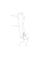
図1は、この発明の実施の形態1によるエレベータのかご移動規制装置(全体)を示す正面図である。図2は、本実施の形態1によるエレベータのかご移動規制装置(かご移動規制位置)の要部を示す斜視図である。図3は、図2のエレベータのかご移動規制装置(かご移動規制位置)の要部を示す側面図である。図4は、図3のエレベータのかご移動規制装置(かご移動規制位置)の要部を示す拡大図である。図5は、本実施の形態1によるエレベータのかご移動規制装置(かご移動許容位置)の要部を示す側面図である。図6は、図5のエレベータのかご移動規制装置(かご移動許容位置)の要部を示す拡大図である。図7は、本実施の形態1によるエレベータのかご移動規制装置の可動部材を示す拡大図(斜視図)である。図8は、本実施の形態1によるエレベータのかご移動規制装置の固定部材を示す拡大図(正面図)である。
Embodiment 1.
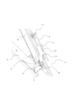
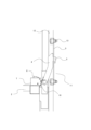
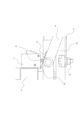
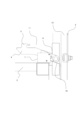
FIG. 1 is a front view showing an elevator car movement restriction device (whole) according to embodiment 1 of the present invention. FIG. 2 is a perspective view showing a main part of the elevator car movement restriction device (car movement restriction position) according to embodiment 1 of the present invention. FIG. 3 is a side view showing a main part of the elevator car movement restriction device (car movement restriction position) of FIG. 2. FIG. 4 is an enlarged view showing a main part of the elevator car movement restriction device (car movement restriction position) of FIG. 3. FIG. 5 is a side view showing a main part of the elevator car movement restriction device (car movement permitted position) of FIG. 1 according to embodiment 1 of the present invention. FIG. 6 is an enlarged view showing a main part of the elevator car movement restriction device (car movement permitted position) of FIG. 5. FIG. 7 is an enlarged view (perspective view) showing a movable member of the elevator car movement restriction device according to embodiment 1 of the present invention. FIG. 8 is an enlarged view (front view) showing a fixed member of the elevator car movement restriction device according to embodiment 1 of the present invention.
図において、本発明のかご移動規制装置11は、エレベータの昇降路1に設けられた固定部材3と、かご2に設けられ、かご移動規制位置およびかご移動許容位置の間で回動可能な可動部材4と、可動部材4がかご移動許容位置にある状態を検知するスイッチ6と、スイッチ6を保持する取付金7とを備える。
In the figure, the car
可動部材4は、回動可能にかご2に支持されている。図1に示されるように、可動部材4の一端に回動軸8が設けられている。回動軸8は、かご2に支持されている。可動部材4の他端には、固定部材3に係合可能な係合部5が設けられている。より詳細には、係合部5は、回動軸8を中心に、弧状に移動することができる。
The
固定部材3は、昇降路1と一体的な部分に支持されている。より詳細には、固定部材3は、昇降路1内に設けられたかごガイドレール12に、ボルト13によって固定されている。すなわち、固定部材3は、昇降路1に一体に支持されている。また、固定部材3は、板状の部材である。
The fixed
固定部材3には、貫通孔31が形成されている。可動部材4は、かご移動規制位置では、固定部材3に係合されるため、係合部5が貫通孔31に挿入されることとなる。可動部材4は、かご移動許容位置では、図1に示されるように、貫通孔31から退出している。
The fixed
つまり、可動部材4は、かご移動許容位置において、かご2の移動に伴い貫通孔31と当接する位置にはなく、かご2の移動に伴い貫通孔31と干渉しない位置にある。言い換えると、このように可動部材4が、かご2の移動に伴い貫通孔31と干渉しない位置にあるときが、可動部材4のかご移動許容位置である。
In other words, in the cage movement permitted position, the
回動軸8に近接するかご2には、取付金7が設けられており、取付金7には、可動部材4がかご移動規制位置にあることを検出するスイッチ6が取り付けられている。また、可動部材4の回動軸8側には、回動軸8と共に回動して、かご移動規制位置に配置されたとき、スイッチ6に当接して可動部材4がかご移動規制位置にある状態が検出される被検出部9が設けられている。
A
スイッチ6には、制御装置14が接続されている。制御装置14は、スイッチ6からの信号に応じて、かご2を昇降させる駆動装置15の制御を行っている。可動部材4には、被検出部9が取り付けられている。被検出部9は、可動部材4がかご移動規制位置にあるときに、スイッチ6の作動片と当接して、スイッチ6を作動状態にする。
A
スイッチ6は、常閉接点を有しており、安全回路に直列に接続されている。被検出部9によりスイッチ6が作動されると、すなわち、スイッチ6の接点が開くと、制御装置14により、駆動装置15への通電が、遮断される。これにより、可動部材4がかご移動許容位置にあるときは、駆動装置15によるかご2の運転が可能であるが、可動部材4がかご移動規制位置にあるときには、かご2の運転は阻止される。
The
また、可動部材4の回動軸8側には、可動部材4の長手方向に沿って回動軸8側に突出して形成されるストッパ部10が設けられている。ストッパ部10は、回動軸8を中心に、係合部5と逆方向に弧状に移動することができる。ストッパ部10は、板状の部材であり、可動部材4がかご移動規制位置にあるとき、取付金7の下端角部に当接して、可動部材4の回動を制限する。
In addition, a
ここで、可動部材4がかご移動規制位置にあるとき、係合部5は貫通孔31に挿入されており、被検出部9はスイッチ6に当接して、ストッパ部10は取付金7に当接して支持される。また、可動部材4がかご移動許容位置にあるとき、係合部5はかご2側に向けて固定部材3に干渉しない位置に配置されており、被検出部9及びストッパ部10はスイッチ6及び取付金7に干渉しない昇降路1側に向けて配置される。
When the
また、かご移動規制装置11をかご2に取付け調整する場合、かご2を固定部材3から離れた位置で停止させることがある。この場合、可動部材4は、かご移動規制位置に回動可能であるが、固定部材3の貫通孔31には挿入されない状態となる。この場合、可動部材4をかご移動規制位置に回動させたとき、ストッパ部10が取付金7に当接する。そのため、可動部材4及び被検出部9の回動は制限される。このとき、可動部材4がかご移動規制位置側へ回動しないため、被検出部9がスイッチ6に当接した状態が維持される。
In addition, when the car
次に、上記のように構成された実施の形態1の動作について説明する。始めに、可動部材4をかご2に取付ける。かご2の上部が固定部材3の近傍に配置するようにかご2を移動させる。可動部材4が貫通孔31に係合するように、かご2の上下位置を調整する。
Next, the operation of the first embodiment configured as described above will be described. First, the
可動部材4が貫通孔31に係合された状態で、予めスイッチ6が組み込まれた取付金7をかご2に取付ける。このとき、ストッパ部10の可動部材4から突出した端部が取付金7の下端角部に当接するように取付金7の位置を調整する。すなわち、取付金7のかご2との締結用の穴は長穴になっており、可動部材4が係合された状態で、ストッパ部10を取付金7に押し当てるように調整する。次に、取付金7の取付け位置を水平方向に移動しながら調整して、ストッパ部10の下端部と取付金7の下端角部とが当接し、かつ被検出部9がスイッチ6によって検出可能な位置に合わせる。
With the
次に、可動部材4をかご移動規制位置に配置したとき、ストッパ部10が取付金7に当接して、可動部材4がかご移動規制位置側にさらに回動しないように制限されることを確認する。ここで、いったん可動部材4の固定部材3との係合を解除させる。次に、かご2を上下方向に少し移動させて、可動部材4がかご移動規制位置またはかご移動許容位置のいずれにも回動可能な状態にして、ストッパ部10及び被検出部9の取付け位置を調整する。
Next, when the
最後に、可動部材4が固定部材3と係合されていない状態で、かつかご移動規制位置に配置された状態で、ストッパ部10が取付金7に当接して可動部材4の回動が制限されていること、被検出部9がスイッチ6に当接して正常に検出できたことを確認して調整完了となる。
Finally, with the
上記のように実施の形態1によれば、昇降路1に設けられた固定部材3と、かご2に設けられ、一端に回動軸8が形成されており、かご移動規制位置およびかご移動許容位置の間で回動可能であって、かご移動規制位置で他端が固定部材3と係合する可動部材4と、可動部材4がかご移動規制位置にある状態を検知するスイッチ6と、スイッチ6を保持する取付金7と、可動部材4の回動軸8側に設けられ、スイッチ6に当接して可動部材4が移動規制位置にある状態が検出される被検出部9と、を有するエレベータのかご移動規制装置11において、可動部材4の長手方向に沿って回動軸8側から突出して設けられ、可動部材4と共に回動可能であって、可動部材4がかご移動規制位置に回動したとき、取付金7に当接すると共に可動部材4のかご移動規制位置側への回動を規制するストッパ部10を備えたことにより、可動部材4をかご移動規制位置に回動したとき、さらにかご移動規制位置側へ回動することがないため、可動部材4によるスイッチ6の破損を防止可能なかご移動規制装置11を実現できる。また、取付金7を取り付ける際、かご移動規制位置でストッパ部10と取付金7とを当接させるだけで位置決めできるため、取付け位置が容易に調整可能なかご移動規制装置11を実現できる。
As described above, according to embodiment 1, the device has a fixed
なお、固定部材3は昇降路1に設けられ、可動部材4はかご1に設けられているが、必ずしもこの位置でなくても良い。例えば、固定部材3はかご1に設けられ、可動部材4は昇降路1に設けられていても良く、同様の作用・効果を奏することは言うまでもない。
Note that the fixed
また、かご移動規制位置でストッパ部10は取付金7に当接する構成であるが、必ずしも同じ構成でなくても良い。例えば、取付金7の代わりにストッパ部10が当接して同様の作用・効果を奏する部材をかご2に設けても良い。
In addition, the
また、かご移動規制装置11はエレベータのかご2に用いることができるが、必ずしもエレベータのかご2でなくても良い。例えば昇降路が無い建築用ゴンドラであっても、実施の形態1と同様の構成を備えていれば用いることができる。
In addition, the car
1 昇降路、2 かご、3 固定部材、4 可動部材、5 係合部、6 スイッチ、7 取付金、8 回動軸、9 被検出部、10 ストッパ部、11 かご移動規制装置、12 かごガイドレール、13 ボルト、14 制御装置、15 駆動装置 1 Elevator shaft, 2 Cage, 3 Fixed member, 4 Movable member, 5 Engagement part, 6 Switch, 7 Mounting bracket, 8 Rotating shaft, 9 Detectable part, 10 Stopper part, 11 Cage movement restriction device, 12 Cage guide rail, 13 Bolt, 14 Control device, 15 Drive device
本発明は、エレベータのかご移動規制装置に関するものである。 The present invention relates to an elevator car movement restriction device.
1 昇降路、2 かご、3 固定部材、4 可動部材、5 係合部、6 スイッチ、7 取付金、8 回動軸、9 被検出部、10 ストッパ部、11 かご移動規制装置、12 かごガイドレール、13 ボルト、14 制御装置、15 駆動装置 1 Elevator shaft, 2 Cage, 3 Fixed member, 4 Movable member, 5 Engagement part, 6 Switch, 7 Mounting bracket, 8 Rotating shaft, 9 Detectable part, 10 Stopper part, 11 Cage movement restriction device, 12 Cage guide rail, 13 Bolt, 14 Control device, 15 Drive device
Claims (1)
前記可動部材が前記かご移動規制位置にある状態を検知するスイッチと、前記スイッチを保持する取付金と、前記可動部材の前記回動軸側に設けられ、前記スイッチに当接して前記可動部材が前記移動規制位置にある状態が検出される被検出部と、を有するエレベータのかご移動規制装置において、
前記可動部材の長手方向に沿って前記回動軸側から突出して設けられ、前記可動部材と共に回動可能であって、前記可動部材が前記かご移動規制位置に回動したとき、前記取付金に当接すると共に前記可動部材の前記かご移動規制位置側への回動を規制するストッパ部を備えたことを特徴とするエレベータのかご移動規制装置。 a fixed member provided on one of the elevator shaft and the car; and a movable member provided on the other of the elevator shaft and the car, the movable member having a rotation shaft formed at one end and being rotatable between a car movement restricting position and a car movement allowing position, the other end of the movable member engaging with the fixed member at the car movement restricting position;
An elevator car movement restricting device comprising: a switch for detecting a state in which the movable member is at the car movement restricting position; a mounting bracket for holding the switch; and a detection target provided on the rotating shaft side of the movable member and contacting the switch to detect a state in which the movable member is at the movement restricting position,
An elevator car movement restricting device characterized in that it is provided with a stopper portion protruding from the pivot shaft side along the longitudinal direction of the movable member, capable of rotating together with the movable member, and abutting against the mounting bracket and restricting the rotation of the movable member toward the car movement restricting position when the movable member rotates to the car movement restricting position.
Priority Applications (2)
| Application Number | Priority Date | Filing Date | Title |
|---|---|---|---|
| JP2021042986A JP7608899B2 (en) | 2021-03-17 | 2021-03-17 | Elevator cage movement restriction device |
| CN202111120324.5A CN115108424B (en) | 2021-03-17 | 2021-09-24 | Elevator car movement limiting device |
Applications Claiming Priority (1)
| Application Number | Priority Date | Filing Date | Title |
|---|---|---|---|
| JP2021042986A JP7608899B2 (en) | 2021-03-17 | 2021-03-17 | Elevator cage movement restriction device |
Publications (2)
| Publication Number | Publication Date |
|---|---|
| JP2022142802A JP2022142802A (en) | 2022-10-03 |
| JP7608899B2 true JP7608899B2 (en) | 2025-01-07 |
Family
ID=83324466
Family Applications (1)
| Application Number | Title | Priority Date | Filing Date |
|---|---|---|---|
| JP2021042986A Active JP7608899B2 (en) | 2021-03-17 | 2021-03-17 | Elevator cage movement restriction device |
Country Status (2)
| Country | Link |
|---|---|
| JP (1) | JP7608899B2 (en) |
| CN (1) | CN115108424B (en) |
Citations (4)
| Publication number | Priority date | Publication date | Assignee | Title |
|---|---|---|---|---|
| WO2002098780A1 (en) | 2001-05-30 | 2002-12-12 | Mitsubishi Denki Kabushiki Kaisha | Elevator device and car movement limiting device thereof |
| US20100252369A1 (en) | 2007-12-21 | 2010-10-07 | Teemu Tolonen | Elevator and stop block arrangement for an elevator |
| WO2017119117A1 (en) | 2016-01-08 | 2017-07-13 | 三菱電機株式会社 | Cage movement restricting device and elevator |
| WO2018025312A1 (en) | 2016-08-01 | 2018-02-08 | 三菱電機株式会社 | Car fixing device for elevator |
Family Cites Families (11)
| Publication number | Priority date | Publication date | Assignee | Title |
|---|---|---|---|---|
| JP2005145693A (en) * | 2003-11-19 | 2005-06-09 | Mitsubishi Electric Corp | Elevator door equipment |
| JP4657776B2 (en) * | 2005-03-28 | 2011-03-23 | 三菱電機株式会社 | Elevator car fixing device |
| CN101134547B (en) * | 2006-08-30 | 2010-12-15 | 上海三菱电梯有限公司 | Elevator car fixing device |
| KR101537846B1 (en) * | 2009-10-28 | 2015-07-20 | 미쓰비시덴키 가부시키가이샤 | Emergency stop device for elevators |
| JP5863578B2 (en) * | 2012-06-26 | 2016-02-16 | 三菱電機株式会社 | Elevator safety device |
| JP6116444B2 (en) * | 2013-08-23 | 2017-04-19 | 三菱電機株式会社 | Lighting plate fall prevention device for ceiling lighting device in elevator cab, ceiling lighting device provided with the same, and method for removing lighting plate of ceiling lighting device |
| JP2016098106A (en) * | 2014-11-26 | 2016-05-30 | 三菱電機株式会社 | Car fixation device for elevator |
| CN107835781B (en) * | 2015-07-15 | 2019-06-25 | 三菱电机株式会社 | elevator installation |
| KR101768092B1 (en) * | 2016-05-30 | 2017-08-14 | (주)대한특수승강기 | Safety equipment for installing on elevator cage |
| WO2019064451A1 (en) * | 2017-09-28 | 2019-04-04 | 三菱電機株式会社 | Elevator car constraining apparatus |
| WO2019146058A1 (en) * | 2018-01-26 | 2019-08-01 | 三菱電機ビルテクノサービス株式会社 | Control device and elevator system having function maintaining elevator car position at position suitable for work |
-
2021
- 2021-03-17 JP JP2021042986A patent/JP7608899B2/en active Active
- 2021-09-24 CN CN202111120324.5A patent/CN115108424B/en active Active
Patent Citations (4)
| Publication number | Priority date | Publication date | Assignee | Title |
|---|---|---|---|---|
| WO2002098780A1 (en) | 2001-05-30 | 2002-12-12 | Mitsubishi Denki Kabushiki Kaisha | Elevator device and car movement limiting device thereof |
| US20100252369A1 (en) | 2007-12-21 | 2010-10-07 | Teemu Tolonen | Elevator and stop block arrangement for an elevator |
| WO2017119117A1 (en) | 2016-01-08 | 2017-07-13 | 三菱電機株式会社 | Cage movement restricting device and elevator |
| WO2018025312A1 (en) | 2016-08-01 | 2018-02-08 | 三菱電機株式会社 | Car fixing device for elevator |
Also Published As
| Publication number | Publication date |
|---|---|
| CN115108424B (en) | 2023-05-30 |
| JP2022142802A (en) | 2022-10-03 |
| CN115108424A (en) | 2022-09-27 |
Similar Documents
| Publication | Publication Date | Title |
|---|---|---|
| EP2571799B1 (en) | Integrated elevator safety system | |
| JP4680262B2 (en) | Safety devices used in elevator systems | |
| US9061865B2 (en) | Elevator cage departure monitoring device and method | |
| US20130248298A1 (en) | Safety brake device for an elevator installation | |
| CN109382805B (en) | Work support device capable of freely lifting | |
| JP7608899B2 (en) | Elevator cage movement restriction device | |
| JP6452857B2 (en) | Car movement restriction device and elevator | |
| JP6440731B2 (en) | Electronic component mounting system | |
| KR20170113868A (en) | Safety brake control apparatus for emergency stop of escalator | |
| JP6517372B2 (en) | Elevator equipment | |
| KR20170070617A (en) | Safety brake control apparatus for emergency stop of escalator | |
| JP6324525B2 (en) | Speed governor and elevator device | |
| JP5463229B2 (en) | Manual braking device for lifting scaffolds | |
| CN119911774B (en) | Car frame follow-up speed limiter and elevator | |
| CN222665074U (en) | Electronic safety tongs | |
| KR200268001Y1 (en) | Emergency breaking apparatus for escalator | |
| KR20050120324A (en) | Collision prevention device for an elevator | |
| JP2005041592A (en) | Elevating and guiding device for elevator | |
| CN115849130A (en) | Elevator self-adaptive operation method based on working environment | |
| JP2011102162A (en) | End point switch for elevator | |
| JP2003118409A (en) | Pto switch lever device | |
| JP2008063111A (en) | Passenger conveyor drive | |
| HK1151015A1 (en) | Buffer arrangement and buffer stop of an elevator | |
| JPS61146491A (en) | Safety device for robot | |
| HK1151015B (en) | Buffer arrangement and buffer stop of an elevator |
Legal Events
| Date | Code | Title | Description |
|---|---|---|---|
| A521 | Request for written amendment filed |
Free format text: JAPANESE INTERMEDIATE CODE: A523 Effective date: 20210317 |
|
| RD01 | Notification of change of attorney |
Free format text: JAPANESE INTERMEDIATE CODE: A7421 Effective date: 20220511 |
|
| A621 | Written request for application examination |
Free format text: JAPANESE INTERMEDIATE CODE: A621 Effective date: 20231122 |
|
| RD01 | Notification of change of attorney |
Free format text: JAPANESE INTERMEDIATE CODE: A7421 Effective date: 20240704 |
|
| A977 | Report on retrieval |
Free format text: JAPANESE INTERMEDIATE CODE: A971007 Effective date: 20241031 |
|
| TRDD | Decision of grant or rejection written | ||
| A01 | Written decision to grant a patent or to grant a registration (utility model) |
Free format text: JAPANESE INTERMEDIATE CODE: A01 Effective date: 20241119 |
|
| A61 | First payment of annual fees (during grant procedure) |
Free format text: JAPANESE INTERMEDIATE CODE: A61 Effective date: 20241202 |
|
| R150 | Certificate of patent or registration of utility model |
Ref document number: 7608899 Country of ref document: JP Free format text: JAPANESE INTERMEDIATE CODE: R150 |