EP1433977A2 - Shock absorber and overload protection device - Google Patents
Shock absorber and overload protection device Download PDFInfo
- Publication number
- EP1433977A2 EP1433977A2 EP04007844A EP04007844A EP1433977A2 EP 1433977 A2 EP1433977 A2 EP 1433977A2 EP 04007844 A EP04007844 A EP 04007844A EP 04007844 A EP04007844 A EP 04007844A EP 1433977 A2 EP1433977 A2 EP 1433977A2
- Authority
- EP
- European Patent Office
- Prior art keywords
- disk
- rotary disk
- shock absorber
- rotary
- stationary
- Prior art date
- Legal status (The legal status is an assumption and is not a legal conclusion. Google has not performed a legal analysis and makes no representation as to the accuracy of the status listed.)
- Granted
Links
- 230000035939 shock Effects 0.000 title claims abstract description 66
- 239000006096 absorbing agent Substances 0.000 title claims abstract description 49
- 239000007858 starting material Substances 0.000 claims abstract description 12
- 238000005096 rolling process Methods 0.000 claims abstract description 9
- 239000002994 raw material Substances 0.000 claims abstract description 6
- 239000004519 grease Substances 0.000 description 24
- 239000002184 metal Substances 0.000 description 5
- 230000005540 biological transmission Effects 0.000 description 4
- 210000000078 claw Anatomy 0.000 description 4
- 230000002093 peripheral effect Effects 0.000 description 4
- 230000000694 effects Effects 0.000 description 3
- 230000007423 decrease Effects 0.000 description 1
- 238000004519 manufacturing process Methods 0.000 description 1
- 230000000149 penetrating effect Effects 0.000 description 1
Images


Classifications
-
- F—MECHANICAL ENGINEERING; LIGHTING; HEATING; WEAPONS; BLASTING
- F02—COMBUSTION ENGINES; HOT-GAS OR COMBUSTION-PRODUCT ENGINE PLANTS
- F02N—STARTING OF COMBUSTION ENGINES; STARTING AIDS FOR SUCH ENGINES, NOT OTHERWISE PROVIDED FOR
- F02N15/00—Other power-operated starting apparatus; Component parts, details, or accessories, not provided for in, or of interest apart from groups F02N5/00 - F02N13/00
- F02N15/02—Gearing between starting-engines and started engines; Engagement or disengagement thereof
- F02N15/04—Gearing between starting-engines and started engines; Engagement or disengagement thereof the gearing including disengaging toothed gears
- F02N15/06—Gearing between starting-engines and started engines; Engagement or disengagement thereof the gearing including disengaging toothed gears the toothed gears being moved by axial displacement
- F02N15/062—Starter drives
- F02N15/063—Starter drives with resilient shock absorbers
-
- F—MECHANICAL ENGINEERING; LIGHTING; HEATING; WEAPONS; BLASTING
- F02—COMBUSTION ENGINES; HOT-GAS OR COMBUSTION-PRODUCT ENGINE PLANTS
- F02N—STARTING OF COMBUSTION ENGINES; STARTING AIDS FOR SUCH ENGINES, NOT OTHERWISE PROVIDED FOR
- F02N15/00—Other power-operated starting apparatus; Component parts, details, or accessories, not provided for in, or of interest apart from groups F02N5/00 - F02N13/00
- F02N15/02—Gearing between starting-engines and started engines; Engagement or disengagement thereof
- F02N15/04—Gearing between starting-engines and started engines; Engagement or disengagement thereof the gearing including disengaging toothed gears
- F02N15/043—Gearing between starting-engines and started engines; Engagement or disengagement thereof the gearing including disengaging toothed gears the gearing including a speed reducer
- F02N15/046—Gearing between starting-engines and started engines; Engagement or disengagement thereof the gearing including disengaging toothed gears the gearing including a speed reducer of the planetary type
-
- F—MECHANICAL ENGINEERING; LIGHTING; HEATING; WEAPONS; BLASTING
- F16—ENGINEERING ELEMENTS AND UNITS; GENERAL MEASURES FOR PRODUCING AND MAINTAINING EFFECTIVE FUNCTIONING OF MACHINES OR INSTALLATIONS; THERMAL INSULATION IN GENERAL
- F16D—COUPLINGS FOR TRANSMITTING ROTATION; CLUTCHES; BRAKES
- F16D65/00—Parts or details
- F16D65/02—Braking members; Mounting thereof
- F16D65/12—Discs; Drums for disc brakes
-
- F—MECHANICAL ENGINEERING; LIGHTING; HEATING; WEAPONS; BLASTING
- F16—ENGINEERING ELEMENTS AND UNITS; GENERAL MEASURES FOR PRODUCING AND MAINTAINING EFFECTIVE FUNCTIONING OF MACHINES OR INSTALLATIONS; THERMAL INSULATION IN GENERAL
- F16F—SPRINGS; SHOCK-ABSORBERS; MEANS FOR DAMPING VIBRATION
- F16F15/00—Suppression of vibrations in systems; Means or arrangements for avoiding or reducing out-of-balance forces, e.g. due to motion
- F16F15/10—Suppression of vibrations in rotating systems by making use of members moving with the system
- F16F15/12—Suppression of vibrations in rotating systems by making use of members moving with the system using elastic members or friction-damping members, e.g. between a rotating shaft and a gyratory mass mounted thereon
- F16F15/131—Suppression of vibrations in rotating systems by making use of members moving with the system using elastic members or friction-damping members, e.g. between a rotating shaft and a gyratory mass mounted thereon the rotating system comprising two or more gyratory masses
- F16F15/139—Suppression of vibrations in rotating systems by making use of members moving with the system using elastic members or friction-damping members, e.g. between a rotating shaft and a gyratory mass mounted thereon the rotating system comprising two or more gyratory masses characterised by friction-damping means
- F16F15/1397—Overload protection, i.e. means for limiting torque
-
- F—MECHANICAL ENGINEERING; LIGHTING; HEATING; WEAPONS; BLASTING
- F16—ENGINEERING ELEMENTS AND UNITS; GENERAL MEASURES FOR PRODUCING AND MAINTAINING EFFECTIVE FUNCTIONING OF MACHINES OR INSTALLATIONS; THERMAL INSULATION IN GENERAL
- F16H—GEARING
- F16H35/00—Gearings or mechanisms with other special functional features
- F16H35/10—Arrangements or devices for absorbing overload or preventing damage by overload
-
- F—MECHANICAL ENGINEERING; LIGHTING; HEATING; WEAPONS; BLASTING
- F16—ENGINEERING ELEMENTS AND UNITS; GENERAL MEASURES FOR PRODUCING AND MAINTAINING EFFECTIVE FUNCTIONING OF MACHINES OR INSTALLATIONS; THERMAL INSULATION IN GENERAL
- F16D—COUPLINGS FOR TRANSMITTING ROTATION; CLUTCHES; BRAKES
- F16D65/00—Parts or details
- F16D65/02—Braking members; Mounting thereof
- F16D2065/13—Parts or details of discs or drums
- F16D2065/1304—Structure
- F16D2065/1312—Structure circumferentially segmented
-
- F—MECHANICAL ENGINEERING; LIGHTING; HEATING; WEAPONS; BLASTING
- F16—ENGINEERING ELEMENTS AND UNITS; GENERAL MEASURES FOR PRODUCING AND MAINTAINING EFFECTIVE FUNCTIONING OF MACHINES OR INSTALLATIONS; THERMAL INSULATION IN GENERAL
- F16D—COUPLINGS FOR TRANSMITTING ROTATION; CLUTCHES; BRAKES
- F16D69/00—Friction linings; Attachment thereof; Selection of coacting friction substances or surfaces
- F16D2069/004—Profiled friction surfaces, e.g. grooves, dimples
-
- Y—GENERAL TAGGING OF NEW TECHNOLOGICAL DEVELOPMENTS; GENERAL TAGGING OF CROSS-SECTIONAL TECHNOLOGIES SPANNING OVER SEVERAL SECTIONS OF THE IPC; TECHNICAL SUBJECTS COVERED BY FORMER USPC CROSS-REFERENCE ART COLLECTIONS [XRACs] AND DIGESTS
- Y10—TECHNICAL SUBJECTS COVERED BY FORMER USPC
- Y10S—TECHNICAL SUBJECTS COVERED BY FORMER USPC CROSS-REFERENCE ART COLLECTIONS [XRACs] AND DIGESTS
- Y10S29/00—Metal working
- Y10S29/032—Rolling with other step
-
- Y—GENERAL TAGGING OF NEW TECHNOLOGICAL DEVELOPMENTS; GENERAL TAGGING OF CROSS-SECTIONAL TECHNOLOGIES SPANNING OVER SEVERAL SECTIONS OF THE IPC; TECHNICAL SUBJECTS COVERED BY FORMER USPC CROSS-REFERENCE ART COLLECTIONS [XRACs] AND DIGESTS
- Y10—TECHNICAL SUBJECTS COVERED BY FORMER USPC
- Y10T—TECHNICAL SUBJECTS COVERED BY FORMER US CLASSIFICATION
- Y10T74/00—Machine element or mechanism
- Y10T74/13—Machine starters
- Y10T74/131—Automatic
- Y10T74/132—Separate power mesher
Definitions
- the present invention relates to a shock absorber for absorbing a shock.
- JP-A-63-277859 discloses a starter equipped with a shock absorber for interrupting transmission of an excessive torque.
- a shock absorber for a starter a rotary disk is pressed against a stationary disk to generate a frictional force so that rotation of the rotary disk can be controlled. Accordingly, when a shock that is more than a certain normal torque is applied to the rotary disk, the rotary disk slips or rotates, thereby absorbing the shock.
- Such a rotary disk has a plurality of dimples and small banks formed around the dimples at a height of about tens of microns, providing a press-formed frictional surface.
- An amount of grease is filled in the spaces (dimples) between the stationary disk and the rotary disk with the banks being in contact with the surface of the stationary disk to prevent seizing.
- an array direction of the dimples is the same as the direction of the rolling of the raw material of the rotary disk, the height of the banks are not formed even. That is, the bank of the sides in parallel with the direction of rolling is lower than the bank of the sides that is perpendicular to the direction of rolling. Only two sides of the rectangular dimples can touch the stationary disk. Therefore, the two side-banks may be worn away more easily than the four side-banks. This lowers the lifetime of the shock absorber.
- the invention has been made in view of the above problem and has an object of providing a shock absorber that can make the height of the banks (or raised portions ) of the rectangular dimples even.
- rotary disk of a shock absorber has a plurality of press-formed rectangular dimples at a surface opposite the stationary disk.
- the rectangular dimples have four sides that incline to a direction of rolling of the raw material of the rotary disk. In such a case, the difference in height between the four side banks can be effectively reduced so that four banks can touch the stationary disk evenly.
- each the rectangular dimples may be square dimples.
- each side of the square shape inclines to the direction of rolling at 45 degree in angle.
- the plurality of rectangular dimples can be formed on the surface, of the stationary disk instead of the rotary disk.
- a rotary disk of the shock absorber has an oil hole or an oil groove as an oil reservoir.
- the oil hole or oil groove penetrates the rotary disk in the thickness direction.
- the rotary disk has a plurality of oil holes at circumferentially and radially different positions, and the plurality of oil holes are disposed so that the radial positions thereof partially overlap each other on a circumference of the rotary disk.
- a plurality of rotation loci of the oil holes is formed to partly overlap each other.
- the supply of the grease is not stopped in the radial direction of the rotary disk where the plurality of the oil holes are formed, so that the grease can be continuously and uniformly supplied to the friction surface of the rotary disk.
- the plurality of oil holes is preferably disposed spiral about the center of the rotary disk over the circumference of the rotary disk.
- the plurality of oil holes is dispersed evenly in the circumferential and radial directions so that the flatness of the rotary disk's surface opposite the stationary disk can be secured. This prevents uneven contacts with the stationary disk.
- the rotary disk can have a first one of the oil holes that opens radially outward and a second one of the oil holes that opens radially inward, and the first one and the second one of the oil holes extend to partially overlap each other in the radial direction. Accordingly, the first one and the second one of the oil holes partially overlap each other when the rotary disk rotates. Therefore, the grease can be supplied evenly to the friction surface of the rotary disk.
- the rigidity of the rotary disk becomes smaller than the oil holes not open to either outward or inward, so that the rotary disk can deform along the stationary disk. This equalizes the pressure on the surface of the rotary disk to result in even frictional wear, so that the lifetime of the rotary disk can be increased.
- the first one and second one of the oil holes preferably incline to the rotational direction from radial directions, so that the grease can enter the first and the second ones of the oil holes while the rotary disk rotates.
- the grease can be continuously supplied to the friction surface of the rotary disk.
- the stationary disk of the shock absorber can have oil reservoirs instead of the rotary disk.
- a rotary disk of a shock absorber is comprised of a plurality of circumferentially divided pieces.
- each divided piece can have a high flatness. As a result, pressure can be applied to each divided piece evenly, so that the surface pressure of the rotary disk can be made even.
- a stationary disk can have a plurality of circumferentially divided pieces, instead of the rotary disk.
- starter 1 includes a speed reduction unit, output shaft 2 and a shock absorber according to a first embodiment of the invention.
- the speed reduction unit reduces the rotation speed of later described starter motor and transmits it to output shaft 2.
- the shock absorber absorbs an excessive torque or a shock applied to the speed reduction unit.
- the starter motor is a well-known DC motor that is comprised of armature 3, stator poles 4, yoke 5 and brushes 6.
- armature 3 When a key switch is turned on and a pair of internal contacts of magnet switch 7 is closed, armature 3 is energized through brushes 6 to rotate.
- Magnet switch 7 opens or closes the internal contacts as a plunger (not shown) moves to drive pinion gear 9, together with one-way clutch 10, back and forth.
- Pinion gear 9 is slidably fitted to the outer periphery of output shaft 2 via bearing 11. Pinion gear 9 is driven forward (to the left in Fig. 3) together with one-way clutch 10 by lever 8 to engage engine ring gear 12 to transmit the torque to ring gear 12.
- One way clutch 10 is fitted to the outer periphery of output shaft 2 via a helical spline to transmit the rotation of output shaft 2 to pinion gear 9 and to interrupt transmission of torque between output shaft 2 and pinion gear 9.
- the speed reduction unit is comprised of sun gear 13, ring-shaped internal gear 14 having internal teeth at portions around sun gear 13, and planetary gears 14 disposed between sun gear 13 and internal gear 14 to mesh the same.
- Sun gear 13 has external teeth formed around the outer periphery of armature shaft 3a.
- the speed reduction unit and the shock absorber are covered by center case 16, which is described below.
- Internal gear 14 is provided with cylindrical outer wall 14a, which is rotatably fitted into the inner periphery of outer cylindrical portion 16c of center case 16. Internal gear 14 is connected with rotary disk 20 at an axial end of outer wall 14a and is restricted to rotate as rotary disk 20 is at a standstill. A plurality of recesses 14b is formed at the inner periphery of the axial end of outer wall 14a at equal intervals.
- Planetary gear 15 meshes sun gear 13 and internal gear 14, and is rotatably supported by pin 17 force-fitted to a rear portion of output shaft 2 via bearing 18.
- Center piece 16 has annular front wall 16a disposed perpendicularly to output shaft 2, inner cylindrical portion 16b extending axially rearward from the inner peripheral edge of front wall 16a, and outer cylindrical portion 16c extending from the outer peripheral edge of front wall 16a.
- the rear edge of outer cylindrical portion 16c is connected with the front edge of yoke 5, and the inner periphery of inner cylindrical portion 16b rotatably supports output shaft 2 via bearing 19.
- Male screw 16d is formed on the outer periphery of inner cylindrical portion 16b.
- Shock absorber is comprised of rotary disk 20, stationary disk 21, disc spring 22, and adjust screw 23.
- rotary disk 20 is a press-formed metal ring.
- Rotary disk 20 is disposed in contact with front wall 16a and is detained in internal gear 14 by a plurality of claws 20a, which are formed at the circumference of outer wall 14a, respectively inserted into the plurality of recesses 14b.
- a plurality of projections or banks 24 is formed at opposite surface of rotary disk 20.
- Banks 24 are formed when a plurality of dimples 25 (depressions) are press-formed at the surfaces of rotary disk 20.
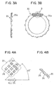
- Square dimples 25 are formed by square-pole punches (not shown), and four sides of the square dimples respectively incline 45 degree in angle to a direction of rolling of the raw material of rotary disk 20.
- Stationary disk 21 is also a press-formed metal ring similar to rotary disk 20, and is disposed in contact with the frictional surface of rotary disk 20.
- Stationary disk 21 has a plurality of circumferentially disposed openings 21a.
- a plurality of projections 16e is formed at front wall 16a and respectively inserted into openings 21a so that the rotation of stationary disk 21 can be stopped by center case 16.
- Disc spring 22 is a common spring for pushing stationary disk 21 toward rotary disk 20.
- Adjust screw 23 engages male screw 16d of inner cylindrical portion 16b of center case 16 to adjust an initial load of disc spring 22 according to the screw-in distance thereof.
- the key switch is turned off to deenergize the coil, the plunger returns to the initial position, so that pinion gear 9 separates from ring gear 12 and goes back along output shaft 2. Then, the internal switch of magnet switch 7 opens to cut electric supply to armature 3 to stop the same.
- Dimples 25 can be formed on stationary disk 21.
- Corners of each dimple may be either sharp or round.
- the shock absorber according to the invention can be applied to a drive unit other than the starter, such as a brake or a clutch.
- shock absorber according to a second embodiment of the invention will be described with reference to Figs. 5A and 5B.
- Rotary disk 20 is a press-formed metal ring.
- Rotary disk 20 is disposed in contact with front wall 16a and is detained in internal gear 14 by a plurality of claws 20a, which are formed at the circumference of outer wall 14a, respectively inserted into the plurality of recesses 14b.
- a plurality of projections or banks (not shown) is formed at opposite surfaces of rotary disk 20 in the same manner as described with reference to Figs. 3A and 3B.
- Banks 24 are formed when a plurality of dimples 25 (depressions/not shown) is press-formed at the surfaces of rotary disk 20.
- rotary disk 20 has a plurality of oil holes 24 penetrating the same in the thickness direction.
- the plurality of oil holes 24 is disposed almost evenly in the circumferential direction.
- Each group of four circumferentially lined oil holes 24 forms a spiral line about the center O of rotary disk 20 thereof so that the radial position thereof overlaps one another.
- first oil hole 24a partially overlaps each other on a circumference of rotary disk 20.
- Second oil hole 24b and third oil hole 24c also partially overlap each other, and third oil hole 24c and fourth oil hole 24d partially overlap each other, on circumferences of rotary disk 20.
- oil hole group 24A A plurality of oil hole groups 24A is disposed in succession all around rotary disk 20. That is, first oil hole 24a of one group 24A overlaps in the radial direction with (or can be located with the same circumferential position as) fourth oil hole 24d of another group 24 adjacent thereto. However, first oil hole 24a of one group 24A and fourth oil hole 24d of another group 24A, as shown in Fig. 5B, are preferably located at the same circumferential position of rotary disk 20 as one of the plurality of claws 20a.
- Stationary disk 21 is also a press-formed metal ring similar to rotary disk 20, and is disposed in contact with the frictional surface of rotary disk 20. As described in the first embodiment with reference to Fig. 2, stationary disk 21 also has a plurality of circumferentially disposed openings 21a. A plurality of projections 16e is formed at front wall 16a and is respectively inserted into openings 21a so that the rotation of stationary disk 21 can be stopped by center case 16.
- Disc spring 22 is a common spring for pushing stationary disk 21 toward rotary disk 20.
- Adjust screw 23 engages male screw 16d of inner cylindrical portion 16b of center case 16 to adjust an initial load of disc spring 22 according to a screw-in distance thereof.
- a plurality of loci of oil holes 24 is formed in the radial direction of rotary disk 20 (four in this embodiment). Because the plurality of loci partly overlaps one another, the supply of the grease from the range between first oil hole 24a and fourth oil hole 24d may not be intermitted in the radial direction of rotary disk 20. As a result, the grease can be supplied to the friction surface of rotary disk 20 evenly, so that an excellent slip torque can be obtained.
- a plurality of oil hole group 24A is formed spiral about the center O of rotary disk 20. This can supply the grease all around the friction surface of rotary disk 20 with a minimum number of oil holes.
- first oil hole 24a of one group and fourth oil hole 24d of another group can be located where claws 20a are located. This prevents the rigidity of rotary disk 20 from lowering.
- Rotary disk 20 of a shock absorber according to a third embodiment of the invention is described with reference to Fig. 6.
- Oil holes at the inner peripheral edge (or the outer peripheral edge) of rotary disk 20 can open inward. In this case, the same effect as the second embodiment can be obtained.
- Oil recesses or reservoirs 25 and 26 are formed on the surface of center case 16 and on the surface of stationary disk 21 opposite the friction surfaces of rotary disk 20. If a through hole for oil recess 25 is formed at wall 16a to penetrate the same in the thickness direction, grease may leak out of center case. A recess is also formed for oil reservoir 26 at stationary disk 21. Oil recesses 25 and 26 are preferably formed at the same positions as oil holes 24, which are radially and circumferentially different from each other but overlap each other.
- oil hole 24 formed at rotary disk 20 can be obtained. If oil recesses 25, 26 are formed at front wall 16a and stationary disk 21, the number of oil holes 24 of rotary disk 20 can be reduced or eliminated.
- oil holes 24 prevent rotary disk 20 from reducing the strength thereof.
- a rotary disk 20 of a shock absorber according to a fifth embodiment is described with reference to Figs. 8A and 8B.
- Rotary disk 20 is provided with oil grooves 27.
- Each oil groove 27 is formed to penetrate rotary disk 20 in the thickness direction and to extend long and narrowly in the radial direction to hold grease as oil hole 24.
- Oil grooves 27 are formed of a plurality of first oil grooves 27a which opens radially outward and a plurality of second oil grooves 27b which opens radially inward.
- oil grooves 27a and 27b are alternately disposed in the circumferential direction.
- Each first oil groove 27a and each second oil groove 27b overlap each other at the bottom portion thereof in the radial direction if they are put side by side in the circumferential direction.
- the radially inner head portion of first oil grooves 27a is formed to extend beyond the centerline of the width of rotary disk 20 (one-dot chain line in Fig. 8B).
- the radially outer bottom portion of second oil grooves 27b is formed to extend beyond the centerline.
- First oil groove 27a opens outward at the outer periphery of rotary disk 20
- second oil groove 27b opens inward at the inner periphery of rotary disk 20. Therefore, rotary disk 20 becomes flexible so that rotary disk 20 can easily deform along stationary disk. As a result, the surface pressure of rotary disk 20 becomes more uniform, and the friction surface can wear away uniformly. This increases the lifetime of rotary disk 20.
- a shock absorber according to a sixth embodiment of the invention is described with reference to Figs. 9A and 9B.
- Oil grooves 27 are formed at rotary disk 20. First oil grooves 27a and second oil grooves 27b incline to the rotation direction of rotary disk 20.
- a shock absorber according to a seventh embodiment is described with reference to Figs. 10 and 11.
- a plurality of projections or banks (not shown) is formed at opposite surfaces of rotary disk 20.
- the plurality of banks is formed when a plurality of dimples is press-formed at the surfaces of rotary disk 20.
- Rotary disk 20 is formed of a plurality of divided pieces 20A, as shown in Fig. 10. Because the plurality of divided pieces 20A is stamped out from portions of metal plate 24 close to each other, as shown in Fig. 11, each divided piece 20A can have a high flatness, so that the yield rate of the raw material is high. In addition, because each divided piece 20A is disposed in a circle at small intervals, it is possible to fill grease in gaps between divided pieces 20A. In order to prevent each divided piece 20A from moving to the inner periphery thereby to remove the gaps, center case 16 is provided with a circular support for supporting the inner periphery of rotary disk 20.
- the spring force of disk spring 22 can be evenly applied to each divided piece 20A, so that the surface pressure of rotary disk 20 can be made even. In other words, partial contact of rotary disk 20 with front wall 16a and stationary disk 21 can be prevented. This reduces wear of the friction surface and increases the lifetime of the shock absorber.
- stationary disk 21 can also divided in the circumferential direction.
- shock absorbers according to the above embodiments can be applied to any driving device other than a starter, such as a brake or a clutch.
Landscapes
- Engineering & Computer Science (AREA)
- General Engineering & Computer Science (AREA)
- Mechanical Engineering (AREA)
- Chemical & Material Sciences (AREA)
- Combustion & Propulsion (AREA)
- Physics & Mathematics (AREA)
- Acoustics & Sound (AREA)
- Aviation & Aerospace Engineering (AREA)
- Fluid-Damping Devices (AREA)
- Vibration Dampers (AREA)
- Mechanical Operated Clutches (AREA)
Abstract
Description
- The present invention relates to a shock absorber for absorbing a shock.
- JP-A-63-277859 discloses a starter equipped with a shock absorber for interrupting transmission of an excessive torque. In such a shock absorber for a starter, a rotary disk is pressed against a stationary disk to generate a frictional force so that rotation of the rotary disk can be controlled. Accordingly, when a shock that is more than a certain normal torque is applied to the rotary disk, the rotary disk slips or rotates, thereby absorbing the shock.
- Such a rotary disk has a plurality of dimples and small banks formed around the dimples at a height of about tens of microns, providing a press-formed frictional surface. An amount of grease is filled in the spaces (dimples) between the stationary disk and the rotary disk with the banks being in contact with the surface of the stationary disk to prevent seizing.
- Because an array direction of the dimples is the same as the direction of the rolling of the raw material of the rotary disk, the height of the banks are not formed even. That is, the bank of the sides in parallel with the direction of rolling is lower than the bank of the sides that is perpendicular to the direction of rolling. Only two sides of the rectangular dimples can touch the stationary disk. Therefore, the two side-banks may be worn away more easily than the four side-banks. This lowers the lifetime of the shock absorber.
- If another two-side banks start touching the stationary disk after the first two side-banks initially touched the stationary disk have worn away, the friction factor changes too abruptly to control the transmission torque.
- As the rotary disk has rotated for a long time, the spaces for the grease between the head of the dimple and the bottom thereof become narrower. Accordingly, a sufficient amount of grease can not be supplied to the sliding surfaces of the disks. This causes the seizing and shortens the lifetime.
- The invention has been made in view of the above problem and has an object of providing a shock absorber that can make the height of the banks (or raised portions ) of the rectangular dimples even.
- According to a main feature of the invention, rotary disk of a shock absorber has a plurality of press-formed rectangular dimples at a surface opposite the stationary disk. The rectangular dimples have four sides that incline to a direction of rolling of the raw material of the rotary disk. In such a case, the difference in height between the four side banks can be effectively reduced so that four banks can touch the stationary disk evenly.
- Preferably, each the rectangular dimples may be square dimples. In such a case, each side of the square shape inclines to the direction of rolling at 45 degree in angle.
- The plurality of rectangular dimples can be formed on the surface, of the stationary disk instead of the rotary disk.
- According to another feature of the invention, a rotary disk of the shock absorber has an oil hole or an oil groove as an oil reservoir. The oil hole or oil groove penetrates the rotary disk in the thickness direction.
- Even if the surface of the rotary disk wears away to some extent, the oil hole or oil groove does not disappear, so that grease can be prevented from reducing. The grease filled in the oil hole or oil groove is supplied to the sliding surfaces as long as the rotary disk rotates, so that the seizing can be prevented.
- Preferably, the rotary disk has a plurality of oil holes at circumferentially and radially different positions, and the plurality of oil holes are disposed so that the radial positions thereof partially overlap each other on a circumference of the rotary disk. When the rotary disk rotates, a plurality of rotation loci of the oil holes is formed to partly overlap each other.
- Accordingly, the supply of the grease is not stopped in the radial direction of the rotary disk where the plurality of the oil holes are formed, so that the grease can be continuously and uniformly supplied to the friction surface of the rotary disk.
- The plurality of oil holes is preferably disposed spiral about the center of the rotary disk over the circumference of the rotary disk. The plurality of oil holes is dispersed evenly in the circumferential and radial directions so that the flatness of the rotary disk's surface opposite the stationary disk can be secured. This prevents uneven contacts with the stationary disk.
- The rotary disk can have a first one of the oil holes that opens radially outward and a second one of the oil holes that opens radially inward, and the first one and the second one of the oil holes extend to partially overlap each other in the radial direction. Accordingly, the first one and the second one of the oil holes partially overlap each other when the rotary disk rotates. Therefore, the grease can be supplied evenly to the friction surface of the rotary disk.
- In addition, the rigidity of the rotary disk becomes smaller than the oil holes not open to either outward or inward, so that the rotary disk can deform along the stationary disk. This equalizes the pressure on the surface of the rotary disk to result in even frictional wear, so that the lifetime of the rotary disk can be increased.
- The first one and second one of the oil holes preferably incline to the rotational direction from radial directions, so that the grease can enter the first and the second ones of the oil holes while the rotary disk rotates. In other words, the grease can be continuously supplied to the friction surface of the rotary disk.
- The stationary disk of the shock absorber can have oil reservoirs instead of the rotary disk.
- In this case, the same effect as the rotary disk having the oil reservoir can be obtained. Therefore, reduction in strength of the rotary disk can be avoided.
- According to another feature of the invention, a rotary disk of a shock absorber is comprised of a plurality of circumferentially divided pieces.
- Because the surface area of each the divided piece is small relative to the entire surface area of the rotary disk, each divided piece can have a high flatness. As a result, pressure can be applied to each divided piece evenly, so that the surface pressure of the rotary disk can be made even.
- A stationary disk can have a plurality of circumferentially divided pieces, instead of the rotary disk.
- Other objects, features and characteristics' of the present invention as well as the functions of related parts of the present invention will become clear from a study of the following detailed description, the appended claims and the drawings. In the drawings:
- Fig. 1 is a half cross-sectional longitudinal view of a starter;
- Fig. 2 is an enlarged fragmentary cross-sectional view illustrating a main portion of a speed reduction unit and a shock absorber according to a first embodiment of the invention;
- Fig. 3A is a cross-sectional side view of a rotary disk of the shock absorber according to the first embodiment, and Fig. 3B is a plan view of the same;
- Fig. 4A is a plan view illustrating an array of dimples formed on the rotary disk and Fig. 4B is a cross-sectional view of the same cut along line IVB-IVB;
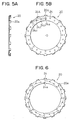
- Fig. 5A is a cross-sectional side view of a rotary disk of the shock absorber according to a second embodiment of the invention, and Fig. 5B is a plan view of the same;
- Fig. 6 is a plan view of a rotary disk of a shock absorber according to a third embodiment of the invention;
- Fig. 7 is a fragmentary enlarged cross-sectional view of a main portion of a shock absorber according to a fourth embodiment of the invention;
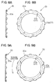
- Fig. 8 A is a cross-sectional side view of a rotary disk of a shock absorber according to a fifth embodiment of the invention, and Fig. 8B is a plan view of the same;
- Fig. 9 A is a cross-sectional side view of a rotary disk of a shock absorber according to a sixth embodiment of the invention, and Fig. 9B is a plan view of the same;
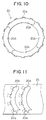
- Fig. 10 is a plan view of a rotary disk of a shock absorber according to a seventh embodiment of the invention; and
- Fig. 11 is a plan view illustrating a method of manufacturing divided pieces that form the rotary disk of the shock absorber according to the seventh embodiment.
-
- Shock absorber according to a first embodiment of the invention that is mounted into a starter is described with reference to Figs. 1 - 4.
- As shown in Fig. 1, starter 1 includes a speed reduction unit,
output shaft 2 and a shock absorber according to a first embodiment of the invention. The speed reduction unit reduces the rotation speed of later described starter motor and transmits it tooutput shaft 2. The shock absorber absorbs an excessive torque or a shock applied to the speed reduction unit. - The starter motor is a well-known DC motor that is comprised of
armature 3,stator poles 4,yoke 5 and brushes 6. When a key switch is turned on and a pair of internal contacts ofmagnet switch 7 is closed,armature 3 is energized throughbrushes 6 to rotate. -
Magnet switch 7 opens or closes the internal contacts as a plunger (not shown) moves to drivepinion gear 9, together with one-way clutch 10, back and forth. -
Pinion gear 9 is slidably fitted to the outer periphery ofoutput shaft 2 via bearing 11.Pinion gear 9 is driven forward (to the left in Fig. 3) together with one-way clutch 10 bylever 8 to engageengine ring gear 12 to transmit the torque to ringgear 12. - One way clutch 10 is fitted to the outer periphery of
output shaft 2 via a helical spline to transmit the rotation ofoutput shaft 2 topinion gear 9 and to interrupt transmission of torque betweenoutput shaft 2 andpinion gear 9. - The speed reduction unit is comprised of
sun gear 13, ring-shapedinternal gear 14 having internal teeth at portions aroundsun gear 13, andplanetary gears 14 disposed betweensun gear 13 andinternal gear 14 to mesh the same.Sun gear 13 has external teeth formed around the outer periphery ofarmature shaft 3a. The speed reduction unit and the shock absorber are covered bycenter case 16, which is described below. -
Internal gear 14 is provided with cylindricalouter wall 14a, which is rotatably fitted into the inner periphery of outercylindrical portion 16c ofcenter case 16.Internal gear 14 is connected withrotary disk 20 at an axial end ofouter wall 14a and is restricted to rotate asrotary disk 20 is at a standstill. A plurality of recesses 14b is formed at the inner periphery of the axial end ofouter wall 14a at equal intervals. -
Planetary gear 15meshes sun gear 13 andinternal gear 14, and is rotatably supported bypin 17 force-fitted to a rear portion ofoutput shaft 2 viabearing 18. - When
sun gear 13 is rotated byarmature 3,planetary gear 15 rotates on its axis and revolves aroundsun gear 13. Thus, revolution ofplanetary gear 15 is transmitted throughpin 17 tooutput shaft 2 to rotateoutput shaft 2. -
Center piece 16 has annularfront wall 16a disposed perpendicularly tooutput shaft 2, innercylindrical portion 16b extending axially rearward from the inner peripheral edge offront wall 16a, and outercylindrical portion 16c extending from the outer peripheral edge offront wall 16a. The rear edge of outercylindrical portion 16c is connected with the front edge ofyoke 5, and the inner periphery of innercylindrical portion 16b rotatably supportsoutput shaft 2 viabearing 19.Male screw 16d is formed on the outer periphery of innercylindrical portion 16b. - Shock absorber is comprised of
rotary disk 20,stationary disk 21,disc spring 22, and adjust screw 23. - As shown in Fig. 1,
rotary disk 20 is a press-formed metal ring.Rotary disk 20 is disposed in contact withfront wall 16a and is detained ininternal gear 14 by a plurality ofclaws 20a, which are formed at the circumference ofouter wall 14a, respectively inserted into the plurality of recesses 14b. - As shown in Fig. 4B, a plurality of projections or
banks 24 is formed at opposite surface ofrotary disk 20.Banks 24 are formed when a plurality of dimples 25 (depressions) are press-formed at the surfaces ofrotary disk 20. - Square dimples 25 are formed by square-pole punches (not shown), and four sides of the square dimples respectively incline 45 degree in angle to a direction of rolling of the raw material of
rotary disk 20. -
Stationary disk 21 is also a press-formed metal ring similar torotary disk 20, and is disposed in contact with the frictional surface ofrotary disk 20.Stationary disk 21 has a plurality of circumferentially disposedopenings 21a. A plurality ofprojections 16e is formed atfront wall 16a and respectively inserted intoopenings 21a so that the rotation ofstationary disk 21 can be stopped bycenter case 16. -
Disc spring 22 is a common spring for pushingstationary disk 21 towardrotary disk 20. - Adjust screw 23 engages
male screw 16d of innercylindrical portion 16b ofcenter case 16 to adjust an initial load ofdisc spring 22 according to the screw-in distance thereof. - Operation of starter 1 will be described hereafter.
- When a coil (not shown) of
magnet switch 7 is energized by turning on a key switch, plunger is pulled right in Fig. 1 to movepinion gear 9 forward, together with one-way clutch 10, alongoutput shaft 2. - When the plunger moves and the internal switch of
magnet switch 7 closes,armature 3 is energized to rotate. The rotation speed ofarmature 3 is reduced by the speed reduction unit and transmitted tooutput shaft 2. - The rotation of
output shaft 2 is transmitted topinion gear 9 through one-way clutch 10. When pinion gear moves to a position to engagering gear 12, the rotation of pinion gear is transmitted to ringgear 12, which starts the engine. - After engine starts, the key switch is turned off to deenergize the coil, the plunger returns to the initial position, so that
pinion gear 9 separates fromring gear 12 and goes back alongoutput shaft 2. Then, the internal switch ofmagnet switch 7 opens to cut electric supply toarmature 3 to stop the same. - Operation of the shock absorber is described next.
- If a shock that is larger than a certain torque is applied to
rotary disk 20 of the shock absorber,rotational disk 20, which has been at a stand still, rotates to absorb the shock. In other words, if the shock is caused whenpinion gear 9 engagesring gear 12, the shock is transmitted throughoutput shaft 2 andinternal gear 14 torotary disk 20. Then,rotary disk 20 slides in the rotational direction relative tofront wall 16a ofcenter case 16 and stationary disk so thatinternal gear 14, which is restricted byrotary disk 20, can rotate. Accordingly, a shock larger than a certain torque is prevented from being applied to the torque transmission system betweenarmature 3 andpinion gear 9. - None of the four sides of square dimples is parallel with the direction of roll, and each side equally inclines to the direction. Accordingly, all
banks 24 formed along the sides of the square shapes can be made even. - As a result,
banks 24 of eachdimple 25 engagestationary disk 21. Therefore, the wear rate ofbanks 24 can be made smaller than the prior art case in which only twobanks 24 engagestationary disk 21. This increases the lifetime of the shock absorber. Because fourbanks 24 evenly engagestationary disk 21 from the beginning, the frictional factor may not change abruptly during the operation. This makes torque control easy. -
Dimples 25 can be formed onstationary disk 21. - Corners of each dimple may be either sharp or round.
- The shock absorber according to the invention can be applied to a drive unit other than the starter, such as a brake or a clutch.
- A shock absorber according to a second embodiment of the invention will be described with reference to Figs. 5A and 5B.
-
Rotary disk 20 is a press-formed metal ring.Rotary disk 20 is disposed in contact withfront wall 16a and is detained ininternal gear 14 by a plurality ofclaws 20a, which are formed at the circumference ofouter wall 14a, respectively inserted into the plurality of recesses 14b. - A plurality of projections or banks (not shown) is formed at opposite surfaces of
rotary disk 20 in the same manner as described with reference to Figs. 3A and 3B.Banks 24 are formed when a plurality of dimples 25 (depressions/not shown) is press-formed at the surfaces ofrotary disk 20. - In addition,
rotary disk 20 has a plurality of oil holes 24 penetrating the same in the thickness direction. The plurality of oil holes 24 is disposed almost evenly in the circumferential direction. Each group of four circumferentially linedoil holes 24 forms a spiral line about the center O ofrotary disk 20 thereof so that the radial position thereof overlaps one another. - More in detail, in Fig. 5B, four spirally lined
oil holes 24 are respectively named, from inside to the outside,first oil hole 24a, second oil hole 24b, third oil hole 24c andfourth oil hole 24d. Ifrotary disk 20 rotates,first oil hole 24a and second oil hole 24b partially overlap each other on a circumference ofrotary disk 20. Second oil hole 24b and third oil hole 24c also partially overlap each other, and third oil hole 24c andfourth oil hole 24d partially overlap each other, on circumferences ofrotary disk 20. - Four spirally lined
oil holes 24 formoil hole group 24A. A plurality ofoil hole groups 24A is disposed in succession all aroundrotary disk 20. That is,first oil hole 24a of onegroup 24A overlaps in the radial direction with (or can be located with the same circumferential position as)fourth oil hole 24d of anothergroup 24 adjacent thereto. However,first oil hole 24a of onegroup 24A andfourth oil hole 24d of anothergroup 24A, as shown in Fig. 5B, are preferably located at the same circumferential position ofrotary disk 20 as one of the plurality ofclaws 20a. - When
rotary disk 20 is assembled, grease is applied to the friction surface and to the plurality of oil holes 24. -
Stationary disk 21 is also a press-formed metal ring similar torotary disk 20, and is disposed in contact with the frictional surface ofrotary disk 20. As described in the first embodiment with reference to Fig. 2,stationary disk 21 also has a plurality of circumferentially disposedopenings 21a. A plurality ofprojections 16e is formed atfront wall 16a and is respectively inserted intoopenings 21a so that the rotation ofstationary disk 21 can be stopped bycenter case 16. -
Disc spring 22 is a common spring for pushingstationary disk 21 towardrotary disk 20. Adjust screw 23 engagesmale screw 16d of innercylindrical portion 16b ofcenter case 16 to adjust an initial load ofdisc spring 22 according to a screw-in distance thereof. - Even if the friction surface (projections) of
rotary disk 20 so wears away that the grease on the surface decreases, the plurality of oil holes would not disappear. Accordingly, the grease filled in the plurality of oil holes 24 is supplied to the friction surface as long asrotary disk 20 rotates. This prevents seizing ofrotary disk 20. - When
rotary disk 20 slides to rotate, a plurality of loci of oil holes 24 is formed in the radial direction of rotary disk 20 (four in this embodiment). Because the plurality of loci partly overlaps one another, the supply of the grease from the range betweenfirst oil hole 24a andfourth oil hole 24d may not be intermitted in the radial direction ofrotary disk 20. As a result, the grease can be supplied to the friction surface ofrotary disk 20 evenly, so that an excellent slip torque can be obtained. In particular, a plurality ofoil hole group 24A is formed spiral about the center O ofrotary disk 20. This can supply the grease all around the friction surface ofrotary disk 20 with a minimum number of oil holes. - Flatness of
rotary disk 20 can be also assured so that incomplete contact ofrotary disk 20 withfront wall 16a ofcenter case 16 andstationary disk 21 can be prevented. - Moreover,
first oil hole 24a of one group andfourth oil hole 24d of another group can be located whereclaws 20a are located. This prevents the rigidity ofrotary disk 20 from lowering. -
Rotary disk 20 of a shock absorber according to a third embodiment of the invention is described with reference to Fig. 6. - Oil holes at the inner peripheral edge (or the outer peripheral edge) of
rotary disk 20 can open inward. In this case, the same effect as the second embodiment can be obtained. - Shock absorber according to a fourth embodiment of the invention is described with reference to Fig. 7.
- Oil recesses or
reservoirs center case 16 and on the surface ofstationary disk 21 opposite the friction surfaces ofrotary disk 20. If a through hole foroil recess 25 is formed atwall 16a to penetrate the same in the thickness direction, grease may leak out of center case. A recess is also formed foroil reservoir 26 atstationary disk 21. oil recesses 25 and 26 are preferably formed at the same positions as oil holes 24, which are radially and circumferentially different from each other but overlap each other. - Accordingly, the same effect as
oil hole 24 formed atrotary disk 20 can be obtained. If oil recesses 25, 26 are formed atfront wall 16a andstationary disk 21, the number of oil holes 24 ofrotary disk 20 can be reduced or eliminated. - As a result, oil holes 24 prevent
rotary disk 20 from reducing the strength thereof. - A
rotary disk 20 of a shock absorber according to a fifth embodiment is described with reference to Figs. 8A and 8B. -
Rotary disk 20 is provided withoil grooves 27. Eachoil groove 27 is formed to penetraterotary disk 20 in the thickness direction and to extend long and narrowly in the radial direction to hold grease asoil hole 24. -
Oil grooves 27 are formed of a plurality offirst oil grooves 27a which opens radially outward and a plurality ofsecond oil grooves 27b which opens radiallyinward. oil grooves first oil groove 27a and eachsecond oil groove 27b overlap each other at the bottom portion thereof in the radial direction if they are put side by side in the circumferential direction. In other words, the radially inner head portion offirst oil grooves 27a is formed to extend beyond the centerline of the width of rotary disk 20 (one-dot chain line in Fig. 8B). On the other hand, the radially outer bottom portion ofsecond oil grooves 27b is formed to extend beyond the centerline. - When
rotary disk 20 rotates, the rotating locus offirst oil groove 27a and the rotating locus ofsecond oil groove 27b overlap each other. Therefore, the grease can be continuously supplied to the friction surface in the width direction ofrotary disk 20.First oil groove 27a opens outward at the outer periphery ofrotary disk 20, andsecond oil groove 27b opens inward at the inner periphery ofrotary disk 20. Therefore,rotary disk 20 becomes flexible so thatrotary disk 20 can easily deform along stationary disk. As a result, the surface pressure ofrotary disk 20 becomes more uniform, and the friction surface can wear away uniformly. This increases the lifetime ofrotary disk 20. - A shock absorber according to a sixth embodiment of the invention is described with reference to Figs. 9A and 9B.
- Oil grooves 27 (
first oil grooves 27a andsecond oil grooves 27b) are formed atrotary disk 20.First oil grooves 27a andsecond oil grooves 27b incline to the rotation direction ofrotary disk 20. - When
rotary disk 20 rotates, the grease filled at the outer periphery ofrotary disk 20 enters the inside offirst oil grooves 27a from the opening offirst oil grooves 27a. In the same manner, the grease filled at the inner periphery ofrotary disk 20 enters the inside ofsecond oil grooves 27b from the opening ofsecond oil grooves 27b. In other words, it is possible to intentionally take the outside grease into first andsecond oil grooves second oil grooves rotary disk 20, so that a reliable shock absorber can be provided. - A shock absorber according to a seventh embodiment is described with reference to Figs. 10 and 11.
- A plurality of projections or banks (not shown) is formed at opposite surfaces of
rotary disk 20. The plurality of banks is formed when a plurality of dimples is press-formed at the surfaces ofrotary disk 20. -
Rotary disk 20 is formed of a plurality of dividedpieces 20A, as shown in Fig. 10. Because the plurality of dividedpieces 20A is stamped out from portions ofmetal plate 24 close to each other, as shown in Fig. 11, each dividedpiece 20A can have a high flatness, so that the yield rate of the raw material is high. In addition, because each dividedpiece 20A is disposed in a circle at small intervals, it is possible to fill grease in gaps between dividedpieces 20A. In order to prevent each dividedpiece 20A from moving to the inner periphery thereby to remove the gaps,center case 16 is provided with a circular support for supporting the inner periphery ofrotary disk 20. - Moreover, the spring force of
disk spring 22 can be evenly applied to each dividedpiece 20A, so that the surface pressure ofrotary disk 20 can be made even. In other words, partial contact ofrotary disk 20 withfront wall 16a andstationary disk 21 can be prevented. This reduces wear of the friction surface and increases the lifetime of the shock absorber. - Instead of
rotary disk 20,stationary disk 21 can also divided in the circumferential direction. Each of the shock absorbers according to the above embodiments can be applied to any driving device other than a starter, such as a brake or a clutch.
Claims (9)
- A shock absorber comprising a rotary disk (20), a stationary disk (21) and a disk spring (22), said rotary disk (20) being pressured against said stationary disk (21) by said disk spring (22) to generate a frictional force when said rotary disk (20) is rotated by an excessive shock thereby absorbing said shock, wherein
said rotary or stationary disk (21) has a plurality of oil reservoirs that penetrates the rotary disk (20) in the thickness direction. - The shock absorber as claimed in claim 1, wherein each said oil reservoir is disposed at a circumferentially and radially different position from another, so that the radial position thereof partially overlap another on a circumference of said rotary disk (20).
- The shock absorber as claimed in claim 2, wherein said plurality of oil reservoirs forms spiral about the center (0) of said rotary disk (20) over the circumference of said rotary disk (20).
- The shock absorber as claimed in claim 3, wherein said rotary disk (20) has a first one of said oil reservoirs (27a) that opens radially outward and a second one of said oil reservoirs (27b) that opens radially inward, and wherein said first one and second one of said oil reservoirs extend to partially overlap each other in the radial direction.
- The shock absorber as claimed in claim 4, wherein said first one and second one of said oil reservoirs (27a, 27b) incline to the rotational direction from radial directions.
- A shock absorber comprising a rotary disk (20), a stationary disk (21) and a disk spring (22), said rotary disk (20) being pressured against said stationary disk (21) by said disk spring (22) to generate a frictional force when said rotary disk (20) is rotated by an excessive shock thereby absorbing said shock, wherein
said rotary disk (20) or said stationary disk (21) comprises a plurality of circumferentially divided pieces (20A). - A shock absorber comprising a rotary disk (20), a stationary disk (21) and a disk spring (22), said rotary disk (20) being pressed by said spring (22) against a stationary disk (21) to generate frictional force when said rotary disk (20) is rotated by an excessive shock thereby absorbing the shock,
characterized in that
one of said rotary disk (20) or stationary disk (21) has a plurality of press-formed rectangular dimples (25) at a surface opposite said stationary disk (21), and
each side of each said rectangular dimple inclines to a direction of rolling of the raw material of said rotary or stationary disk (21). - The shock absorber as claimed in claim 7, wherein each said rectangular dimple is a square dimple, and each side of each said square dimple inclines to the direction of rolling at 45 degree in angle.
- The shock absorber according to claim 7, characterized in that said shock absorber is disposed between a pinion gear (9) and a speed reduction unit of a starter.
Applications Claiming Priority (9)
| Application Number | Priority Date | Filing Date | Title |
|---|---|---|---|
| JP30048099A JP4372284B2 (en) | 1999-10-22 | 1999-10-22 | Shock absorber |
| JP30048099 | 1999-10-22 | ||
| JP30044299 | 1999-10-22 | ||
| JP30049299 | 1999-10-22 | ||
| JP30044299 | 1999-10-22 | ||
| JP30049299A JP2001124106A (en) | 1999-10-22 | 1999-10-22 | Shock absorber |
| JP2000045589 | 2000-02-23 | ||
| JP2000045589A JP3555539B2 (en) | 1999-10-22 | 2000-02-23 | Shock absorber |
| EP00116600A EP1094246B1 (en) | 1999-10-22 | 2000-08-01 | Shock absorber and overload protection device |
Related Parent Applications (1)
| Application Number | Title | Priority Date | Filing Date |
|---|---|---|---|
| EP00116600A Division EP1094246B1 (en) | 1999-10-22 | 2000-08-01 | Shock absorber and overload protection device |
Publications (3)
| Publication Number | Publication Date |
|---|---|
| EP1433977A2 true EP1433977A2 (en) | 2004-06-30 |
| EP1433977A3 EP1433977A3 (en) | 2005-05-11 |
| EP1433977B1 EP1433977B1 (en) | 2006-06-21 |
Family
ID=27479778
Family Applications (2)
| Application Number | Title | Priority Date | Filing Date |
|---|---|---|---|
| EP04007844A Expired - Lifetime EP1433977B1 (en) | 1999-10-22 | 2000-08-01 | Shock absorber and overload protection device |
| EP00116600A Expired - Lifetime EP1094246B1 (en) | 1999-10-22 | 2000-08-01 | Shock absorber and overload protection device |
Family Applications After (1)
| Application Number | Title | Priority Date | Filing Date |
|---|---|---|---|
| EP00116600A Expired - Lifetime EP1094246B1 (en) | 1999-10-22 | 2000-08-01 | Shock absorber and overload protection device |
Country Status (3)
| Country | Link |
|---|---|
| US (2) | US6572479B1 (en) |
| EP (2) | EP1433977B1 (en) |
| DE (2) | DE60029026T2 (en) |
Cited By (3)
| Publication number | Priority date | Publication date | Assignee | Title |
|---|---|---|---|---|
| WO2010108849A1 (en) * | 2009-03-25 | 2010-09-30 | Robert Bosch Gmbh | Electrical machine having integrated dampening for a transmission component |
| CN101469655B (en) * | 2007-12-26 | 2011-06-15 | 株式会社电装 | Starter motor |
| US10711988B2 (en) | 2016-11-18 | 2020-07-14 | Abl Ip Holding Llc | Light fixture with adjustable connector |
Families Citing this family (17)
| Publication number | Priority date | Publication date | Assignee | Title |
|---|---|---|---|---|
| DE60029026T2 (en) * | 1999-10-22 | 2006-11-23 | Denso Corp., Kariya | shock absorber |
| JP4174820B2 (en) * | 2003-03-11 | 2008-11-05 | 株式会社デンソー | Starter |
| JP4165362B2 (en) * | 2003-10-08 | 2008-10-15 | 株式会社デンソー | Starter |
| FR2902840B1 (en) * | 2006-06-27 | 2013-03-29 | Valeo Equip Electr Moteur | STARTING DEVICE FOR THERMAL ENGINE |
| JP2008008225A (en) * | 2006-06-29 | 2008-01-17 | Denso Corp | Starter |
| US7677123B2 (en) * | 2006-10-13 | 2010-03-16 | Denso Corporation | Impact absorbing device |
| US9212703B2 (en) * | 2007-08-02 | 2015-12-15 | Gm Global Technology Operations, Llc | Torque-transmitting device having a dimpled friction plate |
| FR2924872B1 (en) * | 2007-12-10 | 2014-03-28 | Valeo Equip Electr Moteur | REDUCING GEAR ASSEMBLY OF A ROTATING ELECTRIC MACHINE. |
| JP5604906B2 (en) * | 2009-03-05 | 2014-10-15 | アイシン精機株式会社 | Torque fluctuation absorber |
| JP5272879B2 (en) | 2009-04-28 | 2013-08-28 | 株式会社デンソー | Starter |
| JP5691367B2 (en) * | 2009-10-27 | 2015-04-01 | アイシン精機株式会社 | Torque fluctuation absorber |
| FR2969219B1 (en) * | 2010-12-20 | 2013-01-11 | Valeo Equip Electr Moteur | SPEED REDUCER ASSEMBLY OF A ROTATING ELECTRICAL MACHINE AND STARTER FOR THERMAL MOTOR THEREFOR |
| CN108374873B (en) * | 2018-03-04 | 2020-11-27 | 江苏省如东经济开发区经济发展总公司 | An overload-proof power transmission device capable of reducing input fluctuations |
| CN108361337B (en) * | 2018-03-04 | 2020-12-11 | 临沂边锋自动化设备有限公司 | A transmission mechanism of an anti-overload power transmission device |
| WO2020077191A1 (en) * | 2018-10-12 | 2020-04-16 | Federal-Mogul Motorparts Llc | Brake pad backing plate |
| DE102019205066A1 (en) * | 2019-04-09 | 2020-10-15 | Mahle International Gmbh | Starter |
| CN110454527B (en) * | 2019-08-01 | 2024-04-09 | 苏州卓誉电气技术有限公司 | Ultrathin ultralight power-off maintaining mechanism |
Citations (1)
| Publication number | Priority date | Publication date | Assignee | Title |
|---|---|---|---|---|
| JPS63277859A (en) | 1987-04-10 | 1988-11-15 | Nippon Denso Co Ltd | Brake of clutch device |
Family Cites Families (16)
| Publication number | Priority date | Publication date | Assignee | Title |
|---|---|---|---|---|
| DE238425C (en) | ||||
| US2779175A (en) * | 1955-01-03 | 1957-01-29 | Lear Inc | Friction disc for a slipping type clutch |
| US2879872A (en) * | 1956-04-12 | 1959-03-31 | Cornelius W Van Ranst | Speed range drive unit |
| US4129848A (en) * | 1975-09-03 | 1978-12-12 | Raytheon Company | Platinum film resistor device |
| JPS57134068A (en) * | 1981-02-09 | 1982-08-19 | Tokyu Car Corp | Lead preventing piston ring |
| FR2557232B1 (en) * | 1983-12-27 | 1989-06-09 | Valeo | MULTIDISC CLUTCH WITH IMPROVED LUBRICATION AND COOLING |
| JPS60220232A (en) * | 1984-04-17 | 1985-11-02 | Kawasaki Heavy Ind Ltd | Brake disk |
| JPS61106974A (en) | 1984-10-30 | 1986-05-24 | Nippon Denso Co Ltd | Starter with planet gear reduction mechanism |
| DD238425A1 (en) * | 1985-06-14 | 1986-08-20 | Zwickau Ing Hochschule | BRAKE OR CLUTCH DISC |
| US4667534A (en) * | 1985-10-18 | 1987-05-26 | Tochigi-Fuji Sangyo Kabushiki Kaisha | Limited slip differential gear mechanism |
| JPH0665895B2 (en) * | 1986-04-14 | 1994-08-24 | 新潟コンバーター株式会社 | Variable speed slipping clutch |
| US5101953A (en) * | 1986-09-16 | 1992-04-07 | Borg-Warner Automotive Transmission & Engine Components Corporation | High capacity viscous pumping groove pattern for a wet clutch |
| JPH0942318A (en) * | 1995-07-31 | 1997-02-10 | Exedy Corp | Friction disc |
| US5905309A (en) * | 1996-02-15 | 1999-05-18 | Denso Corporation | Starter with shock absorbing device |
| JP3603508B2 (en) * | 1996-02-15 | 2004-12-22 | 株式会社デンソー | Starter |
| DE60029026T2 (en) * | 1999-10-22 | 2006-11-23 | Denso Corp., Kariya | shock absorber |
-
2000
- 2000-08-01 DE DE60029026T patent/DE60029026T2/en not_active Expired - Lifetime
- 2000-08-01 DE DE60011204T patent/DE60011204T2/en not_active Expired - Lifetime
- 2000-08-01 EP EP04007844A patent/EP1433977B1/en not_active Expired - Lifetime
- 2000-08-01 EP EP00116600A patent/EP1094246B1/en not_active Expired - Lifetime
- 2000-09-01 US US09/654,546 patent/US6572479B1/en not_active Expired - Lifetime
-
2003
- 2003-02-19 US US10/367,811 patent/US6887160B2/en not_active Expired - Lifetime
Patent Citations (1)
| Publication number | Priority date | Publication date | Assignee | Title |
|---|---|---|---|---|
| JPS63277859A (en) | 1987-04-10 | 1988-11-15 | Nippon Denso Co Ltd | Brake of clutch device |
Cited By (3)
| Publication number | Priority date | Publication date | Assignee | Title |
|---|---|---|---|---|
| CN101469655B (en) * | 2007-12-26 | 2011-06-15 | 株式会社电装 | Starter motor |
| WO2010108849A1 (en) * | 2009-03-25 | 2010-09-30 | Robert Bosch Gmbh | Electrical machine having integrated dampening for a transmission component |
| US10711988B2 (en) | 2016-11-18 | 2020-07-14 | Abl Ip Holding Llc | Light fixture with adjustable connector |
Also Published As
| Publication number | Publication date |
|---|---|
| DE60011204D1 (en) | 2004-07-08 |
| US20030125113A1 (en) | 2003-07-03 |
| DE60029026D1 (en) | 2006-08-03 |
| DE60011204T2 (en) | 2005-06-23 |
| EP1433977B1 (en) | 2006-06-21 |
| EP1094246A3 (en) | 2002-06-05 |
| US6572479B1 (en) | 2003-06-03 |
| DE60029026T2 (en) | 2006-11-23 |
| EP1433977A3 (en) | 2005-05-11 |
| US6887160B2 (en) | 2005-05-03 |
| EP1094246B1 (en) | 2004-06-02 |
| EP1094246A2 (en) | 2001-04-25 |
Similar Documents
| Publication | Publication Date | Title |
|---|---|---|
| EP1094246B1 (en) | Shock absorber and overload protection device | |
| US4989704A (en) | Overrunning clutch | |
| EP0791748B1 (en) | One-way clutch resilient ring and starter using the same | |
| JP2008155804A (en) | Vehicular mirror device | |
| JP2006220236A5 (en) | ||
| GB2391593A (en) | Differential selectively engaged to a prop shaft by a clutch | |
| CN105680619A (en) | Motor assembly and vehicle starter | |
| US5992597A (en) | Multiple disk clutch and method and apparatus for forming clutch drum | |
| JP6596180B2 (en) | Clutch device | |
| JPH08312737A (en) | Continuously variable transmission | |
| US3789690A (en) | Overload release device for a motor drive | |
| JP7429484B2 (en) | clutch device | |
| JP3555539B2 (en) | Shock absorber | |
| US20130074652A1 (en) | Starter Motor Having Clutch with Grooved Roller Elements | |
| JP2003074449A (en) | Starter | |
| JP5849645B2 (en) | Friction roller reducer | |
| JP2002013557A (en) | Driving device provided with flywheel coupling | |
| JP7401939B1 (en) | Conjugate cam type reducer | |
| JP2013072473A (en) | Differential device | |
| JP3567592B2 (en) | One-way clutch and starter having the same | |
| JP2007255551A (en) | clutch | |
| JP3707719B2 (en) | Friction damper | |
| JP2008291663A (en) | Engine starter | |
| JPH10288227A (en) | Synchronizer | |
| US5355982A (en) | Starter drive for internal combustion engines |
Legal Events
| Date | Code | Title | Description |
|---|---|---|---|
| PUAI | Public reference made under article 153(3) epc to a published international application that has entered the european phase |
Free format text: ORIGINAL CODE: 0009012 |
|
| 17P | Request for examination filed |
Effective date: 20040331 |
|
| AC | Divisional application: reference to earlier application |
Ref document number: 1094246 Country of ref document: EP Kind code of ref document: P |
|
| AK | Designated contracting states |
Kind code of ref document: A2 Designated state(s): DE FR GB IT |
|
| PUAL | Search report despatched |
Free format text: ORIGINAL CODE: 0009013 |
|
| AK | Designated contracting states |
Kind code of ref document: A3 Designated state(s): DE FR GB IT |
|
| RIC1 | Information provided on ipc code assigned before grant |
Ipc: 7F 02N 15/04 B Ipc: 7F 16H 35/10 A Ipc: 7F 02N 15/02 B Ipc: 7F 16D 69/00 B |
|
| GRAP | Despatch of communication of intention to grant a patent |
Free format text: ORIGINAL CODE: EPIDOSNIGR1 |
|
| GRAJ | Information related to disapproval of communication of intention to grant by the applicant or resumption of examination proceedings by the epo deleted |
Free format text: ORIGINAL CODE: EPIDOSDIGR1 |
|
| GRAP | Despatch of communication of intention to grant a patent |
Free format text: ORIGINAL CODE: EPIDOSNIGR1 |
|
| AKX | Designation fees paid |
Designated state(s): DE FR GB IT |
|
| GRAS | Grant fee paid |
Free format text: ORIGINAL CODE: EPIDOSNIGR3 |
|
| GRAA | (expected) grant |
Free format text: ORIGINAL CODE: 0009210 |
|
| AC | Divisional application: reference to earlier application |
Ref document number: 1094246 Country of ref document: EP Kind code of ref document: P |
|
| AK | Designated contracting states |
Kind code of ref document: B1 Designated state(s): DE FR GB IT |
|
| REG | Reference to a national code |
Ref country code: GB Ref legal event code: FG4D |
|
| REF | Corresponds to: |
Ref document number: 60029026 Country of ref document: DE Date of ref document: 20060803 Kind code of ref document: P |
|
| ET | Fr: translation filed | ||
| PLBE | No opposition filed within time limit |
Free format text: ORIGINAL CODE: 0009261 |
|
| STAA | Information on the status of an ep patent application or granted ep patent |
Free format text: STATUS: NO OPPOSITION FILED WITHIN TIME LIMIT |
|
| 26N | No opposition filed |
Effective date: 20070322 |
|
| PGFP | Annual fee paid to national office [announced via postgrant information from national office to epo] |
Ref country code: GB Payment date: 20130821 Year of fee payment: 14 |
|
| PGFP | Annual fee paid to national office [announced via postgrant information from national office to epo] |
Ref country code: IT Payment date: 20130828 Year of fee payment: 14 |
|
| GBPC | Gb: european patent ceased through non-payment of renewal fee |
Effective date: 20140801 |
|
| PG25 | Lapsed in a contracting state [announced via postgrant information from national office to epo] |
Ref country code: IT Free format text: LAPSE BECAUSE OF NON-PAYMENT OF DUE FEES Effective date: 20140801 |
|
| PG25 | Lapsed in a contracting state [announced via postgrant information from national office to epo] |
Ref country code: GB Free format text: LAPSE BECAUSE OF NON-PAYMENT OF DUE FEES Effective date: 20140801 |
|
| REG | Reference to a national code |
Ref country code: FR Ref legal event code: PLFP Year of fee payment: 17 |
|
| REG | Reference to a national code |
Ref country code: FR Ref legal event code: PLFP Year of fee payment: 18 |
|
| REG | Reference to a national code |
Ref country code: FR Ref legal event code: PLFP Year of fee payment: 19 |
|
| PGFP | Annual fee paid to national office [announced via postgrant information from national office to epo] |
Ref country code: DE Payment date: 20180823 Year of fee payment: 19 Ref country code: FR Payment date: 20180827 Year of fee payment: 19 |
|
| REG | Reference to a national code |
Ref country code: DE Ref legal event code: R119 Ref document number: 60029026 Country of ref document: DE |
|
| PG25 | Lapsed in a contracting state [announced via postgrant information from national office to epo] |
Ref country code: DE Free format text: LAPSE BECAUSE OF NON-PAYMENT OF DUE FEES Effective date: 20200303 Ref country code: FR Free format text: LAPSE BECAUSE OF NON-PAYMENT OF DUE FEES Effective date: 20190831 |