JP7429484B2 - clutch device - Google Patents
clutch device Download PDFInfo
- Publication number
- JP7429484B2 JP7429484B2 JP2019105822A JP2019105822A JP7429484B2 JP 7429484 B2 JP7429484 B2 JP 7429484B2 JP 2019105822 A JP2019105822 A JP 2019105822A JP 2019105822 A JP2019105822 A JP 2019105822A JP 7429484 B2 JP7429484 B2 JP 7429484B2
- Authority
- JP
- Japan
- Prior art keywords
- clutch
- center
- pressure
- teeth
- plate
- Prior art date
- Legal status (The legal status is an assumption and is not a legal conclusion. Google has not performed a legal analysis and makes no representation as to the accuracy of the status listed.)
- Active
Links
- 230000002093 peripheral effect Effects 0.000 claims description 8
- 230000005540 biological transmission Effects 0.000 description 9
- 238000010586 diagram Methods 0.000 description 6
- 238000006073 displacement reaction Methods 0.000 description 4
- 239000002783 friction material Substances 0.000 description 4
- 230000004048 modification Effects 0.000 description 3
- 238000012986 modification Methods 0.000 description 3
- 229910000838 Al alloy Inorganic materials 0.000 description 2
- 239000000956 alloy Substances 0.000 description 2
- 238000000465 moulding Methods 0.000 description 2
- 238000004080 punching Methods 0.000 description 2
- 229910000639 Spring steel Inorganic materials 0.000 description 1
- 229910052782 aluminium Inorganic materials 0.000 description 1
- XAGFODPZIPBFFR-UHFFFAOYSA-N aluminium Chemical compound [Al] XAGFODPZIPBFFR-UHFFFAOYSA-N 0.000 description 1
- 230000002238 attenuated effect Effects 0.000 description 1
- 239000010960 cold rolled steel Substances 0.000 description 1
- 230000013011 mating Effects 0.000 description 1
- 229910052751 metal Inorganic materials 0.000 description 1
- 239000002184 metal Substances 0.000 description 1
Images


Classifications
-
- F—MECHANICAL ENGINEERING; LIGHTING; HEATING; WEAPONS; BLASTING
- F16—ENGINEERING ELEMENTS AND UNITS; GENERAL MEASURES FOR PRODUCING AND MAINTAINING EFFECTIVE FUNCTIONING OF MACHINES OR INSTALLATIONS; THERMAL INSULATION IN GENERAL
- F16D—COUPLINGS FOR TRANSMITTING ROTATION; CLUTCHES; BRAKES
- F16D13/00—Friction clutches
- F16D13/58—Details
- F16D13/60—Clutching elements
-
- F—MECHANICAL ENGINEERING; LIGHTING; HEATING; WEAPONS; BLASTING
- F16—ENGINEERING ELEMENTS AND UNITS; GENERAL MEASURES FOR PRODUCING AND MAINTAINING EFFECTIVE FUNCTIONING OF MACHINES OR INSTALLATIONS; THERMAL INSULATION IN GENERAL
- F16D—COUPLINGS FOR TRANSMITTING ROTATION; CLUTCHES; BRAKES
- F16D13/00—Friction clutches
- F16D13/58—Details
- F16D13/70—Pressure members, e.g. pressure plates, for clutch-plates or lamellae; Guiding arrangements for pressure members
Landscapes
- Engineering & Computer Science (AREA)
- General Engineering & Computer Science (AREA)
- Mechanical Engineering (AREA)
- Mechanical Operated Clutches (AREA)
Description
本発明は、原動機によって回転駆動する原動軸の回転駆動力を被動体を駆動させる従動軸に伝達および遮断するクラッチ装置に関する。 The present invention relates to a clutch device that transmits and interrupts the rotational driving force of a driving shaft rotationally driven by a prime mover to a driven shaft that drives a driven object.
従来から、二輪自動車や四輪自動車などの車両においては、エンジンなどの原動機と車輪などの被動体との間に配置されて原動機の回転駆動力を被動体に伝達および遮断するためにクラッチ装置が用いられている。一般に、クラッチ装置は、原動機の回転駆動力によって回転する複数のフリクションプレートと被動体に連結された複数のクラッチプレートとを互いに対向配置するとともに、これらのフリクションプレートとクラッチプレートとを密着および離隔させることにより回転駆動力の伝達および遮断を任意に行なうことができる。 Conventionally, in vehicles such as two-wheeled vehicles and four-wheeled vehicles, a clutch device is placed between a prime mover such as an engine and a driven body such as wheels to transmit and interrupt the rotational driving force of the prime mover to the driven body. It is used. In general, a clutch device has a plurality of friction plates rotated by the rotational driving force of a prime mover and a plurality of clutch plates connected to a driven body, which are arranged to face each other, and which are brought into close contact and separated from each other. As a result, the rotational driving force can be transmitted and cut off as desired.
例えば、下記特許文献1には、互いに接近または離隔するクラッチセンタおよびプレッシャープレートにおけるクラッチ板をそれぞれ保持するスプライン状の部分の端面に互いに嵌合し合う凸部と凹部とを設けることにより、クラッチセンタとプレッシャープレートとが互いに離間した際のクラッチ板の脱落を防止したクラッチ装置が開示されている。
For example, in
しかしながら、上記特許文献1に記載したクラッチ装置においては、クラッチセンタおよびプレッシャープレートがそれぞれクラッチ板を保持するスプライン状の部分の端面の全体が張り出して凸部を形成しているため、クラッチ板へのクラッチオイルの流通性が悪いという問題があった。
However, in the clutch device described in
本発明は上記問題に対処するためなされたもので、その目的は、クラッチオイルの流通性を向上させることができるクラッチ装置を提供することにある。 The present invention has been made to solve the above problems, and its purpose is to provide a clutch device that can improve the flow of clutch oil.
上記目的を達成するため、本発明の特徴は、原動軸の回転駆動力を従動軸に伝達および遮断するクラッチ装置において、原動軸の回転駆動によって回転駆動する複数のフリクションプレートにそれぞれ対向配置される環状の平板で構成されるとともに同平板の内周部に内歯を有した複数のクラッチプレートと、クラッチプレートの内歯に嵌合する外歯を有して従動軸に連結されるセンタークラッチと、クラッチプレートの内歯に嵌合する外歯を有してセンタークラッチに対して接近および離隔する方向にそれぞれ変位可能に隣接配置されてフリクションプレートまたはクラッチプレートを押圧するプレッシャークラッチとを備え、センタークラッチおよびプレッシャークラッチは、互いに対向し合う各端面が凹凸なく平らに形成されるとともに各外歯が互いに同じ歯先円に形成されており、かつセンタークラッチおよびプレッシャークラッチにおける各外歯における歯を部分的に省略したセンター側逃げ部およびプレッシャー側逃げ部と、各外歯のうちの少なくとも1つの歯がセンター側逃げ部およびプレッシャー側逃げ部にそれぞれ張り出して延びるプレッシャー側突出歯およびセンター側突出歯とをそれぞれ備え、プレッシャー側突出歯およびセンター側突出歯は、センタークラッチに対してプレッシャークラッチが最も離隔した際に、プレッシャー側逃げ部上およびセンター側逃げ部上にそれぞれ重ならない位置でかつ前記各端面であるセンター側端面とプレッシャー側端面との間の離隔した隙間上にそれぞれ位置した状態で、センタークラッチおよびプレッシャークラッチの周方向で軸方向に互いに重なる長さに形成されていることにある。
In order to achieve the above object, the present invention is characterized in that, in a clutch device that transmits and interrupts the rotational driving force of a driving shaft to a driven shaft, friction plates are arranged opposite to each other and that are rotationally driven by the rotational driving of the driving shaft. A plurality of clutch plates that are composed of annular flat plates and have internal teeth on the inner periphery of the flat plates, and a center clutch that has external teeth that fit into the internal teeth of the clutch plates and are connected to a driven shaft. and a pressure clutch which has external teeth that fit into the internal teeth of the clutch plate and which is disposed adjacent to the center clutch so as to be movable in directions approaching and away from the center clutch and presses the friction plate or the clutch plate, Clutches and pressure clutches have mutually opposing end surfaces that are flat with no irregularities, and each external tooth is formed with the same tip circle, and the teeth on each external tooth of the center clutch and pressure clutch are partially a center-side relief part and a pressure-side relief part which are omitted, and a pressure-side protruding tooth and a center-side protruding tooth in which at least one tooth of each external tooth extends overhanging the center-side relief part and the pressure-side relief part, respectively. The pressure-side protruding teeth and the center-side protruding teeth are located at positions that do not overlap with the pressure-side relief portion and the center-side relief portion , respectively, when the pressure clutch is farthest apart from the center clutch, and the respective end faces The center clutch and the pressure clutch are formed to have lengths that overlap each other in the axial direction in the circumferential direction of the center clutch and the pressure clutch, respectively, while being located on the spaced apart gap between the center side end surface and the pressure side end surface.
このように構成した本発明の特徴によれば、クラッチ装置は、センタークラッチおよびプレッシャークラッチにおける互いに対向し合う各端面が凹凸なく平らに形成されてプレッシャー側突出歯およびセンター側突出歯のみがセンター側逃げ部およびプレッシャー側逃げ部側にそれぞれ張り出して形成されているため、フリクションプレートおよび/またはクラッチプレートの脱落を防止しつつクラッチオイルの流れを阻害することを抑えて流通性を向上させることができる。この場合、センター側逃げ部およびプレッシャー側逃げ部は、センター側逃げ部およびプレッシャー側逃げ部が形成された外歯の歯底と同じ高さ、換言すれば、歯底表面の仮想延長面以下に形成するとよい。また、本発明によれば、クラッチ装置は、センタークラッチに対してプレッシャークラッチが最も離隔した場合であってもプレッシャー側突出歯およびセンター側突出歯の各長さがセンタークラッチおよびプレッシャークラッチの周方向で軸方向に互いに重なる長さに形成されている。これにより、クラッチ装置は、プレッシャー側突出歯およびセンター側突出歯に対してフリクションプレートおよび/またはクラッチプレートが完全に嵌合した状態を常に維持することができるため、フリクションプレートおよび/またはクラッチプレートを安定的に保持することができる。
According to the feature of the present invention configured in this way, in the clutch device, each of the mutually opposing end surfaces of the center clutch and the pressure clutch is formed flat without unevenness, and only the pressure side protruding teeth and the center side protruding teeth are on the center side. Since they are formed to protrude from the relief part and the pressure side relief part side, it is possible to prevent the friction plate and/or clutch plate from falling off, and to suppress the flow of clutch oil from being obstructed, thereby improving circulation. . In this case, the center side relief part and the pressure side relief part are at the same height as the bottom of the external tooth on which the center side relief part and the pressure side relief part are formed, in other words, below the virtual extension surface of the tooth bottom surface. It is good to form. Further, according to the present invention, in the clutch device, even when the pressure clutch is farthest apart from the center clutch, the lengths of the pressure side protruding teeth and the center side protruding teeth are in the circumferential direction of the center clutch and the pressure clutch. They are formed with lengths that overlap each other in the axial direction. As a result, the clutch device can always maintain a state in which the friction plate and/or clutch plate are completely engaged with the pressure side protruding teeth and the center side protruding teeth. Can be held stably.
上記目的を達成するため、本発明の特徴は、原動軸の回転駆動力を従動軸に伝達および遮断するクラッチ装置において、原動軸の回転駆動によって回転駆動する複数のフリクションプレートにそれぞれ対向配置される環状の平板で構成されるとともに同平板の内周部に内歯を有した複数のクラッチプレートと、クラッチプレートの内歯に嵌合する外歯を有して従動軸に連結されるセンタークラッチと、クラッチプレートの内歯に嵌合する外歯を有してセンタークラッチに対して接近および離隔する方向にそれぞれ変位可能に隣接配置されてフリクションプレートまたはクラッチプレートを押圧するプレッシャークラッチとを備え、センタークラッチおよびプレッシャークラッチは、互いに対向し合う各端面が凹凸なく平らに形成されるとともに各外歯が互いに同じ歯先円に形成されており、かつセンタークラッチおよびプレッシャークラッチにおける各外歯における歯を部分的に省略したセンター側逃げ部およびプレッシャー側逃げ部と、各外歯のうちの少なくとも1つの歯がセンター側逃げ部およびプレッシャー側逃げ部にそれぞれ張り出して延びるプレッシャー側突出歯およびセンター側突出歯とをそれぞれ備え、プレッシャー側突出歯およびセンター側突出歯は、センタークラッチに対してプレッシャークラッチが最も離隔した際にセンタークラッチおよびプレッシャークラッチの周方向で軸方向に互いの先端部が面一になる長さに形成されていることにある。
In order to achieve the above object, the present invention is characterized in that, in a clutch device that transmits and interrupts the rotational driving force of a driving shaft to a driven shaft, friction plates are arranged opposite to each other and that are rotationally driven by the rotational driving of the driving shaft. A plurality of clutch plates that are composed of annular flat plates and have internal teeth on the inner periphery of the flat plates, and a center clutch that has external teeth that fit into the internal teeth of the clutch plates and are connected to a driven shaft. and a pressure clutch which has external teeth that fit into the internal teeth of the clutch plate and which is disposed adjacent to the center clutch so as to be movable in directions approaching and away from the center clutch and presses the friction plate or the clutch plate, Clutches and pressure clutches have mutually opposing end surfaces that are flat with no irregularities, and each external tooth is formed with the same tip circle, and the teeth on each external tooth of the center clutch and pressure clutch are partially a center-side relief part and a pressure-side relief part which are omitted, and a pressure-side protruding tooth and a center-side protruding tooth in which at least one tooth of each external tooth extends overhanging the center-side relief part and the pressure-side relief part, respectively. The protruding teeth on the pressure side and the protruding teeth on the center side have a length such that their tips are flush with each other in the axial direction in the circumferential direction of the center clutch and the pressure clutch when the pressure clutch is farthest from the center clutch. It lies in the fact that it is formed precisely.
このように構成した本発明の特徴によれば、クラッチ装置は、センタークラッチおよびプレッシャークラッチにおける互いに対向し合う各端面が凹凸なく平らに形成されてプレッシャー側突出歯およびセンター側突出歯のみがセンター側逃げ部およびプレッシャー側逃げ部側にそれぞれ張り出して形成されているため、フリクションプレートおよび/またはクラッチプレートの脱落を防止しつつクラッチオイルの流れを阻害することを抑えて流通性を向上させることができる。この場合、センター側逃げ部およびプレッシャー側逃げ部は、センター側逃げ部およびプレッシャー側逃げ部が形成された外歯の歯底と同じ高さ、換言すれば、歯底表面の仮想延長面以下に形成するとよい。また、本発明によれば、クラッチ装置は、センタークラッチに対してプレッシャークラッチが最も離隔した場合であってもプレッシャー側突出歯およびセンター側突出歯の各長さがセンタークラッチおよびプレッシャークラッチの周方向で軸方向に面一になる長さに形成されている。これにより、クラッチ装置は、プレッシャー側突出歯およびセンター側突出歯に対してフリクションプレートおよび/またはクラッチプレートが完全に嵌合した状態を常に維持することができるとともにプレッシャー側突出歯上およびセンター側突出歯上での軸方向への変位可能範囲を最大化することができるため、クラッチオイルの流通性を向上できるとともに引き摺りトルクを低減することができる。
According to the feature of the present invention configured in this way, in the clutch device, each of the mutually opposing end surfaces of the center clutch and the pressure clutch is formed flat without unevenness, and only the pressure side protruding teeth and the center side protruding teeth are on the center side. Since they are formed to protrude from the relief part and the pressure side relief part side, it is possible to prevent the friction plate and/or clutch plate from falling off, and to suppress the flow of clutch oil from being obstructed, thereby improving circulation. . In this case, the center side relief part and the pressure side relief part are at the same height as the bottom of the external tooth on which the center side relief part and the pressure side relief part are formed, in other words, below the virtual extension surface of the tooth bottom surface. It is good to form. Further, according to the present invention, in the clutch device, even when the pressure clutch is farthest apart from the center clutch, the lengths of the pressure side protruding teeth and the center side protruding teeth are in the circumferential direction of the center clutch and the pressure clutch. It is formed to a length that is flush with the axial direction. As a result, the clutch device can always maintain a state in which the friction plate and/or the clutch plate are completely engaged with the protruding teeth on the pressure side and the protruding center side. Since the possible range of displacement in the axial direction on the teeth can be maximized, it is possible to improve the circulation of clutch oil and reduce drag torque.
上記目的を達成するため、本発明の特徴は、原動軸の回転駆動力を従動軸に伝達および遮断するクラッチ装置において、原動軸の回転駆動によって回転駆動する複数のフリクションプレートにそれぞれ対向配置される環状の平板で構成されるとともに同平板の内周部に内歯を有した複数のクラッチプレートと、クラッチプレートの内歯に嵌合する外歯を有して従動軸に連結されるセンタークラッチと、クラッチプレートの内歯に嵌合する外歯を有してセンタークラッチに対して接近および離隔する方向にそれぞれ変位可能に隣接配置されてフリクションプレートまたはクラッチプレートを押圧するプレッシャークラッチとを備え、センタークラッチおよびプレッシャークラッチは、互いに対向し合う各端面が凹凸なく平らに形成されるとともに各外歯が互いに同じ歯先円に形成されており、かつセンタークラッチおよびプレッシャークラッチにおける各外歯における歯を部分的に省略したセンター側逃げ部およびプレッシャー側逃げ部と、各外歯のうちの少なくとも1つの歯がセンター側逃げ部およびプレッシャー側逃げ部にそれぞれ張り出して延びるプレッシャー側突出歯およびセンター側突出歯とをそれぞれ備え、プレッシャー側突出歯およびセンター側突出歯は、センタークラッチに対してプレッシャークラッチが最も離隔した際にセンタークラッチおよびプレッシャークラッチの周方向上で軸方向にクラッチプレートの厚さ未満の幅で互いの先端部が離隔する長さに形成されていることにある。
In order to achieve the above object, the present invention is characterized in that, in a clutch device that transmits and interrupts the rotational driving force of a driving shaft to a driven shaft, friction plates are arranged opposite to each other and that are rotationally driven by the rotational driving of the driving shaft. A plurality of clutch plates that are composed of annular flat plates and have internal teeth on the inner periphery of the flat plates, and a center clutch that has external teeth that fit into the internal teeth of the clutch plates and are connected to a driven shaft. and a pressure clutch which has external teeth that fit into the internal teeth of the clutch plate and which is disposed adjacent to the center clutch so as to be movable in directions approaching and away from the center clutch and presses the friction plate or the clutch plate, Clutches and pressure clutches have mutually opposing end surfaces that are flat with no irregularities, and each external tooth is formed with the same tip circle, and the teeth on each external tooth of the center clutch and pressure clutch are partially a center-side relief part and a pressure-side relief part which are omitted, and a pressure-side protruding tooth and a center-side protruding tooth in which at least one tooth of each external tooth extends overhanging the center-side relief part and the pressure-side relief part, respectively. The pressure side protruding teeth and the center side protruding teeth have a width less than the thickness of the clutch plate in the axial direction on the circumferential direction of the center clutch and the pressure clutch when the pressure clutch is farthest from the center clutch . The reason is that the tips are formed to have lengths that are spaced apart from each other.
このように構成した本発明の特徴によれば、クラッチ装置は、センタークラッチおよびプレッシャークラッチにおける互いに対向し合う各端面が凹凸なく平らに形成されてプレッシャー側突出歯およびセンター側突出歯のみがセンター側逃げ部およびプレッシャー側逃げ部側にそれぞれ張り出して形成されているため、フリクションプレートおよび/またはクラッチプレートの脱落を防止しつつクラッチオイルの流れを阻害することを抑えて流通性を向上させることができる。この場合、センター側逃げ部およびプレッシャー側逃げ部は、センター側逃げ部およびプレッシャー側逃げ部が形成された外歯の歯底と同じ高さ、換言すれば、歯底表面の仮想延長面以下に形成するとよい。また、本発明によれば、クラッチ装置は、センタークラッチに対してプレッシャークラッチが最も離隔した場合にプレッシャー側突出歯およびセンター側突出歯の各長さがセンタークラッチおよびプレッシャークラッチの周方向上で軸方向にクラッチプレートの厚さ未満の幅で互いの先端部が離隔する長さに形成されている。これにより、クラッチ装置は、プレッシャー側突出歯およびセンター側突出歯にそれぞれ嵌合するクラッチプレートの脱落を防止しつつプレッシャー側突出歯上およびセンター側突出歯上での軸方向への変位可能範囲を最大化することができるため、クラッチオイルの流通性を向上できるとともに引き摺りトルクを低減することができる。
According to the feature of the present invention configured in this way, in the clutch device, each of the mutually opposing end surfaces of the center clutch and the pressure clutch is formed flat without unevenness, and only the pressure side protruding teeth and the center side protruding teeth are on the center side. Since they are formed to protrude from the relief part and the pressure side relief part side, it is possible to prevent the friction plate and/or clutch plate from falling off, and to suppress the flow of clutch oil from being obstructed, thereby improving circulation. . In this case, the center side relief part and the pressure side relief part are at the same height as the bottom of the external tooth on which the center side relief part and the pressure side relief part are formed, in other words, below the virtual extension surface of the tooth bottom surface. It is good to form. Further, according to the present invention, in the clutch device, when the pressure clutch is farthest apart from the center clutch, the lengths of the pressure side protruding teeth and the center side protruding teeth are axial in the circumferential direction of the center clutch and the pressure clutch. The clutch plates are formed in such a length that their tips are spaced apart from each other by a width less than the thickness of the clutch plate. As a result, the clutch device prevents the clutch plates that fit into the pressure-side protruding teeth and the center-side protruding teeth from falling off, while increasing the possible displacement range in the axial direction on the pressure-side protruding teeth and the center-side protruding teeth. Therefore, it is possible to improve the circulation of clutch oil and reduce the drag torque.
上記目的を達成するため、本発明の特徴は、原動軸の回転駆動力を従動軸に伝達および遮断するクラッチ装置において、原動軸の回転駆動によって回転駆動する複数のフリクションプレートにそれぞれ対向配置される環状の平板で構成されるとともに同平板の内周部に内歯を有した複数のクラッチプレートと、クラッチプレートの内歯に嵌合する外歯を有して従動軸に連結されるセンタークラッチと、クラッチプレートの内歯に嵌合する外歯を有してセンタークラッチに対して接近および離隔する方向にそれぞれ変位可能に隣接配置されてフリクションプレートまたはクラッチプレートを押圧するプレッシャークラッチとを備え、センタークラッチおよびプレッシャークラッチは、互いに対向し合う各端面が凹凸なく平らに形成されるとともに各外歯が互いに同じ歯先円に形成されており、かつセンタークラッチおよびプレッシャークラッチにおける各外歯における歯を部分的に省略したセンター側逃げ部およびプレッシャー側逃げ部と、各外歯のうちの少なくとも1つの歯がセンター側逃げ部およびプレッシャー側逃げ部にそれぞれ張り出して延びるプレッシャー側突出歯およびセンター側突出歯とをそれぞれ備え、プレッシャー側突出歯およびセンター側突出歯は、それぞれ先端部に向かって歯厚が細くなるように形成されていることにある。
In order to achieve the above object, the present invention is characterized in that, in a clutch device that transmits and interrupts the rotational driving force of a driving shaft to a driven shaft, friction plates are arranged opposite to each other and that are rotationally driven by the rotational driving of the driving shaft. A plurality of clutch plates that are composed of annular flat plates and have internal teeth on the inner periphery of the flat plates, and a center clutch that has external teeth that fit into the internal teeth of the clutch plates and are connected to a driven shaft. and a pressure clutch which has external teeth that fit into the internal teeth of the clutch plate and which is disposed adjacent to the center clutch so as to be movable in directions approaching and away from the center clutch and presses the friction plate or the clutch plate, Clutches and pressure clutches have mutually opposing end surfaces that are flat with no irregularities, and each external tooth is formed with the same tip circle, and the teeth on each external tooth of the center clutch and pressure clutch are partially a center-side relief part and a pressure-side relief part which are omitted, and a pressure-side protruding tooth and a center-side protruding tooth in which at least one tooth of each external tooth extends overhanging the center-side relief part and the pressure-side relief part, respectively. The pressure-side protruding teeth and the center-side protruding teeth are each formed so that the tooth thickness becomes thinner toward the tip.
このように構成した本発明の特徴によれば、クラッチ装置は、センタークラッチおよびプレッシャークラッチにおける互いに対向し合う各端面が凹凸なく平らに形成されてプレッシャー側突出歯およびセンター側突出歯のみがセンター側逃げ部およびプレッシャー側逃げ部側にそれぞれ張り出して形成されているため、フリクションプレートおよび/またはクラッチプレートの脱落を防止しつつクラッチオイルの流れを阻害することを抑えて流通性を向上させることができる。この場合、センター側逃げ部およびプレッシャー側逃げ部は、センター側逃げ部およびプレッシャー側逃げ部が形成された外歯の歯底と同じ高さ、換言すれば、歯底表面の仮想延長面以下に形成するとよい。また、本発明によれば、クラッチ装置は、プレッシャー側突出歯およびセンター側突出歯がそれぞれ先端部に向かって歯厚が細くなるように形成されているため、クラッチオイルの流通性をより一層向上させることができる。
According to the feature of the present invention configured in this way, in the clutch device, each of the mutually opposing end surfaces of the center clutch and the pressure clutch is formed flat without unevenness, and only the pressure side protruding teeth and the center side protruding teeth are on the center side. Since they are formed to protrude from the relief part and the pressure side relief part side, it is possible to prevent the friction plate and/or clutch plate from falling off, and to suppress the flow of clutch oil from being obstructed, thereby improving circulation. . In this case, the center side relief part and the pressure side relief part are at the same height as the bottom of the external tooth on which the center side relief part and the pressure side relief part are formed, in other words, below the virtual extension surface of the tooth bottom surface. It is good to form. Further, according to the present invention, in the clutch device, the pressure-side protruding teeth and the center-side protruding teeth are each formed so that the tooth thickness becomes thinner toward the tip, which further improves clutch oil circulation. can be done.
削除
delete
削除 delete
また、本発明の他の特徴は、前記クラッチ装置において、プレッシャー側突出歯およびセンター側突出歯は、センタークラッチおよびプレッシャークラッチの周方向に沿って交互に形成されていることにある。 Another feature of the present invention is that in the clutch device, the pressure side protruding teeth and the center side protruding teeth are alternately formed along the circumferential direction of the center clutch and the pressure clutch.
このように構成した本発明の他の特徴によれば、クラッチ装置は、プレッシャー側突出歯およびセンター側突出歯がセンタークラッチおよびプレッシャークラッチの周方向に沿って交互に形成されているため、クラッチオイルの流れの偏りを抑制しながらクラッチプレートを安定的に保持することができる。 According to another feature of the present invention configured in this way, in the clutch device, the pressure side protruding teeth and the center side protruding teeth are formed alternately along the circumferential direction of the center clutch and the pressure clutch, so that the clutch oil The clutch plate can be stably held while suppressing the deviation of the flow.
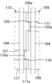
以下、本発明に係るクラッチ装置の一実施形態について図面を参照しながら説明する。図1は、本発明に係るクラッチ装置100の全体構成の概略を示す断面図である。なお、本明細書において参照する各図は、本発明の理解を容易にするために一部の構成要素を誇張して表わすなど模式的に表している。このため、各構成要素間の寸法や比率などは異なっていることがある。このクラッチ装置100は、二輪自動車(オートバイ)における原動機であるエンジン(図示せず)の駆動力を被動体である車輪(図示せず)に伝達および遮断するための機械装置であり、同エンジンと変速機(トランスミッション)(図示せず)との間に配置されるものである。
DESCRIPTION OF THE PREFERRED EMBODIMENTS An embodiment of a clutch device according to the present invention will be described below with reference to the drawings. FIG. 1 is a sectional view schematically showing the overall configuration of a
(クラッチ装置100の構成)
クラッチ装置100は、クラッチハウジング101を備えている。クラッチハウジング101は、フリクションプレート103を保持するとともにこのフリクションプレート103にエンジンからの駆動力を伝達するための部品であり、アルミニウム合金材を有底円筒状に成形して構成されている。より具体的には、クラッチハウジング101の筒状部には、内歯歯車状のスプラインが形成されており、このスプラインに複数枚(本実施形態においては5枚)のフリクションプレート103がクラッチハウジング101の軸線方向に沿って変位可能、かつ同クラッチハウジング101と一体回転可能な状態でスプライン嵌合して保持されている。
(Configuration of clutch device 100)
The
このクラッチハウジング101は、図示左側側面がトルクダンパ(図示せず)を介してリベット101aによって入力ギア102に取り付けられている。入力ギア102は、エンジンの駆動により回転駆動する図示しない駆動ギアと噛合って回転駆動する歯車部品であり、軸受102aを介して後述するシャフト112に回転自在に支持されている。すなわち、クラッチハウジング101は、シャフト112と同心位置でシャフト112と独立して入力ギア102と一体的に回転駆動する。
The left side of the
フリクションプレート103は、クラッチプレート104に押し当てられる平板環状の部品であり、アルミニウム材からなる薄板材を環状に打ち抜いて成形されている。これらのフリクションプレート103における各両側面(表裏面)には、図示しない複数の紙片からなる摩擦材が貼り付けられているとともに各摩擦材間に図示しない油溝が形成されて構成されている。また、これらのフリクションプレート103は、それぞれ同じ大きさおよび形状に形成されている。
The
クラッチハウジング101の内側には、複数枚(本実施形態においては4枚)のクラッチプレート104が前記フリクションプレート103で挟まれた状態でセンタークラッチ105およびプレッシャークラッチ113にそれぞれ保持されている。
Inside the
クラッチプレート104は、前記フリクションプレート103に押し当てられる平板環状の部品であり、SPCC(冷間圧延鋼板)材からなる薄板材を環状に打ち抜いて成形されている。これらのクラッチプレート104における各両側面(表裏面)には、クラッチオイルを保持するための深さ数μm~数十μmの図示しない油溝が形成されているとともに、耐摩耗性を向上させる目的で表面硬化処理がそれぞれ施されている。
The
また、各クラッチプレート104の内周部には、センタークラッチ105に形成されたセンター側嵌合部108およびプレッシャークラッチ113に形成されたプレッシャー側嵌合部117にそれぞれスプライン嵌合する内歯歯車状のスプラインがそれぞれ形成されている。これらのクラッチプレート104は、それぞれ同じ大きさおよび形状に形成されている。なお、摩擦材は、前記フリクションプレート103に代えてクラッチプレート104に設けてもよい。
Further, the inner circumferential portion of each
センタークラッチ105は、図2に示すように、前記クラッチプレート104およびプレッシャークラッチ113をそれぞれ保持するとともにエンジンの駆動力を変速機側に伝達するための部品であり、アルミニウム合金材を略円筒状に成形して構成されている。より具体的には、センタークラッチ105は、主として、接続部105a、中間部105bおよびプレート保持部105cを一体的に形成して構成されている。
As shown in FIG. 2, the
接続部105aは、プレッシャークラッチ113を保持しつつシャフト112に接続される部分であり、円筒状に形成されている。この接続部105aの内周面には、センタークラッチ105の軸線方向に沿って内歯歯車状のスプラインが形成されており、このスプラインにシャフト112がスプライン嵌合している。すなわち、センタークラッチ105は、クラッチハウジング101およびシャフト112と同心位置でシャフト112とともに一体的に回転する。
The connecting
中間部105bは、接続部105aとプレート保持部105cとの間に形成された部分であり、円周状に配置された3つのセンター側カム部106の間に3つの支柱貫通孔107がそれぞれ形成されて構成されている。3つのセンター側カム部106は、センター側アシストカム面106aおよびセンター側スリッパカム面106bを形成する凸状の部分であり、センタークラッチ105の周方向に沿って延びて形成されている。この場合、3つのセンター側カム部106は、センタークラッチ105の周方向に沿って均等に形成されている。そして、各センター側カム部106におけるセンタークラッチ105の周方向の両端部には、センター側アシストカム面106aおよびセンター側スリッパカム面106bがそれぞれ形成されている。
The
各センター側アシストカム面106aは、後述するプレッシャー側アシストカム面114aと協働してフリクションプレート103とクラッチプレート104との圧接力を増強するアシスト力を生じさせるための部分であり、センタークラッチ105の円周方向に沿って徐々にプレッシャークラッチ113側に張り出す傾斜面でそれぞれ構成されている。
Each center side assist
各センター側スリッパカム面106bは、後述するプレッシャー側スリッパカム面114bと協働してフリクションプレート103とクラッチプレート104とを早期に離隔させて半クラッチ状態に移行させるための部分であり、センター側アシストカム面106aとは周方向の反対側にセンター側アシストカム面106aと同じ方向に傾斜する傾斜面でそれぞれ構成されている。ここで、半クラッチ状態とは、クラッチ装置100におけるフリクションプレート103とクラッチプレート104とが完全に密着する前の状態においてエンジンの駆動力の一部が駆動輪側に伝達される不完全な伝達状態のことである。
Each center-side
3つの支柱貫通孔107は、後述する3つの筒状支柱115をそれぞれ貫通させるための貫通孔である。これら3つの支柱貫通孔107は、前記3つのセンター側カム部106の間の位置にセンタークラッチ105の周方向に沿って均等に形成されている。
The three pillar through-
プレート保持部105cは、前記複数枚のクラッチプレート104の一部を保持する部分であり、円筒状に形成されるとともにこの円筒状に形成された部分の端部がフランジ状に張り出して形成されている。このプレート保持部105cにおける前記円筒状に形成された部分の外周面には、センター側嵌合部108が形成されている。
The
センター側嵌合部108は、クラッチプレート104を、フリクションプレート103を挟んだ状態でセンタークラッチ105の軸線方向に沿って変位可能、かつ同センタークラッチ105と一体回転可能な状態保持する部分であり、外歯歯車状のスプラインで構成されている。また、センター側嵌合部108は、このセンター側嵌合部108を構成するスプラインの一部にセンター側突出歯110およびセンター側逃げ部111がそれぞれ形成されているとともに、後述するプレッシャー側嵌合部117に対向するセンター側端面108aにおけるセンター側突出歯110を除く部分、すなわち、スプライン歯よりも内周部分が凹凸のない平らに形成されている。
The center side
センター側突出歯110は、図3に示すように、クラッチプレート104および/またはフリクションプレート103の脱落を防止するための部分であり、センター側嵌合部108を構成するスプライン歯の一つがプレッシャークラッチ113におけるプレッシャー側嵌合部117のプレッシャー側逃げ部121上に達する長さに延びて形成されている。このセンター側突出歯110は、前記3つのセンター側カム部106に対してそれぞれセンタークラッチ105の径方向外側に隣接する位置に形成されている。すなわち、センター側突出歯110は、センタークラッチ105の周方向に沿って均等配置で3つ設けられている。
As shown in FIG. 3, the center
これらの各センター側突出歯110は、先端部110aが後述するプレッシャー側突出歯120の先端部120aに対して、センタークラッチ105に対してプレッシャークラッチ113が最も離隔した際にセンタークラッチ105およびプレッシャークラッチ113の周方向上で軸方向にクラッチプレート104の厚さ未満の幅で離隔する長さに形成されている。また、各センター側突出歯110は、センター側嵌合部108から突出する部分がプレート保持部105c側から先端部110aに向かって歯厚が僅かに細くなるように形成されている。
Each of these center-
センター側逃げ部111は、後述するプレッシャー側突出歯120の物理的干渉を防止するための部分であり、センター側嵌合部108を構成するスプライン歯の一つが省略されて曲面で構成されている。より具体的には、センター側逃げ部111は、プレッシャー側突出歯120が位置するセンター側嵌合部108上の一つのスプライン歯が省略されるとともに、この省略されたスプライン歯に対して周方向の両側にそれぞれ隣接する2つの歯底と面一に直接繋がった凹凸のない平らな円弧面で構成されている。したがって、センター側逃げ部111は、3つのプレッシャー側突出歯120に対応してセンタークラッチ105の周方向に沿って均等配置で形成されている。この場合、センター側逃げ部111は、前記した3つのセンター側突出歯110の各間に均等な間隔で形成されている。
The center
シャフト112は、中空状に形成された軸体であり、一方(図示右側)の端部側が円筒状の軸受102aを介して入力ギア102およびクラッチハウジング101を回転自在に支持するとともに、前記スプライン嵌合するセンタークラッチ105をナット112aを介して固定的に支持する。このシャフト112における他方(図示左側)の端部は、二輪自動車における図示しない変速機に連結されている。すなわち、シャフト112は、本発明における従動軸に相当する。
The
プレッシャークラッチ113は、図1に示すように、フリクションプレート103を押圧することによってこのフリクションプレート103とクラッチプレート104とを互いに密着させるための部品であり、アルミニウム合金材をクラッチプレート104の外径と略同じ大きさの外径の略円盤状に成形して構成されている。より具体的には、プレッシャークラッチ113は、図4に示すように、主として、内側円盤部113aおよびプレート保持部113bを一体的に形成して構成されている。
As shown in FIG. 1, the
内側円盤部113aは、円周状に配置された3つのプレッシャー側カム部114の間に3つの筒状支柱115がそれぞれ有してセンタークラッチ105における接続部105aの外周面上に摺動自在な状態で嵌合している。すなわち、プレッシャークラッチ113は、クラッチハウジング101、センタークラッチ105およびシャフト112と同心位置でセンタークラッチ105およびシャフト112とは独立して回転可能に設けられている。
The
3つのプレッシャー側カム部114は、プレッシャー側アシストカム面114aおよびプレッシャー側スリッパカム面114bを形成する凸状の部分であり、プレッシャークラッチ113の周方向に沿って延びて形成されている。この場合、3つのプレッシャー側カム部114は、プレッシャークラッチ113の周方向に沿って均等に形成されている。そして、各プレッシャー側カム部114におけるプレッシャークラッチ113の周方向の両端部には、プレッシャー側アシストカム面114aおよびプレッシャー側スリッパカム面114bがそれぞれ形成されている。
The three pressure
各プレッシャー側アシストカム面114aは、前記センタークラッチ105のセンター側アシストカム面106a上を摺動する部分であり、プレッシャークラッチ113の円周方向に沿って徐々にセンタークラッチ105側に張り出す傾斜面で構成されている。すなわち、センター側アシストカム面106aとプレッシャー側アシストカム面114aとでアシスト機構が構成されている。そして、このアシスト機構によって発生させるアシスト力によって容量(弾性係数)の低いクラッチスプリング116cを用いることができる。
Each pressure side assist
各プレッシャー側スリッパカム面114bは、前記センター側スリッパカム面106b上を摺動する部分であり、プレッシャー側アシストカム面114aとは周方向の反対側にプレッシャー側アシストカム面114aと同じ方向に延びる傾斜面でそれぞれ構成されている。すなわち、センター側スリッパカム面106bとプレッシャー側スリッパカム面114bとでスリッパ機構が構成されている。
Each pressure-side
3つの筒状支柱115は、リフタープレート116aを支持するためにセンタークラッチ105の軸方向に柱状に延びた円筒状の部分であり、その内周部に取付ボルト116bがネジ嵌合する雌ネジが形成されている。これら3つの筒状支柱115は、プレッシャークラッチ113の周方向に沿って均等に形成されている。
The three
リフタープレート116aは、クラッチスプリング116cをセンタークラッチ105の中間部105bとで挟むための部品であり、金属製の板状体で構成されている。このリフタープレート116aの中央部には、ベアリングを介してレリーズピン116dが設けられている。
The
クラッチスプリング116cは、プレッシャークラッチ113をセンタークラッチ105側に押圧することによってプレッシャークラッチ113のプレート保持部113bをフリクションプレート103に押圧するための弾性体であり、ばね鋼を螺旋状に巻いたコイルスプリングによって構成されている。このクラッチスプリング116cは、3つの筒状支柱115の各間にそれぞれ配置されている。
The
レリーズピン116dは、クラッチ装置100の回転駆動力の伝達状態を切断状態とする際にリフタープレート116aを押圧するための棒状部品であり、一方(図示右側)の端部が図示しないクラッチレリーズ機構に接続されている。ここで、クラッチレリーズ機構とは、クラッチ装置100が搭載される自走式車両の運転者のクラッチ操作レバー(図示しない)の操作によってレリーズピン116dをシャフト112側に押圧する機械装置である。
The
プレート保持部113bは、前記複数枚のクラッチプレート104の他の一部を保持する部分であり、円筒状に形成されるとともにこの円筒状に形成された部分の端部がフランジ状に張り出して形成されている。このプレート保持部113bにおける前記円筒状に形成された部分の外周面には、プレッシャー側嵌合部117が形成されている。
The
プレッシャー側嵌合部117は、クラッチプレート104を、フリクションプレート103を挟んだ状態でプレッシャークラッチ113の軸線方向に沿って変位可能、かつ同プレッシャークラッチ113と一体回転可能な状態保持する部分であり、外歯歯車状のスプラインで構成されている。
The pressure side
この場合、プレッシャー側嵌合部117を構成するスプラインは、センター側嵌合部108を構成するスプラインと同じ歯先円、歯底円および歯厚で形成されているとともに、センター側嵌合部108を構成するスプライン歯よりも短い歯幅で形成されている。この場合、プレッシャークラッチ113は、前記センター側嵌合部を構成するスプラインに対してプレッシャー側嵌合部117を構成するスプラインの位相がずれた位置に設けられる。また、プレッシャー側嵌合部117は、センター側嵌合部108に対向するプレッシャー側端面117aが凹凸のない平らに形成されているとともに、プレッシャー側嵌合部117を構成するスプラインの一部にプレッシャー側突出歯120およびプレッシャー側逃げ部121がそれぞれ形成されている。
In this case, the spline forming the pressure side
プレッシャー側突出歯120は、図3に示すように、クラッチプレート104および/またはフリクションプレート103の脱落を防止するための部分であり、プレッシャー側嵌合部117を構成するスプライン歯の一つがセンタークラッチ105におけるセンター側嵌合部108のセンター側逃げ部111上に達する長さに延びて形成されている。このプレッシャー側突出歯120は、前記3つのプレッシャー側カム部114に対してそれぞれプレッシャークラッチ113の径方向外側に隣接する位置に形成されている。すなわち、プレッシャー側突出歯120は、プレッシャークラッチ113の周方向に沿って均等配置で3つ設けられている。
As shown in FIG. 3, the pressure
これらの各プレッシャー側突出歯120は、先端部120aがセンター側突出歯110の先端部110aに対して、プレッシャークラッチ113がセンタークラッチ105に対して最も離隔した際にセンタークラッチ105およびプレッシャークラッチ113の周方向上で軸方向にクラッチプレート104の厚さ未満の幅で離隔する長さに形成されている。また、各プレッシャー側突出歯120は、プレッシャー側嵌合部117から突出する部分がプレート保持部113b側から先端部120aに向かって歯厚が僅かに細くなるように形成されている。
Each of these pressure-
プレッシャー側逃げ部121は、前記センター側突出歯110の物理的干渉を防止するための部分であり、プレッシャー側嵌合部117を構成するスプライン歯の一つが省略されて曲面で構成されている。より具体的には、プレッシャー側逃げ部121は、センター側突出歯110が位置するプレッシャー側嵌合部117上の一つのスプライン歯が省略されるとともに、この省略されたスプライン歯に対して周方向の両側にそれぞれ隣接する2つの歯底と面一に直接繋がった凹凸のない平らな円弧面で構成されている。したがって、プレッシャー側逃げ部121は、3つのセンター側突出歯110に対応してプレッシャークラッチ113の周方向に沿って均等配置で形成されている。
The pressure
そして、このクラッチ装置100内には、所定量のクラッチオイル(図示しない)が充填されている。クラッチオイルは、主として、フリクションプレート103とクラッチプレート104との間に供給されてこれらの間で生じる摩擦熱の吸収や摩擦材の摩耗を防止する。すなわち、このクラッチ装置100は、所謂湿式多板摩擦クラッチ装置である。
This
(クラッチ装置100の作動)
次に、上記のように構成したクラッチ装置100の作動について説明する。このクラッチ装置100は、前記したように、車両におけるエンジンと変速機との間に配置されるものであり、車両の運転者によるクラッチ操作レバーの操作によってエンジンの駆動力の変速機への伝達および遮断を行なう。
(Operation of clutch device 100)
Next, the operation of the
具体的には、クラッチ装置100は、図1に示すように、車両の運転者(図示せず)がクラッチ操作レバー(図示せず)を操作しない場合においては、クラッチレリーズ機構(図示せず)がレリーズピン116dを押圧しないため、プレッシャークラッチ113がクラッチスプリング116cの弾性力によってフリクションプレート103を押圧する。これにより、センタークラッチ105は、フリクションプレート103とクラッチプレート104とが互いに押し当てられて摩擦連結された状態となって回転駆動する。すなわち、原動機の回転駆動力がセンタークラッチ105に伝達されてシャフト112が回転駆動する。なお、この場合、プレッシャークラッチ113は、アシスト機構によって強い力でセンタークラッチ105に押し付けられている。
Specifically, as shown in FIG. 1, the
このようなクラッチON状態においては、センタークラッチ105におけるプレート保持部105cに形成されたセンター側突出歯110は、図5に示すように、プレッシャークラッチ113におけるプレッシャー側嵌合部117に形成されたプレッシャー側逃げ部121上に位置して互いに重なっている。また、プレッシャークラッチ113におけるプレート保持部113bに形成されたプレッシャー側突出歯120は、センタークラッチ105におけるセンター側嵌合部108に形成されたセンター側逃げ部111上に位置して互いに重なっている。このため、センター側嵌合部108とプレッシャー側嵌合部117との境界部分に存在するフリクションプレート103および/またはクラッチプレート104は、センター側突出歯110およびプレッシャー側突出歯120によってプレート保持部105c,113bからそれぞれ脱落することはない。
In such a clutch ON state, the center
また、クラッチON状態においては、運転者による変速機に対するシフトダウン操作などによってエンジン側の回転数よりも駆動輪側の回転数が上回った場合には、シャフト112の回転数が入力ギア102の回転数を上回ってクラッチ装置100にバックトルクが作用することがある。この場合、クラッチ装置100は、センタークラッチ105に形成されたセンター側スリッパカム面106bにプレッシャークラッチ113に形成されたプレッシャー側スリッパカム面114bが乗り上げるカム作用によってプレッシャークラッチ113がセンタークラッチ105に対して相対回転しながら離隔する方向に変位して押圧力が急激に弱まるスリッパ機能が作用する。
In addition, in the clutch ON state, if the rotation speed of the driving wheels exceeds the rotation speed of the engine due to a downshift operation of the transmission by the driver, etc., the rotation speed of the
このスリッパ機能が作用した場合において、センター側突出歯110は、プレッシャークラッチ113に対して相対的に回転変位するが、プレッシャークラッチ113のプレッシャー側嵌合部117にはプレッシャー側逃げ部121が隣接する歯底と面一で一体的に繋がって形成されているため、プレッシャー側嵌合部117を構成するスプライン歯に衝突するなど物理的に干渉することはない。また、プレッシャー側突出歯120についてもセンター側突出歯110と同様に、センタークラッチ105のセンター側嵌合部108にはセンター側逃げ部111が隣接する歯底と面一で一体的に繋がって形成されているため、センター側嵌合部108を構成するスプライン歯に衝突するなど物理的に干渉することはない。
When this slipper function is activated, the center-
一方、クラッチ装置100は、図6および図7にそれぞれに示すように、車両の運転者がクラッチ操作レバーを操作した場合においては、クラッチレリーズ機構(図示せず)がレリーズピン116dを押圧するため、プレッシャークラッチ113がクラッチスプリング116cの弾性力に抗してセンタークラッチ105から離隔する方向に変位する。これにより、センタークラッチ105は、フリクションプレート103とクラッチプレート104との摩擦連結が解消された状態となるため、回転駆動が減衰または回転駆動が停止する状態となる。すなわち、原動機の回転駆動力がセンタークラッチ105に対して遮断される。
On the other hand, as shown in FIGS. 6 and 7, in the
そして、このクラッチOFF状態においては、図8に示すように、センタークラッチ105におけるプレート保持部105cに形成されたセンター側突出歯110は、プレッシャークラッチ113におけるプレッシャー側嵌合部117に形成されたプレッシャー側逃げ部121上に重ならない離隔した位置でかつセンター側嵌合部108のセンター側端面108aとプレッシャー側嵌合部117のプレッシャー側端面117aとの間の離隔した隙間上に位置する。このため、センター側嵌合部108とプレッシャー側嵌合部117との境界部分に存在していたフリクションプレート103および/またはクラッチプレート104は、センター側突出歯110によってプレート保持部105c,113bから脱落することはない。
In this clutch OFF state, as shown in FIG. It is located at a spaced apart position that does not overlap with the
また、プレッシャークラッチ113におけるプレート保持部113bに形成されたプレッシャー側突出歯120は、センタークラッチ105におけるセンター側嵌合部108に形成されたセンター側逃げ部111上に重ならない離隔した位置でかつプレッシャー側嵌合部117のプレッシャー側端面117aとセンター側嵌合部108のセンター側端面108aとの間の離隔した隙間上に位置する。このため、プレッシャー側嵌合部117とセンター側嵌合部108との境界部分に存在していたフリクションプレート103および/またはクラッチプレート104は、プレッシャー側突出歯120によってプレート保持部105c,113bから脱落することはない。
Further, the pressure-
この場合、センター側突出歯110とプレッシャー側突出歯120とは、図8に示すように、互いに異なる周方向上の位置に位置しているが、センター側突出歯110の先端部110aの周方向の軌跡とプレッシャー側突出歯120の先端部120aの周方向の軌跡との間の隙間Sは、クラッチプレート104の厚さ未満の幅で形成されている。これにより、クラッチ装置100は、センター側突出歯110およびプレッシャー側突出歯120にそれぞれ嵌合するクラッチプレート104の脱落を防止しつつセンター側突出歯110上およびプレッシャー側突出歯120上での軸方向への変位可能範囲を最大化することができるため、クラッチオイルの流通性を向上できるとともに引き摺りトルクを低減することができる。
In this case, as shown in FIG. 8, the center
なお、図6は、クラッチOFF状態において、フリクションプレート103およびクラッチプレート104がセンタークラッチ105側に最大の枚数で偏った場合の状態を示している。また、図7は、クラッチOFF状態において、フリクションプレート103およびクラッチプレート104がプレッシャークラッチ113側に最大の枚数で偏った場合の状態を示している。すなわち、本発明に係るクラッチ装置100は、クラッチOFF時において、フリクションプレート103およびクラッチプレート104がセンタークラッチ105側またはプレッシャークラッチ113側に偏ってしまった場合においてもプレート保持部105c,113bから脱落することはない。
Note that FIG. 6 shows a state in which the maximum number of
また、図5および図8は、センター側突出歯110とプレッシャー側突出歯120との位置関係を明確するための模式図であり、2つのクラッチプレート104の間に配置されるフリクションプレート103の図示を省略している。
5 and 8 are schematic diagrams for clarifying the positional relationship between the center
この後、クラッチ装置100は、再び、車両の運転者によるクラッチ操作レバーの操作によってクラッチON状態に移行した場合であっても、センター側突出歯110がプレッシャー側嵌合部117に物理的に干渉することがないとともに、センター側嵌合部108とプレッシャー側嵌合部117との境界部分に存在していたフリクションプレート103および/またはクラッチプレート104はセンター側突出歯110およびプレッシャー側突出歯120によってプレート保持部105c,113bから脱落することはない。
Thereafter, even if the
上記作動説明からも理解できるように、上記実施形態によれば、クラッチ装置100は、センタークラッチ105およびプレッシャークラッチ113における互いに対向し合う各端面であるセンター側端面108aおよびプレッシャー側端面117aがそれぞれ凹凸なく平らに形成されてプレッシャー側突出歯120およびセンター側突出歯110のみがセンター側逃げ部111側およびプレッシャー側逃げ部121側にそれぞれ張り出して形成されているため、フリクションプレート103および/またはクラッチプレート104の脱落を防止しつつクラッチオイルの流れを阻害することを抑えて流通性を向上させることができる。
As can be understood from the above description of operation, in the
さらに、本発明の実施にあたっては、上記実施形態に限定されるものではなく、本発明の目的を逸脱しない限りにおいて種々の変更が可能である。なお、下記に示す各変形例においては、上記実施形態におけるクラッチ装置100と同様の構成部分にはクラッチ装置100に付した符号に同一の符号を付して、その説明は省略する。
Furthermore, the implementation of the present invention is not limited to the above-described embodiments, and various changes can be made without departing from the purpose of the present invention. In addition, in each modification shown below, the same code|symbol is attached|subjected to the code|symbol attached to the
例えば、上記実施形態においては、プレッシャー側嵌合部117を構成するスプラインは、センター側嵌合部108を構成するスプラインと同じ歯先円、歯底円および歯厚で形成されているとともに、センター側嵌合部108を構成するスプライン歯よりも短い歯幅で形成されている。しかし、センター側嵌合部108を構成するスプラインとプレッシャー側嵌合部117を構成するスプラインは、少なくとも互いに同じ歯先円で形成されて互いに対向配置されていればよい。これにより、複数のクラッチプレート104を全て同じ大きさおよび形状で構成することができる。一方で、プレッシャー側嵌合部117を構成するスプラインは、例えば、センター側嵌合部108を構成するスプラインよりも小さい歯底円または長い歯厚で形成することもできる。
For example, in the above embodiment, the spline forming the pressure side
また、上記実施形態においては、センター側突出歯110およびプレッシャー側突出歯120は、センター側嵌合部108およびプレッシャー側嵌合部117の各周方向に沿って均等配置で3つ設けた。しかし、センター側突出歯110およびプレッシャー側突出歯120は、センター側嵌合部108およびプレッシャー側嵌合部117に少なくとも1つずつ設けられていればよく、2つ、3つまたは4つ以上設けられていてもよい。また、センター側突出歯110とプレッシャー側突出歯120とは、必ずしも交互に設ける必要もないとともに周方向に沿って均等な間隔で設ける必要もない。
Further, in the embodiment described above, three center-
また、上記実施形態においては、センター側突出歯110およびプレッシャー側突出歯120は、センター側突出歯110の先端部110aの周方向の軌跡とプレッシャー側突出歯120の先端部120aの周方向の軌跡との間の隙間Sがクラッチプレート104の厚さ未満の幅で形成される長さにそれぞれ形成されている。しかし、センター側突出歯110およびプレッシャー側突出歯120は、クラッチOFF時において互いの先端部110aと先端部120aとの間がクラッチプレート104の厚さ未満の隙間になる長さに形成されていればよい。
Further, in the above embodiment, the center
したがって、センター側突出歯110およびプレッシャー側突出歯120は、例えば、図9に示すように、センタークラッチ105に対してプレッシャークラッチ113が最も離隔した場合においてセンタークラッチ105およびプレッシャークラッチ113の周方向上で軸方向に互いに重なるラップ部Rが形成される長さに形成することができる。これによれば、クラッチ装置100は、センター側突出歯110およびプレッシャー側突出歯120に対してフリクションプレート103および/またはクラッチプレート104が完全に嵌合した状態を常に維持することができるため、フリクションプレート103および/またはクラッチプレート104を安定的に保持することができる。
Therefore, as shown in FIG. 9, for example, the center
また、センター側突出歯110およびプレッシャー側突出歯120は、例えば、図10に示すように、センタークラッチ105に対してプレッシャークラッチ113が最も離隔した場合においてセンタークラッチ105およびプレッシャークラッチ113の周方向上で軸方向に先端部110aと先端部120aとが面一になる長さに形成することができる。これによれば、クラッチ装置100は、センター側突出歯110およびプレッシャー側突出歯120に対してフリクションプレート103および/またはクラッチプレート104が完全に嵌合した状態を常に維持することができるとともにセンター側突出歯110上およびプレッシャー側突出歯120上での軸方向への変位可能範囲を最大化することができるため、クラッチオイルの流通性を向上できるとともに引き摺りトルクを低減することができる。
Further, the center
また、図9および図10は、センター側突出歯110とプレッシャー側突出歯120との位置関係を明確するための模式図であり、2つのクラッチプレート104の間に配置されるフリクションプレート103の図示を省略している。
9 and 10 are schematic diagrams for clarifying the positional relationship between the center
また、上記実施形態においては、センター側突出歯110およびプレッシャー側突出歯120は、それぞれ先端部110a,120aに向かって歯厚が細くなるように形成した。これにより、クラッチ装置100は、クラッチOFFは当然、クラッチON時におけるクラッチオイルの流通性をより向上させることができる。この場合、センター側突出歯110およびプレッシャー側突出歯120は、歯厚に代えてまたは加えてそれぞれ先端部110a,120aに向かって全歯たけが低くなるように形成することができる。すなわち、センター側突出歯110およびプレッシャー側突出歯120は、それぞれ先端部110a,120aに向かって外形が細くなるように形成することができる。しかし、センター側突出歯110およびプレッシャー側突出歯120は、それぞれ歯幅方向に同じ太さの外形で形成されていてもよい。
Further, in the above embodiment, the center
また、上記実施形態においては、センター側逃げ部111およびプレッシャー側逃げ部121は、周方向に隣接する歯底と面一で構成した。しかし、センター側逃げ部111およびプレッシャー側逃げ部121は、プレッシャー側突出歯120およびセンター側突出歯110に衝突したり突き当たったりするなど物理的に干渉しないように形成されていればよいため、周方向に隣接する歯底と同じ高さ以下(換言すれば、歯底の仮想延長面に対して面一以下)に形成されていればよい。
Further, in the embodiment described above, the center
また、上記実施形態においては、センター側逃げ部111およびプレッシャー側逃げ部121は、センター側嵌合部108およびプレッシャー側嵌合部117を構成するスプライン歯の歯幅方向の全域に亘って形成した。しかし、センター側逃げ部111およびプレッシャー側逃げ部121は、プレッシャー側突出歯120およびセンター側突出歯110に物理的に干渉しないように形成されていればよいため、センター側逃げ部111およびプレッシャー側嵌合部117を構成するスプライン歯の歯幅方向の一部にのみ形成されるとともに他の一部にスプライン歯が形成されるように構成してもよい。
Further, in the embodiment described above, the center
また、上記実施形態においては、クラッチ装置100は、アシスト機構およびスリッパ機構を備えて構成した。しかし、クラッチ装置100は、アシスト機構およびスリッパ機構のうちの少なくとも一方を備えない構成であってもよい。
Further, in the embodiment described above, the
また、上記実施形態においては、プレッシャークラッチ113は、フリクションプレート103を押圧するように構成されている。しかし、プレッシャークラッチ113は、フリクションプレート103とクラッチプレート104とを互いに密着させるようにフリクションプレート103またはクラッチプレート104を押圧するように構成されていればよい。すなわち、プレッシャークラッチ113は、クラッチプレート104を押圧するように構成してよい。例えば、上記実施形態におけるフリクションプレート103とクラッチプレート104の配置位置を入れ替えてプレッシャークラッチ113がクラッチプレート104を押圧するように構成することもできる。
Further, in the embodiment described above, the
S…クラッチOFF時におけるセンター側突出歯110の先端部110aとプレッシャー側突出歯120の先端部120aとの間の隙間、R…クラッチOFF時におけるセンター側突出歯110の先端部110aとプレッシャー側突出歯120の先端部120aとが軸方向に沿って重なるラップ部、
100…クラッチ装置、101…クラッチハウジング、101a…リベット、102…入力ギア、102a…軸受、103…フリクションプレート、104…クラッチプレート、105…センタークラッチ、105a…接続部、105b…中間部、105c…プレート保持部、106…センター側カム部、106a…センター側アシストカム面、106b…センター側スリッパカム面、107…支柱貫通孔、108…センター側嵌合部、108a…センター側端面、
110…センター側突出歯、110a…先端部、111…センター側逃げ部、112…シャフト、112a…ナット、113…プレッシャークラッチ、113a…内側円盤部、113b…プレート保持部、114…プレッシャー側カム部、114a…プレッシャー側アシストカム面、114b…プレッシャー側スリッパカム面、115…筒状支柱、116a…リフタープレート、116b…取付ボルト、116c…クラッチスプリング、116d…レリーズピン、117…プレッシャー側嵌合部、117a…プレッシャー側端面、
120…プレッシャー側突出歯、120a…先端部、121…プレッシャー側逃げ部。
S...Gap between the
DESCRIPTION OF
DESCRIPTION OF
120... Pressure side protruding tooth, 120a... Tip part, 121... Pressure side escape part.
Claims (5)
前記原動軸の回転駆動によって回転駆動する複数のフリクションプレートにそれぞれ対向配置される環状の平板で構成されるとともに同平板の内周部に内歯を有した複数のクラッチプレートと、
前記クラッチプレートの前記内歯に嵌合する外歯を有して前記従動軸に連結されるセンタークラッチと、
前記クラッチプレートの前記内歯に嵌合する外歯を有して前記センタークラッチに対して接近および離隔する方向にそれぞれ変位可能に隣接配置されて前記フリクションプレートまたは前記クラッチプレートを押圧するプレッシャークラッチとを備え、
前記センタークラッチおよび前記プレッシャークラッチは、
互いに対向し合う各端面が凹凸なく平らに形成されるとともに各前記外歯が互いに同じ歯先円に形成されており、かつ
前記センタークラッチおよび前記プレッシャークラッチにおける各前記外歯における歯を部分的に省略したセンター側逃げ部およびプレッシャー側逃げ部と、
各前記外歯のうちの少なくとも1つの歯が前記センター側逃げ部および前記プレッシャー側逃げ部にそれぞれ張り出して延びるプレッシャー側突出歯およびセンター側突出歯とをそれぞれ備え、
前記プレッシャー側突出歯および前記センター側突出歯は、
前記センタークラッチに対して前記プレッシャークラッチが最も離隔した際に、前記プレッシャー側逃げ部上および前記センター側逃げ部上にそれぞれ重ならない位置でかつ前記各端面であるセンター側端面とプレッシャー側端面との間の離隔した隙間上にそれぞれ位置した状態で、前記センタークラッチおよび前記プレッシャークラッチの周方向で軸方向に互いに重なる長さに形成されていることを特徴とするクラッチ装置。 In a clutch device that transmits and interrupts rotational driving force of a driving shaft to a driven shaft,
a plurality of clutch plates each comprising an annular flat plate disposed opposite to a plurality of friction plates rotationally driven by the rotational drive of the driving shaft and having internal teeth on an inner peripheral portion of the flat plate;
a center clutch connected to the driven shaft and having external teeth that fit into the internal teeth of the clutch plate;
a pressure clutch that has external teeth that fit into the internal teeth of the clutch plate and is disposed adjacent to the center clutch so as to be movable toward and away from the center clutch, and presses the friction plate or the clutch plate; Equipped with
The center clutch and the pressure clutch are
The end surfaces facing each other are formed flat without any irregularities, and each of the external teeth is formed to have the same tip circle, and the teeth of each of the external teeth of the center clutch and the pressure clutch are partially The omitted center side relief part and pressure side relief part,
At least one tooth of each of the external teeth includes a pressure-side protruding tooth and a center-side protruding tooth that extend and extend into the center-side relief part and the pressure-side relief part, respectively ,
The pressure side protruding teeth and the center side protruding teeth are
When the pressure clutch is farthest away from the center clutch , the center side end face and the pressure side end face are located at a position that does not overlap with the pressure side relief portion and the center side relief portion, respectively, and where the center side end face and the pressure side end face are the respective end faces. A clutch device characterized in that the center clutch and the pressure clutch are formed to have lengths that overlap each other in the axial direction in the circumferential direction of the center clutch and the pressure clutch, respectively, with the center clutch and the pressure clutch being positioned on a gap spaced apart from each other.
前記原動軸の回転駆動によって回転駆動する複数のフリクションプレートにそれぞれ対向配置される環状の平板で構成されるとともに同平板の内周部に内歯を有した複数のクラッチプレートと、
前記クラッチプレートの前記内歯に嵌合する外歯を有して前記従動軸に連結されるセンタークラッチと、
前記クラッチプレートの前記内歯に嵌合する外歯を有して前記センタークラッチに対して接近および離隔する方向にそれぞれ変位可能に隣接配置されて前記フリクションプレートまたは前記クラッチプレートを押圧するプレッシャークラッチとを備え、
前記センタークラッチおよび前記プレッシャークラッチは、
互いに対向し合う各端面が凹凸なく平らに形成されるとともに各前記外歯が互いに同じ歯先円に形成されており、かつ
前記センタークラッチおよび前記プレッシャークラッチにおける各前記外歯における歯を部分的に省略したセンター側逃げ部およびプレッシャー側逃げ部と、
各前記外歯のうちの少なくとも1つの歯が前記センター側逃げ部および前記プレッシャー側逃げ部にそれぞれ張り出して延びるプレッシャー側突出歯およびセンター側突出歯とをそれぞれ備え、
前記プレッシャー側突出歯および前記センター側突出歯は、
前記センタークラッチに対して前記プレッシャークラッチが最も離隔した際に前記センタークラッチおよび前記プレッシャークラッチの周方向で軸方向に互いの先端部が面一になる長さに形成されていることを特徴とするクラッチ装置。 In a clutch device that transmits and interrupts rotational driving force of a driving shaft to a driven shaft,
a plurality of clutch plates each comprising an annular flat plate disposed opposite to a plurality of friction plates rotationally driven by the rotational drive of the driving shaft and having internal teeth on an inner peripheral portion of the flat plate;
a center clutch connected to the driven shaft and having external teeth that fit into the internal teeth of the clutch plate;
a pressure clutch that has external teeth that fit into the internal teeth of the clutch plate and is disposed adjacent to the center clutch so as to be movable toward and away from the center clutch, and presses the friction plate or the clutch plate; Equipped with
The center clutch and the pressure clutch are
The end surfaces facing each other are formed flat without irregularities, and each of the external teeth is formed to have the same tip circle, and the teeth of each of the external teeth of the center clutch and the pressure clutch are partially The omitted center side relief part and pressure side relief part,
At least one tooth of each of the external teeth includes a pressure-side protruding tooth and a center-side protruding tooth that extend and extend in the center-side relief part and the pressure-side relief part, respectively ,
The pressure side protruding teeth and the center side protruding teeth are
The center clutch and the pressure clutch are formed to such a length that their tip ends are flush with each other in the circumferential direction and the axial direction when the pressure clutch is farthest away from the center clutch. clutch device.
前記原動軸の回転駆動によって回転駆動する複数のフリクションプレートにそれぞれ対向配置される環状の平板で構成されるとともに同平板の内周部に内歯を有した複数のクラッチプレートと、
前記クラッチプレートの前記内歯に嵌合する外歯を有して前記従動軸に連結されるセンタークラッチと、
前記クラッチプレートの前記内歯に嵌合する外歯を有して前記センタークラッチに対して接近および離隔する方向にそれぞれ変位可能に隣接配置されて前記フリクションプレートまたは前記クラッチプレートを押圧するプレッシャークラッチとを備え、
前記センタークラッチおよび前記プレッシャークラッチは、
互いに対向し合う各端面が凹凸なく平らに形成されるとともに各前記外歯が互いに同じ歯先円に形成されており、かつ
前記センタークラッチおよび前記プレッシャークラッチにおける各前記外歯における歯を部分的に省略したセンター側逃げ部およびプレッシャー側逃げ部と、
各前記外歯のうちの少なくとも1つの歯が前記センター側逃げ部および前記プレッシャー側逃げ部にそれぞれ張り出して延びるプレッシャー側突出歯およびセンター側突出歯とをそれぞれ備え、
前記プレッシャー側突出歯および前記センター側突出歯は、
前記センタークラッチに対して前記プレッシャークラッチが最も離隔した際に前記センタークラッチおよび前記プレッシャークラッチの周方向上で軸方向に前記クラッチプレートの厚さ未満の幅で互いの先端部が離隔する長さに形成されていることを特徴とするクラッチ装置。 In a clutch device that transmits and interrupts rotational driving force of a driving shaft to a driven shaft,
a plurality of clutch plates each comprising an annular flat plate disposed opposite to a plurality of friction plates rotationally driven by the rotational drive of the driving shaft and having internal teeth on an inner peripheral portion of the flat plate;
a center clutch connected to the driven shaft and having external teeth that fit into the internal teeth of the clutch plate;
a pressure clutch that has external teeth that fit into the internal teeth of the clutch plate and is disposed adjacent to the center clutch so as to be movable toward and away from the center clutch, and presses the friction plate or the clutch plate; Equipped with
The center clutch and the pressure clutch are
The end surfaces facing each other are formed flat without irregularities, and each of the external teeth is formed to have the same tip circle, and the teeth of each of the external teeth of the center clutch and the pressure clutch are partially The omitted center side relief part and pressure side relief part,
At least one tooth of each of the external teeth includes a pressure-side protruding tooth and a center-side protruding tooth that extend and extend in the center-side relief part and the pressure-side relief part, respectively ,
The pressure side protruding teeth and the center side protruding teeth are
A length such that when the pressure clutch is furthest apart from the center clutch, the tips of the center clutch and the pressure clutch are separated from each other by a width less than the thickness of the clutch plate in the circumferential direction of the center clutch and the pressure clutch. A clutch device characterized in that:
前記原動軸の回転駆動によって回転駆動する複数のフリクションプレートにそれぞれ対向配置される環状の平板で構成されるとともに同平板の内周部に内歯を有した複数のクラッチプレートと、
前記クラッチプレートの前記内歯に嵌合する外歯を有して前記従動軸に連結されるセンタークラッチと、
前記クラッチプレートの前記内歯に嵌合する外歯を有して前記センタークラッチに対して接近および離隔する方向にそれぞれ変位可能に隣接配置されて前記フリクションプレートまたは前記クラッチプレートを押圧するプレッシャークラッチとを備え、
前記センタークラッチおよび前記プレッシャークラッチは、
互いに対向し合う各端面が凹凸なく平らに形成されるとともに各前記外歯が互いに同じ歯先円に形成されており、かつ
前記センタークラッチおよび前記プレッシャークラッチにおける各前記外歯における歯を部分的に省略したセンター側逃げ部およびプレッシャー側逃げ部と、
各前記外歯のうちの少なくとも1つの歯が前記センター側逃げ部および前記プレッシャー側逃げ部にそれぞれ張り出して延びるプレッシャー側突出歯およびセンター側突出歯とをそれぞれ備え、
前記プレッシャー側突出歯および前記センター側突出歯は、
それぞれ先端部に向かって歯厚が細くなるように形成されていることを特徴とするクラッチ装置。 In a clutch device that transmits and interrupts rotational driving force of a driving shaft to a driven shaft,
a plurality of clutch plates each comprising an annular flat plate disposed opposite to a plurality of friction plates rotationally driven by the rotational drive of the driving shaft and having internal teeth on an inner peripheral portion of the flat plate;
a center clutch connected to the driven shaft and having external teeth that fit into the internal teeth of the clutch plate;
a pressure clutch that has external teeth that fit into the internal teeth of the clutch plate and is disposed adjacent to the center clutch so as to be movable toward and away from the center clutch, and presses the friction plate or the clutch plate; Equipped with
The center clutch and the pressure clutch are
The end surfaces facing each other are formed flat without irregularities, and each of the external teeth is formed to have the same tip circle, and the teeth of each of the external teeth of the center clutch and the pressure clutch are partially The omitted center side relief part and pressure side relief part,
At least one tooth of each of the external teeth includes a pressure-side protruding tooth and a center-side protruding tooth that extend and extend into the center-side relief part and the pressure-side relief part, respectively ,
The pressure side protruding teeth and the center side protruding teeth are
A clutch device characterized in that each tooth is formed so that the tooth thickness becomes thinner toward the tip.
前記プレッシャー側突出歯および前記センター側突出歯は、
前記センタークラッチおよび前記プレッシャークラッチの周方向に沿って交互に形成されていることを特徴とするクラッチ装置。
In the clutch device according to any one of claims 1 to 4,
The pressure side protruding teeth and the center side protruding teeth are
A clutch device characterized in that the center clutch and the pressure clutch are formed alternately along the circumferential direction.
Priority Applications (5)
| Application Number | Priority Date | Filing Date | Title |
|---|---|---|---|
| JP2019105822A JP7429484B2 (en) | 2019-06-06 | 2019-06-06 | clutch device |
| TW109113814A TWI846866B (en) | 2019-06-06 | 2020-04-24 | Clutch device |
| PCT/JP2020/021627 WO2020246429A1 (en) | 2019-06-06 | 2020-06-01 | Clutch device |
| CN202080029200.3A CN113811697B (en) | 2019-06-06 | 2020-06-01 | clutch device |
| BR112021021358A BR112021021358A2 (en) | 2019-06-06 | 2020-06-01 | clutch device |
Applications Claiming Priority (1)
| Application Number | Priority Date | Filing Date | Title |
|---|---|---|---|
| JP2019105822A JP7429484B2 (en) | 2019-06-06 | 2019-06-06 | clutch device |
Publications (3)
| Publication Number | Publication Date |
|---|---|
| JP2020200842A JP2020200842A (en) | 2020-12-17 |
| JP2020200842A5 JP2020200842A5 (en) | 2022-06-10 |
| JP7429484B2 true JP7429484B2 (en) | 2024-02-08 |
Family
ID=73652010
Family Applications (1)
| Application Number | Title | Priority Date | Filing Date |
|---|---|---|---|
| JP2019105822A Active JP7429484B2 (en) | 2019-06-06 | 2019-06-06 | clutch device |
Country Status (4)
| Country | Link |
|---|---|
| JP (1) | JP7429484B2 (en) |
| CN (1) | CN113811697B (en) |
| BR (1) | BR112021021358A2 (en) |
| WO (1) | WO2020246429A1 (en) |
Families Citing this family (2)
| Publication number | Priority date | Publication date | Assignee | Title |
|---|---|---|---|---|
| JP2024030129A (en) | 2022-08-23 | 2024-03-07 | 株式会社エクセディ | clutch device |
| JP7196356B1 (en) | 2022-09-06 | 2022-12-26 | 株式会社エフ・シー・シー | Clutch device and motorcycle |
Citations (2)
| Publication number | Priority date | Publication date | Assignee | Title |
|---|---|---|---|---|
| JP2010236653A (en) | 2009-03-31 | 2010-10-21 | Honda Motor Co Ltd | Multiplate disc clutch |
| JP2018204655A (en) | 2017-06-01 | 2018-12-27 | 株式会社エフ・シー・シー | Clutch device |
Family Cites Families (16)
| Publication number | Priority date | Publication date | Assignee | Title |
|---|---|---|---|---|
| JP3071559B2 (en) * | 1992-05-12 | 2000-07-31 | 本田技研工業株式会社 | Method of manufacturing friction plate in multi-plate friction clutch |
| JP4290804B2 (en) * | 1999-03-09 | 2009-07-08 | ユニプレス株式会社 | Clutch drum structure |
| JP2001107979A (en) * | 1999-10-07 | 2001-04-17 | Daihatsu Motor Co Ltd | Multiple disk clutch device |
| JP3669564B2 (en) * | 1999-11-25 | 2005-07-06 | トヨタ自動車株式会社 | Snap ring groove forming device for clutch drum |
| DE10236841A1 (en) * | 2002-08-10 | 2004-02-26 | Sachs Race Engineering Gmbh | Contact force transmission plate for a friction clutch |
| JP2005325993A (en) * | 2004-01-14 | 2005-11-24 | F C C:Kk | Power transmission device |
| JP2006200585A (en) * | 2005-01-18 | 2006-08-03 | Nsk Ltd | Wet multiplate clutch device |
| JP4370350B2 (en) * | 2007-08-20 | 2009-11-25 | 株式会社エクセディ | Motorcycle clutch device |
| JP2011112172A (en) * | 2009-11-27 | 2011-06-09 | Dainatsukusu:Kk | Snap ring drop-prevention mechanism |
| DE102012011819A1 (en) * | 2012-06-14 | 2013-12-19 | Hoerbiger Antriebstechnik Holding Gmbh | Assembly for transmitting high torques in industry shiftable clutches and brakes, has disk carrier ring gear has front sided projections, which are spaced apart in circumferential direction and engaged to receiving groove |
| JP2014224580A (en) * | 2013-05-17 | 2014-12-04 | 株式会社エクセディ | Clutch device for motor cycle |
| JP6735180B2 (en) * | 2016-03-04 | 2020-08-05 | ジーケーエヌ オートモーティブ リミテッド | A cam mechanism and a clutch device using this cam mechanism. |
| JP6819248B2 (en) * | 2016-11-30 | 2021-01-27 | 株式会社ジェイテクト | Driving force transmission device |
| CN110062853B (en) * | 2016-12-15 | 2022-11-15 | 伊顿智能动力有限公司 | Clutch assembly with high repeatability and maintainability |
| JP6553696B2 (en) * | 2017-10-26 | 2019-07-31 | 株式会社エフ・シー・シー | Clutch device |
| JP6691563B2 (en) * | 2018-03-14 | 2020-04-28 | 株式会社エクセディ | Clutch device |
-
2019
- 2019-06-06 JP JP2019105822A patent/JP7429484B2/en active Active
-
2020
- 2020-06-01 BR BR112021021358A patent/BR112021021358A2/en unknown
- 2020-06-01 WO PCT/JP2020/021627 patent/WO2020246429A1/en active Application Filing
- 2020-06-01 CN CN202080029200.3A patent/CN113811697B/en active Active
Patent Citations (2)
| Publication number | Priority date | Publication date | Assignee | Title |
|---|---|---|---|---|
| JP2010236653A (en) | 2009-03-31 | 2010-10-21 | Honda Motor Co Ltd | Multiplate disc clutch |
| JP2018204655A (en) | 2017-06-01 | 2018-12-27 | 株式会社エフ・シー・シー | Clutch device |
Also Published As
| Publication number | Publication date |
|---|---|
| JP2020200842A (en) | 2020-12-17 |
| CN113811697B (en) | 2023-08-22 |
| WO2020246429A1 (en) | 2020-12-10 |
| TW202045834A (en) | 2020-12-16 |
| CN113811697A (en) | 2021-12-17 |
| BR112021021358A2 (en) | 2021-12-14 |
Similar Documents
| Publication | Publication Date | Title |
|---|---|---|
| JP6498722B2 (en) | Clutch device | |
| CN111148917B (en) | Clutch device | |
| JP7231333B2 (en) | clutch device | |
| JP6596180B2 (en) | Clutch device | |
| JP6894792B2 (en) | Power transmission device | |
| JP7429484B2 (en) | clutch device | |
| JP7212193B1 (en) | Clutch device and motorcycle | |
| JP6961427B2 (en) | Power transmission device | |
| JP7403702B1 (en) | clutch device | |
| US11879504B1 (en) | Clutch device and motorcycle | |
| JP7196356B1 (en) | Clutch device and motorcycle | |
| JP7429485B2 (en) | clutch device | |
| TW201837332A (en) | Clutch friction plate and clutch device | |
| TWI846866B (en) | Clutch device | |
| JP7255009B1 (en) | Clutch device and motorcycle | |
| JP7252405B1 (en) | Clutch device and motorcycle | |
| WO2024009761A1 (en) | Clutch device and motorcycle | |
| CN220505630U (en) | Clutch device and motorcycle |
Legal Events
| Date | Code | Title | Description |
|---|---|---|---|
| A521 | Request for written amendment filed |
Free format text: JAPANESE INTERMEDIATE CODE: A523 Effective date: 20220601 |
|
| A621 | Written request for application examination |
Free format text: JAPANESE INTERMEDIATE CODE: A621 Effective date: 20220601 |
|
| A131 | Notification of reasons for refusal |
Free format text: JAPANESE INTERMEDIATE CODE: A131 Effective date: 20230801 |
|
| A521 | Request for written amendment filed |
Free format text: JAPANESE INTERMEDIATE CODE: A523 Effective date: 20230927 |
|
| TRDD | Decision of grant or rejection written | ||
| A01 | Written decision to grant a patent or to grant a registration (utility model) |
Free format text: JAPANESE INTERMEDIATE CODE: A01 Effective date: 20240109 |
|
| A61 | First payment of annual fees (during grant procedure) |
Free format text: JAPANESE INTERMEDIATE CODE: A61 Effective date: 20240124 |
|
| R150 | Certificate of patent or registration of utility model |
Ref document number: 7429484 Country of ref document: JP Free format text: JAPANESE INTERMEDIATE CODE: R150 |