JP6894792B2 - Power transmission device - Google Patents
Power transmission device Download PDFInfo
- Publication number
- JP6894792B2 JP6894792B2 JP2017145838A JP2017145838A JP6894792B2 JP 6894792 B2 JP6894792 B2 JP 6894792B2 JP 2017145838 A JP2017145838 A JP 2017145838A JP 2017145838 A JP2017145838 A JP 2017145838A JP 6894792 B2 JP6894792 B2 JP 6894792B2
- Authority
- JP
- Japan
- Prior art keywords
- clutch
- pressure
- cam
- side clutch
- plate
- Prior art date
- Legal status (The legal status is an assumption and is not a legal conclusion. Google has not performed a legal analysis and makes no representation as to the accuracy of the status listed.)
- Active
Links
Images


Classifications
-
- F—MECHANICAL ENGINEERING; LIGHTING; HEATING; WEAPONS; BLASTING
- F16—ENGINEERING ELEMENTS AND UNITS; GENERAL MEASURES FOR PRODUCING AND MAINTAINING EFFECTIVE FUNCTIONING OF MACHINES OR INSTALLATIONS; THERMAL INSULATION IN GENERAL
- F16D—COUPLINGS FOR TRANSMITTING ROTATION; CLUTCHES; BRAKES
- F16D13/00—Friction clutches
- F16D13/22—Friction clutches with axially-movable clutching members
- F16D13/38—Friction clutches with axially-movable clutching members with flat clutching surfaces, e.g. discs
- F16D13/52—Clutches with multiple lamellae ; Clutches in which three or more axially moveable members are fixed alternately to the shafts to be coupled and are pressed from one side towards an axially-located member
- F16D13/54—Clutches with multiple lamellae ; Clutches in which three or more axially moveable members are fixed alternately to the shafts to be coupled and are pressed from one side towards an axially-located member with means for increasing the effective force between the actuating sleeve or equivalent member and the pressure member
- F16D13/56—Clutches with multiple lamellae ; Clutches in which three or more axially moveable members are fixed alternately to the shafts to be coupled and are pressed from one side towards an axially-located member with means for increasing the effective force between the actuating sleeve or equivalent member and the pressure member in which the clutching pressure is produced by springs only
- F16D2013/565—Clutches with multiple lamellae ; Clutches in which three or more axially moveable members are fixed alternately to the shafts to be coupled and are pressed from one side towards an axially-located member with means for increasing the effective force between the actuating sleeve or equivalent member and the pressure member in which the clutching pressure is produced by springs only with means for releasing the clutch pressure in case of back torque
Landscapes
- Engineering & Computer Science (AREA)
- General Engineering & Computer Science (AREA)
- Mechanical Engineering (AREA)
- Mechanical Operated Clutches (AREA)
- One-Way And Automatic Clutches, And Combinations Of Different Clutches (AREA)
- Glass Compositions (AREA)
Description
本発明は、任意に入力部材の回転力を出力部材に伝達させ又は遮断させ得る動力伝達装置に関するものである。 The present invention relates to a power transmission device capable of arbitrarily transmitting or blocking the rotational force of an input member to an output member.
一般に自動二輪車が具備する動力伝達装置は、エンジンの駆動力のミッション及び駆動輪への伝達又は遮断を任意に行わせるためのもので、エンジン側と連結された入力部材と、ミッション及び駆動輪側と連結された出力部材と、出力部材と連結されたクラッチ部材とを有しており、複数形成された駆動側クラッチ板と被動側クラッチ板とを圧接させることにより動力の伝達を行い、その圧接力を解放させることにより当該動力の伝達を遮断するよう構成されている。 Generally, the power transmission device provided in a motorcycle is for arbitrarily transmitting or shutting off the transmission or interruption of the driving force of the engine to the transmission and the driving wheels, and the input member connected to the engine side and the transmission and the driving wheel side. It has an output member connected to the output member and a clutch member connected to the output member, and power is transmitted by pressure-contacting a plurality of formed drive-side clutch plates and driven-side clutch plates, and the pressure welding thereof is performed. It is configured to cut off the transmission of the power by releasing the force.
より具体的には、従来の動力伝達装置は、例えば特許文献1にて開示されているように、入力部材と共に回転し複数の駆動側クラッチ板が形成されたクラッチハウジングと、クラッチハウジングの駆動側クラッチ板と交互に形成された複数の被動側クラッチ板と、出力部材と連結されたクラッチ部材と、クラッチ部材の軸方向に移動が可能とされつつ当該クラッチ部材に取り付けられ、クラッチ部材に対する軸方向への移動に伴い駆動側クラッチ板と被動側クラッチ板とを圧接させ又は圧接力を解放させ得るプレッシャ部材とを具備し、駆動側クラッチ板と被動側クラッチ板との圧接又は圧接力の解放により、入力部材に入力された回転力を出力部材に伝達し又は遮断し得るよう構成されている。
More specifically, as disclosed in
また、上記従来の動力伝達装置は、入力部材に入力された回転力が出力部材に伝達され得る状態となったときにプレッシャ部材及びクラッチ部材が相対的に回転して近接することにより駆動側クラッチ板と被動側クラッチ板との圧接力を増加させ得る圧接アシスト用カムと、出力部材の回転が入力部材の回転数を上回ったときにプレッシャ部材及びクラッチ部材が相対的に回転して離間することにより駆動側クラッチ板と被動側クラッチ板との圧接力の解放を行わせるバックトルクリミッタ用カムとが形成されていた。 Further, in the conventional power transmission device, when the rotational force input to the input member can be transmitted to the output member, the pressure member and the clutch member rotate relatively and come close to each other, so that the drive side clutch The pressure contact assist cam, which can increase the pressure contact force between the plate and the driven side clutch plate, and the pressure member and the clutch member are relatively rotated and separated when the rotation of the output member exceeds the rotation speed of the input member. As a result, a back torque limiter cam that releases the pressure contact force between the drive-side clutch plate and the driven-side clutch plate was formed.
さらに、上記従来の動力伝達装置においては、プレッシャ部材がクラッチ部材に対して相対的に回転する際、当該プレッシャ部材に対して摺動抵抗を生じさせるためのゴム材等から成る抵抗部材を具備していた。これにより、圧接アシスト用カム又はバックトルクリミッタ用カムにおいてカム面の間に生じたクリアランスによってプレッシャ部材とクラッチ部材とが相対的に回転する際、抵抗部材によって回転抵抗を生じさせることができ、カム面が当接する際の衝撃や打音を抑制することができるようになっていた。 Further, the conventional power transmission device includes a resistance member made of a rubber material or the like for causing a sliding resistance with respect to the pressure member when the pressure member rotates relative to the clutch member. Was there. As a result, when the pressure member and the clutch member rotate relatively due to the clearance generated between the cam surfaces in the pressure welding assist cam or the back torque limiter cam, the resistance member can generate rotational resistance. It has become possible to suppress the impact and tapping sound when the surfaces come into contact with each other.
しかしながら、上記従来の動力伝達装置においては、プレッシャ部材がクラッチ部材に対して相対的に回転する際、当該プレッシャ部材に対して摺動抵抗を生じさせるためのゴム材等から成る抵抗部材を具備していたので、部品点数が増加するとともにゴム材の摩耗が著しい場合、頻繁にメンテナンスが必要となってしまうという問題があった。 However, the conventional power transmission device includes a resistance member made of a rubber material or the like for causing a sliding resistance with respect to the pressure member when the pressure member rotates relative to the clutch member. Therefore, there is a problem that maintenance is frequently required when the number of parts increases and the rubber material is significantly worn.
そこで、本出願人は、プレッシャ部材に対して軸方向の付勢力を付与するためのクラッチスプリングに着目し、当該クラッチスプリングを流用することにより、プレッシャ部材がクラッチ部材に対して相対的に回転する際に回転抵抗を生じさせることを検討するに至った。すなわち、プレッシャ部材に対して軸方向の付勢力を付与するクラッチスプリングを流用すれば、その軸方向の付勢力に応じた回転方向の摺動抵抗を生じさせることができ、ゴム材等の専用の別部品を用いなくても、回転方向の回転抵抗を精度よく且つ容易に生じさせることができるのである。 Therefore, the applicant pays attention to a clutch spring for applying an axial urging force to the pressure member, and by diverting the clutch spring, the pressure member rotates relative to the clutch member. At that time, it was considered to generate rotational resistance. That is, if a clutch spring that applies an axial urging force to the pressure member is diverted, a sliding resistance in the rotational direction corresponding to the axial urging force can be generated, and a dedicated rubber material or the like can be used. Rotational resistance in the rotational direction can be generated accurately and easily without using a separate component.
本発明は、このような事情に鑑みてなされたもので、クラッチスプリングによってプレッシャ部材のクラッチ部材に対する相対的な回転に対して回転抵抗を付与することができ、専用の別部材を用いることなく、圧接アシスト用カム又はバックトルクリミッタ用カムにおけるカム面が当接する際の衝撃や打音を抑制することができる動力伝達装置を提供することにある。 The present invention has been made in view of such circumstances, and it is possible to impart rotational resistance to the relative rotation of the pressure member with respect to the clutch member by the clutch spring, without using a dedicated separate member. It is an object of the present invention to provide a power transmission device capable of suppressing an impact or a hitting sound when a cam surface of a pressure welding assist cam or a back torque limiter cam abuts.
請求項1記載の発明は、入力部材と共に回転し複数の駆動側クラッチ板が取り付けられるクラッチハウジングと、前記クラッチハウジングの駆動側クラッチ板と交互に形成された複数の被動側クラッチ板が取り付けられるとともに、出力部材と連結されたクラッチ部材と、前記クラッチ部材の軸方向に移動が可能とされつつ当該クラッチ部材に取り付けられ、クラッチ部材に対する軸方向への移動に伴い前記駆動側クラッチ板と被動側クラッチ板とを圧接させ又は圧接力を解放させ得るプレッシャ部材と、前記クラッチ部材に取り付けられ、前記プレッシャ部材が当該クラッチ部材から所定寸法離間するのを規制し得る規制部材と、一端が前記規制部材の表面に当接して組み付けられ、前記プレッシャ部材に対して前記駆動側クラッチ板と被動側クラッチ板とを圧接させる方向に付勢力を付与するクラッチスプリングと、前記入力部材に入力された回転力が前記出力部材に伝達され得る状態となったときに前記プレッシャ部材及び前記クラッチ部材が相対的に回転して近接することにより前記駆動側クラッチ板と被動側クラッチ板との圧接力を増加させ得る圧接アシスト用カム、または前記出力部材の回転が前記入力部材の回転数を上回ったときに前記プレッシャ部材及び前記クラッチ部材が相対的に回転して離間することにより前記駆動側クラッチ板と被動側クラッチ板との圧接力の解放を行わせるバックトルクリミッタ用カムとを有し、前記駆動側クラッチ板と被動側クラッチ板との圧接又は圧接力の解放により、入力部材に入力された回転力を出力部材に伝達し又は遮断し得る動力伝達装置において、前記クラッチスプリングは、前記プレッシャ部材に形成された凹部に収容されて組み付けられるとともに、前記圧接アシスト用カムまたはバックトルクリミッタ用カムにおけるカム面のクリアランスにより前記プレッシャ部材が前記クラッチ部材に対して相対的に回転する際、長手方向に亘る外周側面が当該凹部の内周壁面に当接して保持されつつ前記一端が前記規制部材の表面上を摺動して回転抵抗を生じさせ得ることを特徴とする。 According to the first aspect of the present invention, a clutch housing that rotates together with an input member and to which a plurality of drive-side clutch plates are attached, and a plurality of driven-side clutch plates that are alternately formed with the drive-side clutch plates of the clutch housing are attached. , The clutch member connected to the output member and the clutch member attached to the clutch member while being able to move in the axial direction, and the drive-side clutch plate and the driven-side clutch as the clutch member moves in the axial direction. A pressure member that can press-contact the plate or release the pressure-contact force, a regulating member that is attached to the clutch member and can regulate the pressure member from being separated from the clutch member by a predetermined dimension, and one end of the regulating member. The clutch spring, which is assembled in contact with the surface and applies an urging force to the pressure member in a direction in which the drive-side clutch plate and the driven-side clutch plate are brought into pressure contact with each other, and the rotational force input to the input member are described above. Pressure welding assist that can increase the pressure contact force between the drive side clutch plate and the driven side clutch plate by relatively rotating and approaching the pressure member and the clutch member when the pressure member and the clutch member are in a state where they can be transmitted to the output member. When the rotation of the cam or the output member exceeds the rotation speed of the input member, the pressure member and the clutch member are relatively rotated and separated from each other, so that the drive side clutch plate and the driven side clutch plate are separated from each other. It has a back torque limiter cam that releases the pressure contact force, and by releasing the pressure contact force between the drive side clutch plate and the driven side clutch plate, the rotational force input to the input member is applied to the output member. In a power transmission device capable of transmitting or blocking, the clutch spring is housed and assembled in a recess formed in the pressure member, and the clearance of the cam surface in the pressure welding assist cam or the back torque limiter cam causes the clutch spring. when the pressure member rotates relative to the clutch member, the sliding outer peripheral side surface over the longitudinal direction is the one end to the inner peripheral wall surface while being held in contact with the corresponding recesses on the surface of the regulating member It is characterized in that it can generate a rotation resistance.
請求項2記載の発明は、入力部材と共に回転し複数の駆動側クラッチ板が取り付けられるクラッチハウジングと、前記クラッチハウジングの駆動側クラッチ板と交互に形成された複数の被動側クラッチ板が取り付けられるとともに、出力部材と連結されたクラッチ部材と、前記クラッチ部材の軸方向に移動が可能とされつつ当該クラッチ部材に取り付けられ、クラッチ部材に対する軸方向への移動に伴い前記駆動側クラッチ板と被動側クラッチ板とを圧接させ又は圧接力を解放させ得るプレッシャ部材と、前記クラッチ部材に取り付けられ、前記プレッシャ部材が当該クラッチ部材から所定寸法離間するのを規制し得る規制部材と、一端が前記規制部材の表面に当接して組み付けられ、前記プレッシャ部材に対して前記駆動側クラッチ板と被動側クラッチ板とを圧接させる方向に付勢力を付与するクラッチスプリングと、前記入力部材に入力された回転力が前記出力部材に伝達され得る状態となったときに前記プレッシャ部材及び前記クラッチ部材が相対的に回転して近接することにより前記駆動側クラッチ板と被動側クラッチ板との圧接力を増加させ得る圧接アシスト用カム、または前記出力部材の回転が前記入力部材の回転数を上回ったときに前記プレッシャ部材及び前記クラッチ部材が相対的に回転して離間することにより前記駆動側クラッチ板と被動側クラッチ板との圧接力の解放を行わせるバックトルクリミッタ用カムとを有し、前記駆動側クラッチ板と被動側クラッチ板との圧接又は圧接力の解放により、入力部材に入力された回転力を出力部材に伝達し又は遮断し得る動力伝達装置において、前記クラッチスプリングは、前記プレッシャ部材に取り付けられた収容部材に収容されて組み付けられるとともに、前記圧接アシスト用カムまたはバックトルクリミッタ用カムにおけるカム面のクリアランスにより前記プレッシャ部材が前記クラッチ部材に対して相対的に回転する際、長手方向に亘る外周側面が当該収容部材の内周壁面に当接して保持されつつ前記一端が前記規制部材の表面上を摺動して回転抵抗を生じさせ得ることを特徴とする。 According to the second aspect of the present invention, a clutch housing that rotates together with an input member and to which a plurality of drive-side clutch plates are attached, and a plurality of driven-side clutch plates that are alternately formed with the drive-side clutch plates of the clutch housing are attached. , The clutch member connected to the output member and the clutch member attached to the clutch member while being able to move in the axial direction, and the drive-side clutch plate and the driven-side clutch as the clutch member moves in the axial direction. A pressure member that can press-contact the plate or release the pressure-contact force, a regulating member that is attached to the clutch member and can regulate the pressure member from being separated from the clutch member by a predetermined dimension, and one end of the regulating member. The clutch spring, which is assembled in contact with the surface and applies an urging force to the pressure member in a direction in which the drive-side clutch plate and the driven-side clutch plate are brought into pressure contact with each other, and the rotational force input to the input member are described above. Pressure welding assist that can increase the pressure contact force between the drive side clutch plate and the driven side clutch plate by relatively rotating and approaching the pressure member and the clutch member when the pressure member and the clutch member are in a state where they can be transmitted to the output member. When the rotation of the cam or the output member exceeds the rotation speed of the input member, the pressure member and the clutch member are relatively rotated and separated from each other, so that the drive side clutch plate and the driven side clutch plate are separated from each other. It has a back torque limiter cam that releases the pressure contact force, and by releasing the pressure contact force between the drive side clutch plate and the driven side clutch plate, the rotational force input to the input member is applied to the output member. In a power transmission device capable of transmitting or shutting off, the clutch spring is housed and assembled in a housing member attached to the pressure member, and the clearance of the cam surface in the pressure welding assist cam or the back torque limiter cam allows the clutch spring to be housed and assembled. When the pressure member rotates relative to the clutch member, one end of the pressure member slides on the surface of the restricting member while the outer peripheral side surface extending in the longitudinal direction is in contact with and held by the inner peripheral wall surface of the accommodating member. It is characterized in that it can generate a rotation resistance.
請求項3記載の発明は、請求項1又は請求項2記載の動力伝達装置において、前記規制部材は、少なくとも前記クラッチスプリングの一端が摺動する摺動面が硬化処理されて成ることを特徴とする。
According to a third aspect of the invention, the power transmission device according to
請求項1の発明によれば、クラッチスプリングは、圧接アシスト用カムまたはバックトルクリミッタ用カムにおけるカム面のクリアランスによりプレッシャ部材がクラッチ部材に対して相対的に回転する際、側面が長手方向に亘って保持されつつ一端が規制部材の表面上を摺動して回転抵抗を生じさせ得るので、クラッチスプリングによってプレッシャ部材のクラッチ部材に対する相対的な回転に対して回転抵抗を付与することができ、専用の別部材を用いることなく、圧接アシスト用カム又はバックトルクリミッタ用カムにおけるカム面が当接する際の衝撃や打音を抑制することができる。
According to the invention of
さらに、クラッチスプリングは、プレッシャ部材に形成された凹部に収容されて組み付けられるとともに、圧接アシスト用カムまたはバックトルクリミッタ用カムによりプレッシャ部材がクラッチ部材に対して相対的に回転する際、長手方向に亘る外周側面が当該凹部の内周壁面に当接して保持されつつ一端が規制部材の表面上を摺動し得るので、回転抵抗を生じさせる際にクラッチスプリングが傾倒又は屈曲してしまうのを凹部の内周壁面によって防止することができ、必要な回転抵抗をより確実に生じさせることができる。 Further , the clutch spring is housed in a recess formed in the pressure member and assembled, and when the pressure member is rotated relative to the clutch member by the pressure welding assist cam or the back torque limiter cam, the clutch spring is formed in the longitudinal direction. Since one end of the outer peripheral side surface can slide on the surface of the regulating member while being held in contact with the inner peripheral wall surface of the recess, the recess prevents the clutch spring from tilting or bending when causing rotational resistance. It can be prevented by the inner peripheral wall surface of the above, and the required rotational resistance can be generated more reliably.
請求項2の発明によれば、クラッチスプリングは、プレッシャ部材に取り付けられた収容部材に収容されて組み付けられるとともに、圧接アシスト用カムまたはバックトルクリミッタ用カムによりプレッシャ部材がクラッチ部材に対して相対的に回転する際、長手方向に亘る外周側面が当該収容部材の内周壁面に当接して保持されつつ一端が規制部材の表面上を摺動し得るので、回転抵抗を生じさせる際にクラッチスプリングが傾倒又は屈曲してしまうのを収容部材の内周壁面によって防止することができ、必要な回転抵抗をより確実に生じさせることができる。
According to the invention of
請求項3の発明によれば、規制部材は、少なくともクラッチスプリングの一端が摺動する摺動面が硬化処理されて成るので、繰り返しの摺動によって規制部材の摺動面が摩耗してしまうのを抑制することができ、摩耗による動作不良を防止することができる。
According to the invention of
以下、本発明の実施形態について図面を参照しながら具体的に説明する。
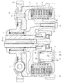
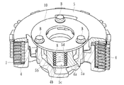
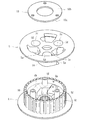
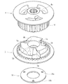
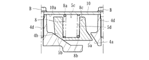
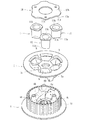
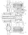
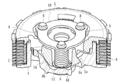
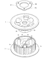
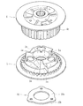
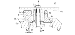
第1の実施形態に係る動力伝達装置は、二輪車等の車両に配設されて任意にエンジンの駆動力をミッションや駆動輪側へ伝達し又は遮断するためのダイカスト成形で得られるもので、図1〜11に示すように、入力部材としてのギア1が形成されたクラッチハウジング2と、出力部材としてのシャフト3と連結されたクラッチ部材4と、該クラッチ部材4の図中右端側に形成されたプレッシャ部材5と、クラッチハウジング2側に連結された駆動側クラッチ板6及びクラッチ部材4側に連結された被動側クラッチ板7と、クラッチ部材4に形成されたクラッチ部材側第1カム面4a及びクラッチ部材側第2カム面4bと、プレッシャ部材5に形成されたプレッシャ部材側第1カム面5a及びプレッシャ部材側第2カム面5bと、クラッチスプリング8と、規制部材10とから主に構成されている。尚、図中符号Sはダンパを示しているとともに、符号Nはニードルベアリングを示している。
Hereinafter, embodiments of the present invention will be specifically described with reference to the drawings.
The power transmission device according to the first embodiment is arranged in a vehicle such as a two-wheeled vehicle and is obtained by die casting for arbitrarily transmitting or shutting off the driving force of the engine to the transmission or the driving wheel side. As shown in 1 to 11, a
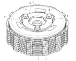
ギア1は、エンジンから伝達された駆動力(回転力)が入力されるとシャフト3を中心として回転可能とされたもので、リベットR等によりクラッチハウジング2と連結されている。このクラッチハウジング2は、同図右端側が開口した円筒状のケース部材から成り、その内周壁にはスプライン(スプライン嵌合部2a)が形成されるとともに、当該スプライン嵌合部2aには複数の駆動側クラッチ板6が取り付けられている。かかる駆動側クラッチ板6のそれぞれは、略円環状に形成された板材から成るとともにクラッチハウジング2の内周面に形成されたスプライン嵌合部2aと嵌合することにより、当該クラッチハウジング2と共に回転し、且つ、軸方向(同図中左右方向)に摺動し得るよう構成されている。
The
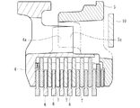
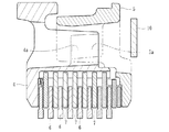
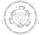
クラッチ部材4は、クラッチハウジング2内に配設された部材から成るものである。かかるクラッチ部材4の略中央には出力部材としてのシャフト3が貫通しつつスプライン嵌合により当該クラッチ部材4とシャフト3とが連結されており、クラッチ部材4が回転するとシャフト3も回転するよう構成されている。また、クラッチ部材4の外周側面には、図6、7に示すように、その軸方向(同図中上下方向)に延びるスプライン(スプライン嵌合部4c)が形成されており、該スプライン嵌合部4cに被動側クラッチ板7が嵌め込まれて取り付けられている。
The
より具体的には、クラッチ部材4に形成されたスプライン(スプライン嵌合部4c)は、図6、7に示すように、その外周側面における略全周に亘って一体的に形成された凹凸形状にて構成されており、スプラインを構成する凹溝に被動側クラッチ板7が嵌合することにより、被動側クラッチ板7のクラッチ部材4に対する軸方向の移動を許容しつつ回転方向の移動が規制され、当該クラッチ部材4と共に回転し得るよう構成されているのである。
More specifically, as shown in FIGS. 6 and 7, the spline (spline
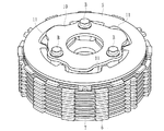
かかる被動側クラッチ板7は、駆動側クラッチ板6と交互に積層形成されており、隣接する各クラッチ板6、7が圧接又は圧接力が解放されるようになっている。即ち、両クラッチ板6、7は、クラッチ部材4の軸方向への摺動が許容されており、プレッシャ部材5にて図1中左方向へ押圧されると圧接され、クラッチハウジング2の回転力がクラッチ部材4を介してシャフト3に伝達される状態となり、プレッシャ部材5による押圧を解除すると当該圧接力が解放されてクラッチ部材4がクラッチハウジング2の回転に追従しなくなって停止し、シャフト3への回転力の伝達がなされなくなるのである。
The driven-side
プレッシャ部材5は、クラッチ部材4の軸方向(図1中左右方向)に移動が可能とされつつ当該クラッチ部材4の図中右端側の位置に取り付けられ、クラッチ部材4に対する軸方向への移動に伴い駆動側クラッチ板6と被動側クラッチ板7とを圧接させ又は圧接力を解放させ得るものである。より具体的には、プレッシャ部材5は、クラッチスプリング8により同図中左方向へ常時付勢されるとともに、シャフト3の内部には、その軸方向に延びるプッシュロッド9が配設されており、運転者が図示しないクラッチレバー等の操作手段を操作することにより当該プッシュロッド9を同図中右方向へ突出させ、プレッシャ部材5をクラッチスプリング8の付勢力に抗して右方向(クラッチ部材4から離間する方向)へ移動させることができるようになっている。
The
しかして、プレッシャ部材5が右方向へ移動すると、駆動側クラッチ板6と被動側クラッチ板7との圧接力が解かれ、ギア1及びクラッチハウジング2に入力された回転力がクラッチ部材4及びシャフト3へ伝達されず遮断されることとなる。すなわち、プレッシャ部材5は、クラッチ部材4に対する軸方向への移動に伴い駆動側クラッチ板6と被動側クラッチ板7とを圧接又は圧接力を解放させることができるよう構成されているのである。
Then, when the
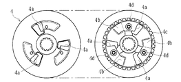
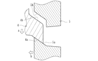
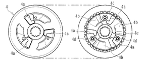
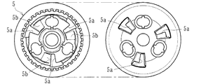
さらに、クラッチ部材4及びプレッシャ部材5には、図2、図5〜9に示すように、所定角度勾配した勾配面から成るクラッチ部材側第1カム面4a、クラッチ部材側第2カム面4b、及びプレッシャ部材側第1カム面5a、プレッシャ部材側第2カム面5bがそれぞれ形成されている。しかるに、クラッチ部材側第1カム面4aとプレッシャ部材側第1カム面5aとを対峙させて圧接アシスト用カムを構成するとともに、クラッチ部材側第2カム面4bとプレッシャ部材側第2カム面5bとを対峙させてバックトルクリミッタ用カムを構成している。
Further, as shown in FIGS. 2 and 5 to 9, the
圧接アシスト用カムは、クラッチハウジング2(入力部材)に入力された回転力がシャフト3(出力部材)に伝達され得る状態となったときにプレッシャ部材5及びクラッチ部材4が相対的に回転し、これらプレッシャ部材5及びクラッチ部材4が近接することにより駆動側クラッチ板6と被動側クラッチ板7との圧接力を増加させ得るものである。すなわち、クラッチハウジング2(入力部材)に入力された回転力がシャフト3(出力部材)に伝達され得る状態となったとき、図12に示すように、クラッチ部材4がプレッシャ部材5に対してa方向に相対的に回転するので、クラッチ部材側第1カム面4aとプレッシャ部材側第1カム面5aとが当接し、これらカム面のカムの作用により、プレッシャ部材5をb方向に移動させ、駆動側クラッチ板6と被動側クラッチ板7との圧接力を増加させるよう構成されているのである。
In the pressure welding assist cam, the
バックトルクリミッタ用カムは、シャフト3(出力部材)の回転がクラッチハウジング2(入力部材)の回転数を上回ったときにプレッシャ部材5及びクラッチ部材4が相対的に回転し、これらプレッシャ部材5及びクラッチ部材4が離間することにより駆動側クラッチ板6と被動側クラッチ板7との圧接力の解放を行わせるものである。すなわち、シャフト3(出力部材)の回転がクラッチハウジング2(入力部材)の回転数を上回ったとき、図13に示すように、クラッチ部材4がプレッシャ部材5に対してc方向に相対的に回転するので、クラッチ部材側第2カム面4bとプレッシャ部材側第2カム面5bとが当接し、これらカム面のカムの作用により、プレッシャ部材5をd方向に移動させ、駆動側クラッチ板6と被動側クラッチ板7との圧接力を解放させるよう構成されているのである。
In the back torque limiter cam, when the rotation of the shaft 3 (output member) exceeds the rotation speed of the clutch housing 2 (input member), the
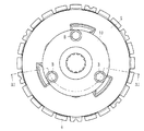
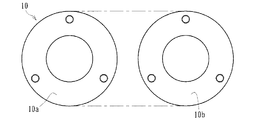
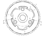
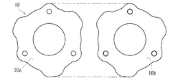
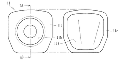
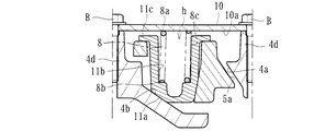
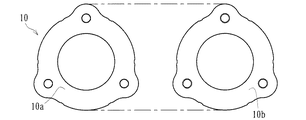
規制部材10は、所定寸法を超えてプレッシャ部材5がクラッチ部材4に対して離間する方向に移動するのを規制する円環状部材(図10参照)から成るもので、図1及び図3〜5に示すように、クラッチ部材4に形成されたボス部4dの突端に取り付けられるとともに、ボルトBにより固定されている。かかる規制部材10は、ボルトBにてクラッチ部材4に固定された状態において、その表面10aがプレッシャ部材5に向かって対峙するとともに、裏面10bが装置外部に臨むようになっている。
The regulating
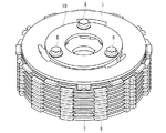
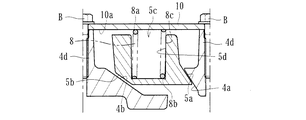
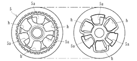
一方、本実施形態に係るプレッシャ部材5には、図6、9に示すように、複数(本実施形態においては3つ)の凹部5cが周方向に等間隔で形成されており、図1、5に示すように、これら凹部5cに対してクラッチスプリング8がそれぞれ収容されて組み付けられている。かかるクラッチスプリング8は、その一端8aが規制部材10の表面10aに当接するとともに、他端8bが凹部5cの底面又は底面近傍に当接して組み付けられており、プレッシャ部材5に対して駆動側クラッチ板6と被動側クラッチ板7とを圧接させる方向(軸方向)に付勢力を付与し得るようになっている。
On the other hand, as shown in FIGS. 6 and 9, a plurality of (three in this embodiment) recesses 5c are formed in the
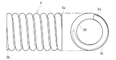
具体的には、クラッチスプリング8は、図11に示すように、一端8aから他端8bまで螺旋状に延びるコイルスプリングから成り、その長手方向(一端8aから他端8bに向かう方向)に亘って外周側面8c及び内周側面8dを有して構成されている。しかして、凹部5cにクラッチスプリング8を収容した後、ボス部4dの突端に規制部材10を固定させると、当該規制部材10にてクラッチスプリング8が圧縮され、プレッシャ部材5に対して駆動側クラッチ板6と被動側クラッチ板7とを圧接させる方向(軸方向)に付勢力を付与するのである。
Specifically, as shown in FIG. 11, the
ここで、本実施形態に係るクラッチスプリング8は、圧接アシスト用カムまたはバックトルクリミッタ用カムにおけるカム面のクリアランス(本実施形態においては、クラッチ部材側第1カム面4aとプレッシャ部材側第1カム面5aとの間に生じたクリアランス、或いはクラッチ部材側第2カム面4bとプレッシャ部材側第2カム面5bとの間に生じたクリアランス)によりプレッシャ部材5がクラッチ部材4に対して相対的に回転する際、側面(外周側面8c)が長手方向に亘って保持されつつ一端8aが規制部材10の表面10a上を摺動して回転抵抗を生じさせ得るようになっている。
Here, the
また、本実施形態に係るクラッチスプリング8は、プレッシャ部材5に形成された凹部5cに収容されて組み付けられるとともに、圧接アシスト用カムまたはバックトルクリミッタ用カムによりプレッシャ部材5がクラッチ部材4に対して相対的に回転する際、長手方向に亘る外周側面8cが当該凹部5cの内周壁面5dに当接して保持されるよう構成されている。
Further, the
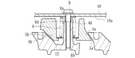
例えば、図14に示すように、圧接アシスト用カムを構成するクラッチ部材側第1カム面4aとプレッシャ部材側第1カム面5aとが当接した状態であって、バックリミッタ用カムを構成するクラッチ部材側第2カム面4bとプレッシャ部材側第2カム面5bとが寸法tのクリアランスを有して対峙している状態(セット状態)において、バックトルクリミッタ用カムが作動する際、図15に示すように、プレッシャ部材5がクラッチ部材4に対して相対的に回転するのに伴って、圧接アシスト用カムを構成するクラッチ部材側第1カム面4aとプレッシャ部材側第1カム面5aとが離間するとともに、バックリミッタ用カムを構成するクラッチ部材側第2カム面4bとプレッシャ部材側第2カム面5bとが近接する。
For example, as shown in FIG. 14, the
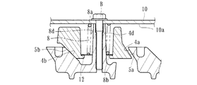
そして、図16に示すように、バックトルクリミッタ用カムを構成するクラッチ部材側第2カム面4bとプレッシャ部材側第2カム面5bとが当接し、更にプレッシャ部材5のクラッチ部材4に対する相対的な回転が行われると、カムの作用によりプレッシャ部材5及びクラッチ部材4が離間し、駆動側クラッチ板6と被動側クラッチ板7との圧接力を解放することとなる。
Then, as shown in FIG. 16, the
一方、バックトルクリミッタ用カムの作動が完了してセット状態に戻る際は、プレッシャ部材5がクラッチ部材4に対して相対的に回転するのに伴って、圧接アシスト用カムを構成するクラッチ部材側第1カム面4aとプレッシャ部材側第1カム面5aとが近接(図15参照)した後、当接(図14参照)するとともに、バックリミッタ用カムを構成するクラッチ部材側第2カム面4bとプレッシャ部材側第2カム面5bとが離間(図14、15参照)することとなる。
On the other hand, when the operation of the back torque limiter cam is completed and the cam returns to the set state, the
ここで、本実施形態に係るクラッチスプリング8は、セット状態からバックトルクリミッタ用カムが作動する際(バックトルクリミッタ用カムの作動が完了してセット状態に戻る際も同様)、図15に示すように、長手方向に亘る外周側面8cが凹部5cの内周壁面5dに当接して保持され、回転力によって傾倒又は屈曲してしまうのを抑制した状態とするとともに、一端8aが規制部材10の表面10aを摺動して回転抵抗を生じさせるので、カム面が当接する際の衝撃を緩和して打音を抑制することができることができる。
Here, the
特に、本実施形態においては、バックリミッタ用カムを構成するクラッチ部材側第2カム面4bとプレッシャ部材側第2カム面5bとの間のクリアランスの寸法tは、凹部5cの開口径寸法からクラッチスプリング8の外径寸法(外周側面8cの直径)を減算した値より大きくなるよう設定されており、クラッチスプリング8の傾倒又は屈曲を抑制しつつ回転抵抗をより確実に付与できるようになっている。
In particular, in the present embodiment, the clearance dimension t between the clutch member side
しかして、本実施形態に係るクラッチスプリング8は、通常時において、軸方向の付勢力を付与して駆動側クラッチ板6と被動側クラッチ板7とを圧接する機能を有するとともに、バックトルクリミッタ用カム(又は圧接アシスト用カム)におけるカム面のクリアランスによりプレッシャ部材5がクラッチ部材4に対して相対的に回転する際、一端8aが規制部材10の表面上を摺動して回転抵抗を生じさせる機能を有しているのである。
Therefore, the
次に、本発明の第2の実施形態について説明する。
第2の実施形態に係る動力伝達装置は、先の実施形態と同様、二輪車等の車両に配設されて任意にエンジンの駆動力をミッションや駆動輪側へ伝達し又は遮断するためのダイカスト成形で得られるもので、図17〜28に示すように、入力部材としてのギア1が形成されたクラッチハウジング2と、出力部材としてのシャフト3と連結されたクラッチ部材4と、プレッシャ部材5と、駆動側クラッチ板6及び被動側クラッチ板7と、クラッチスプリング8と、規制部材10と、収容部材11とから主に構成されている。なお、第1の実施形態と同様の構成要素には、同一の符号を付し、それらの詳細な説明を省略する。
Next, a second embodiment of the present invention will be described.
Similar to the previous embodiment, the power transmission device according to the second embodiment is arranged in a vehicle such as a two-wheeled vehicle and is die-cast molded for arbitrarily transmitting or shutting off the driving force of the engine to the transmission or the driving wheel side. As shown in FIGS. 17 to 28, a
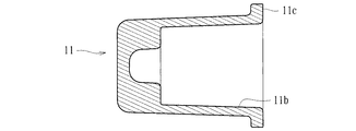
本実施形態に係るプレッシャ部材5には、図22、23、25に示すように、複数(本実施形態においては3つ)の挿通孔hが周方向に等間隔で形成されており、図17、21に示すように、これら挿通孔hに収容部材11がそれぞれ取り付けられるとともに、各収容部材11にクラッチスプリング8がそれぞれ収容されて組み付けられている。この収容部材11は、図22、23、27、28に示すように、収容部材側カム面11aと、内周壁面11bと、フランジ部11cとを有した有底筒状部材から成り、クラッチスプリング8を収容しつつフランジ部11cを挿通孔hの開口縁部に当接させて組み付けられている。
As shown in FIGS. 22, 23, and 25, a plurality of (three in this embodiment) insertion holes h are formed in the
さらに、クラッチ部材4及びプレッシャ部材5には、図18、図21〜25に示すように、所定角度勾配した勾配面から成るクラッチ部材側第1カム面4a、クラッチ部材側第2カム面4b、及びプレッシャ部材側第1カム面5aがそれぞれ形成されている。しかるに、クラッチ部材側第1カム面4aとプレッシャ部材側第1カム面5aとを対峙させて圧接アシスト用カムを構成するとともに、クラッチ部材側第2カム面4bと収容部材11に形成された収容部材側カム面11aとを対峙させてバックトルクリミッタ用カムを構成している。
Further, as shown in FIGS. 18 and 21 to 25, the
規制部材10は、所定寸法を超えてプレッシャ部材5がクラッチ部材4に対して離間する方向に移動するのを規制する円環状部材(図26参照)から成るもので、図17及び図19〜21に示すように、クラッチ部材4に形成されたボス部4dの突端に取り付けられるとともに、ボルトBにより固定されている。かかる規制部材10は、ボルトBにてクラッチ部材4に固定された状態において、その表面10aがプレッシャ部材5に向かって対峙するとともに、裏面10bが装置外部に臨むようになっている。
The regulating
一方、本実施形態に係るクラッチスプリング8は、先の実施形態と同様、その一端8aが規制部材10の表面10aに当接するとともに、他端8bが収容部材11の底面又は底面近傍に当接して組み付けられており、プレッシャ部材5に対して駆動側クラッチ板6と被動側クラッチ板7とを圧接させる方向(軸方向)に付勢力を付与し得るようになっている。なお、クラッチスプリング8については、先の実施形態と同様、一端8aから他端8bまで螺旋状に延びるコイルスプリングから成り、その長手方向(一端8aから他端8bに向かう方向)に亘って外周側面8c及び内周側面8dを有して構成されている(図11参照)。
On the other hand, in the
ここで、本実施形態に係るクラッチスプリング8は、圧接アシスト用カムまたはバックトルクリミッタ用カムにおけるカム面のクリアランス(本実施形態においては、クラッチ部材側第1カム面4aとプレッシャ部材側第1カム面5aとの間に生じたクリアランス、或いはクラッチ部材側第2カム面4bと収容部材側カム面11aとの間に生じたクリアランス)によりプレッシャ部材5がクラッチ部材4に対して相対的に回転する際、側面(外周側面8c)が長手方向に亘って保持されつつ一端8aが規制部材10の表面10a上を摺動して回転抵抗を生じさせ得るようになっている。
Here, the
また、本実施形態に係るクラッチスプリング8は、プレッシャ部材5に取り付けられた収容部材11に収容されて組み付けられるとともに、圧接アシスト用カムまたはバックトルクリミッタ用カムによりプレッシャ部材5がクラッチ部材4に対して相対的に回転する際、長手方向に亘る外周側面8cが当該収容部材11の内周壁面11bに当接して保持されるよう構成されている。
Further, the
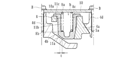
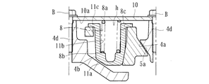
例えば、図29に示すように、圧接アシスト用カムを構成するクラッチ部材側第1カム面4aとプレッシャ部材側第1カム面5aとが当接した状態であって、バックリミッタ用カムを構成するクラッチ部材側第2カム面4bと収容部材11の収容部材側カム面11aとが寸法tのクリアランスを有して対峙している状態(セット状態)において、バックトルクリミッタ用カムが作動する際、図30に示すように、プレッシャ部材5がクラッチ部材4に対して相対的に回転するのに伴って、圧接アシスト用カムを構成するクラッチ部材側第1カム面4aとプレッシャ部材側第1カム面5aとが離間するとともに、バックリミッタ用カムを構成するクラッチ部材側第2カム面4bと収容部材側カム面11aとが近接する。
For example, as shown in FIG. 29, the
そして、図31に示すように、バックトルクリミッタ用カムを構成するクラッチ部材側第2カム面4bと収容部材側カム面11aとが当接し、更にプレッシャ部材5のクラッチ部材4に対する相対的な回転が行われると、カムの作用によりプレッシャ部材5及びクラッチ部材4が離間し、駆動側クラッチ板6と被動側クラッチ板7との圧接力を解放することとなる。
Then, as shown in FIG. 31, the
一方、バックトルクリミッタ用カムの作動が完了してセット状態に戻る際は、プレッシャ部材5がクラッチ部材4に対して相対的に回転するのに伴って、圧接アシスト用カムを構成するクラッチ部材側第1カム面4aとプレッシャ部材側第1カム面5aとが近接(図30参照)した後、当接(図29参照)するとともに、バックリミッタ用カムを構成するクラッチ部材側第2カム面4bと収容部材側カム面11aとが離間(図29、30参照)することとなる。
On the other hand, when the operation of the back torque limiter cam is completed and the cam returns to the set state, the
ここで、本実施形態に係るクラッチスプリング8は、セット状態からバックトルクリミッタ用カムが作動する際(バックトルクリミッタ用カムの作動が完了してセット状態に戻る際も同様)、図30に示すように、長手方向に亘る外周側面8cが収容部材11の内周壁面11bに当接して保持され、回転力によって傾倒又は屈曲してしまうのを抑制した状態とするとともに、一端8aが規制部材10の表面10aを摺動して回転抵抗を生じさせるので、カム面が当接する際の衝撃を緩和して打音を抑制することができることができる。
Here, the
特に、本実施形態においては、バックリミッタ用カムを構成するクラッチ部材側第2カム面4bと収容部材側カム面11aとの間のクリアランスの寸法tは、収容部材11の開口径寸法からクラッチスプリング8の外径寸法(外周側面8cの直径)を減算した値より大きくなるよう設定されており、クラッチスプリング8の傾倒又は屈曲を抑制しつつ回転抵抗をより確実に付与できるようになっている。
In particular, in the present embodiment, the dimension t of the clearance between the
しかして、本実施形態に係るクラッチスプリング8は、通常時において、軸方向の付勢力を付与して駆動側クラッチ板6と被動側クラッチ板7とを圧接する機能を有するとともに、バックトルクリミッタ用カム(又は圧接アシスト用カム)におけるカム面のクリアランスによりプレッシャ部材5がクラッチ部材4に対して相対的に回転する際、一端8aが規制部材10の表面上を摺動して回転抵抗を生じさせる機能を有しているのである。
Therefore, the
次に、本発明の第3の実施形態について説明する。
第3の実施形態に係る動力伝達装置は、先の実施形態と同様、二輪車等の車両に配設されて任意にエンジンの駆動力をミッションや駆動輪側へ伝達し又は遮断するためのダイカスト成形で得られるもので、図32〜40に示すように、入力部材としてのギア1が形成されたクラッチハウジング2と、出力部材としてのシャフト3と連結されたクラッチ部材4と、プレッシャ部材5と、駆動側クラッチ板6及び被動側クラッチ板7と、クラッチスプリング8と、規制部材10と、クラッチスプリング8の座面を構成するスプリングシート12とから主に構成されている。なお、第1、2の実施形態と同様の構成要素には、同一の符号を付し、それらの詳細な説明を省略する。
Next, a third embodiment of the present invention will be described.
Similar to the previous embodiment, the power transmission device according to the third embodiment is arranged in a vehicle such as a two-wheeled vehicle and is die-cast molded for arbitrarily transmitting or shutting off the driving force of the engine to the transmission or the driving wheel side. As shown in FIGS. 32 to 40, a
本実施形態に係るクラッチ部材4には、図36、38に示すように、複数(本実施形態においては3つ)のボス部4dが周方向に等間隔で形成されており、図32、35に示すように、これらボス部4dにクラッチスプリング8がそれぞれ挿通して組み付けられている。そして、ボス部4dにクラッチスプリング8を組み付けると、その一端8aが規制部材10の表面10aに当接するとともに、他端8bがプレッシャ部材5に取り付けられたスプリングシート12に当接するようになっている。かかるスプリングシート12は、クラッチスプリング8の座面を構成するもので、当該クラッチスプリング8の付勢力を受けて、プレッシャ部材5を押圧し得るよう構成されている。
As shown in FIGS. 36 and 38, a plurality of (three in this embodiment)
さらに、クラッチ部材4及びプレッシャ部材5には、図32〜39に示すように、所定角度勾配した勾配面から成るクラッチ部材側第1カム面4a、クラッチ部材側第2カム面4b、及びプレッシャ部材側第1カム面5a、プレッシャ部材側第2カム面5bがそれぞれ形成されている。しかるに、クラッチ部材側第1カム面4aとプレッシャ部材側第1カム面5aとを対峙させて圧接アシスト用カムを構成するとともに、クラッチ部材側第2カム面4bとプレッシャ部材側第2カム面5bとを対峙させてバックトルクリミッタ用カムを構成している。
Further, as shown in FIGS. 32 to 39, the
規制部材10は、所定寸法を超えてプレッシャ部材5がクラッチ部材4に対して離間する方向に移動するのを規制する円環状部材(図40参照)から成るもので、図32及び図33〜35に示すように、クラッチ部材4に形成されたボス部4dの突端に取り付けられるとともに、ボルトBにより固定されている。かかる規制部材10は、ボルトBにてクラッチ部材4に固定された状態において、その表面10aがプレッシャ部材5に向かって対峙するとともに、裏面10bが装置外部に臨むようになっている。
The regulating
一方、本実施形態に係るクラッチスプリング8は、先の実施形態と同様、その一端8aが規制部材10の表面10aに当接するとともに、他端8bがスプリングシート12に当接して組み付けられており、プレッシャ部材5に対して駆動側クラッチ板6と被動側クラッチ板7とを圧接させる方向(軸方向)に付勢力を付与し得るようになっている。なお、クラッチスプリング8については、先の実施形態と同様、一端8aから他端8bまで螺旋状に延びるコイルスプリングから成り、その長手方向(一端8aから他端8bに向かう方向)に亘って外周側面8c及び内周側面8dを有して構成されている(図11参照)。
On the other hand, the
ここで、本実施形態に係るクラッチスプリング8は、圧接アシスト用カムまたはバックトルクリミッタ用カムにおけるカム面のクリアランス(本実施形態においては、クラッチ部材側第1カム面4aとプレッシャ部材側第1カム面5aとの間に生じたクリアランス、或いはクラッチ部材側第2カム面4bとプレッシャ部材側第2カム面5bとの間に生じたクリアランス)によりプレッシャ部材5がクラッチ部材4に対して相対的に回転する際、側面(内周側面8d)が長手方向に亘って保持されつつ他端8bがスプリングシート12の表面上を摺動して回転抵抗を生じさせ得るようになっている。
Here, the
また、本実施形態に係るクラッチスプリング8は、クラッチ部材4に形成されたボス部4dに挿通されて組み付けられるとともに、圧接アシスト用カムまたはバックトルクリミッタ用カムによりプレッシャ部材5がクラッチ部材4に対して相対的に回転する際、長手方向に亘る内周側面8dが当該ボス部4dの外周面に当接して保持されるよう構成されている。
Further, the
例えば、図41に示すように、圧接アシスト用カムを構成するクラッチ部材側第1カム面4aとプレッシャ部材側第1カム面5aとが当接した状態であって、バックリミッタ用カムを構成するクラッチ部材側第2カム面4bとプレッシャ部材側第2カム面5bとが寸法tのクリアランスを有して対峙している状態(セット状態)において、バックトルクリミッタ用カムが作動する際、図42に示すように、プレッシャ部材5がクラッチ部材4に対して相対的に回転するのに伴って、圧接アシスト用カムを構成するクラッチ部材側第1カム面4aとプレッシャ部材側第1カム面5aとが離間するとともに、バックリミッタ用カムを構成するクラッチ部材側第2カム面4bとプレッシャ部材側第2カム面5bとが近接する。
For example, as shown in FIG. 41, the
そして、図43に示すように、バックトルクリミッタ用カムを構成するクラッチ部材側第2カム面4bとプレッシャ部材側第2カム面5bとが当接し、更にプレッシャ部材5のクラッチ部材4に対する相対的な回転が行われると、カムの作用によりプレッシャ部材5及びクラッチ部材4が離間し、駆動側クラッチ板6と被動側クラッチ板7との圧接力を解放することとなる。
Then, as shown in FIG. 43, the
一方、バックトルクリミッタ用カムの作動が完了してセット状態に戻る際は、プレッシャ部材5がクラッチ部材4に対して相対的に回転するのに伴って、圧接アシスト用カムを構成するクラッチ部材側第1カム面4aとプレッシャ部材側第1カム面5aとが近接(図42参照)した後、当接(図41参照)するとともに、バックリミッタ用カムを構成するクラッチ部材側第2カム面4bとプレッシャ部材側第2カム面5bとが離間(図41、42参照)することとなる。
On the other hand, when the operation of the back torque limiter cam is completed and the cam returns to the set state, the
ここで、本実施形態に係るクラッチスプリング8は、セット状態からバックトルクリミッタ用カムが作動する際(バックトルクリミッタ用カムの作動が完了してセット状態に戻る際も同様)、図42に示すように、長手方向に亘る内周側面8dがボス部4dの外周面に当接して保持され、回転力によって傾倒又は屈曲してしまうのを抑制した状態とするとともに、他端8bがスプリングシート12の表面を摺動して回転抵抗を生じさせるので、カム面が当接する際の衝撃を緩和して打音を抑制することができることができる。
Here, the
特に、本実施形態においては、バックリミッタ用カムを構成するクラッチ部材側第2カム面4bとプレッシャ部材側第2カム面5bとの間のクリアランスの寸法tは、クラッチスプリング8の内径寸法(内周側面8dの直径)からボス部4dの外径寸法(直径)を減算した値より大きくなるよう設定されており、クラッチスプリング8の傾倒又は屈曲を抑制しつつ回転抵抗をより確実に付与できるようになっている。
In particular, in the present embodiment, the clearance dimension t between the clutch member side
しかして、本実施形態に係るクラッチスプリング8は、通常時において、軸方向の付勢力を付与して駆動側クラッチ板6と被動側クラッチ板7とを圧接する機能を有するとともに、バックトルクリミッタ用カム(又は圧接アシスト用カム)におけるカム面のクリアランスによりプレッシャ部材5がクラッチ部材4に対して相対的に回転する際、他端8bがスプリングシート12の表面上を摺動して回転抵抗を生じさせる機能を有しているのである。
Therefore, the
上記第1、2の実施形態によれば、クラッチスプリング8は、圧接アシスト用カムまたはバックトルクリミッタ用カムにおけるカム面のクリアランスによりプレッシャ部材5がクラッチ部材5に対して相対的に回転する際、側面(第1、2の実施形態においては外周側面8c)が長手方向に亘って保持されつつ一端8aが規制部材10の表面10a上を摺動して回転抵抗を生じさせ得るので、クラッチスプリング8によってプレッシャ部材4のクラッチ部材5に対する相対的な回転に対して回転抵抗を付与することができ、専用の別部材を用いることなく(規制部材10を流用して)、圧接アシスト用カム又はバックトルクリミッタ用カムにおけるカム面が当接する際の衝撃や打音を抑制することができる。
According to the first and second embodiments, when the
また、上記第3の実施形態によれば、クラッチスプリング8は、圧接アシスト用カムまたはバックトルクリミッタ用カムにおけるカム面のクリアランスによりプレッシャ部材5がクラッチ部材5に対して相対的に回転する際、側面(第3の実施形態においては内周側面8d)が長手方向に亘って保持されつつ他端8bがスプリングシート12の表面上を摺動して回転抵抗を生じさせ得るので、クラッチスプリング8によってプレッシャ部材4のクラッチ部材5に対する相対的な回転に対して回転抵抗を付与することができ、専用の別部材を用いることなく(スプリングシート12を流用して)、圧接アシスト用カム又はバックトルクリミッタ用カムにおけるカム面が当接する際の衝撃や打音を抑制することができる。
Further, according to the third embodiment, when the
特に、上記第1の実施形態によれば、クラッチスプリング8は、プレッシャ部材5に形成された凹部5cに収容されて組み付けられるとともに、圧接アシスト用カムまたはバックトルクリミッタ用カムによりプレッシャ部材5がクラッチ部材4に対して相対的に回転する際、長手方向に亘る外周側面8cが当該凹部5cの内周壁面5dに当接して保持されるので、回転抵抗を生じさせる際にクラッチスプリング8が傾倒又は屈曲してしまうのを凹部5cの内周壁面5dによって防止することができ、必要な回転抵抗をより確実に生じさせることができる。
In particular, according to the first embodiment, the
また、上記第2の実施形態によれば、クラッチスプリング8は、プレッシャ部材5に取り付けられた収容部材11に収容されて組み付けられるとともに、圧接アシスト用カムまたはバックトルクリミッタ用カムによりプレッシャ部材5がクラッチ部材4に対して相対的に回転する際、長手方向に亘る外周側面8cが当該収容部材11の内周壁面11bに当接して保持されるので、回転抵抗を生じさせる際にクラッチスプリング8が傾倒又は屈曲してしまうのを収容部材11の内周壁面11bによって防止することができ、必要な回転抵抗をより確実に生じさせることができる。
Further, according to the second embodiment, the
さらに、上記第3の実施形態によれば、クラッチスプリング8は、クラッチ部材4に形成されたボス部4dに挿通されて組み付けられるとともに、圧接アシスト用カムまたはバックトルクリミッタ用カムによりプレッシャ部材5がクラッチ部材4に対して相対的に回転する際、長手方向に亘る内周側面8dが当該ボス部4dの外周面に当接して保持されるので、回転抵抗を生じさせる際にクラッチスプリング8が傾倒又は屈曲してしまうのをボス部4dの外周面によって防止することができ、必要な回転抵抗をより確実に生じさせることができる。
Further, according to the third embodiment, the
以上、本実施形態について説明したが、本発明はこれらに限定されるものではなく、例えば規制部材10の表面10a又はスプリングシート12の表面について、少なくともクラッチスプリング8の一端8a又は他端8bが摺動する摺動面が硬化処理されて成るのが好ましく、当該硬化処理として、浸炭処理等が好ましい。このように、規制部材10又はスプリングシート12について、少なくともクラッチスプリング8の一端8a又は他端8bが摺動する摺動面が硬化処理されて成るようにすれば、繰り返しの摺動によって規制部材10又はスプリングシート12の摺動面が摩耗してしまうのを抑制することができ、摩耗による動作不良を防止することができる。
Although the present embodiment has been described above, the present invention is not limited thereto. For example, at least one
また、本実施形態においては、何れも圧接アシスト用カム及びバックトルクリミッタ用カムの両方が形成されているが、例えば圧接アシスト用カムが形成されず、バックトルクリミッタ用カムのみ形成されたものに適用してもよい。なお、本発明の動力伝達装置は、自動二輪車の他、自動車、3輪又は4輪バギー、或いは汎用機等種々の多板クラッチ型の動力伝達装置に適用することができる。 Further, in the present embodiment, both the pressure welding assist cam and the back torque limiter cam are formed, but for example, the pressure welding assist cam is not formed and only the back torque limiter cam is formed. It may be applied. The power transmission device of the present invention can be applied to various multi-plate clutch type power transmission devices such as automobiles, three-wheel or four-wheel buggies, and general-purpose machines, in addition to motorcycles.
圧接アシスト用カムまたはバックトルクリミッタ用カムにおけるカム面のクリアランスによりプレッシャ部材がクラッチ部材に対して相対的に回転する際、クラッチスプリングの側面が長手方向に亘って保持されつつ一端又は他端が規制部材又は前記クラッチスプリングの座面を構成するスプリングシートの表面上を摺動して回転抵抗を生じさせ得る動力伝達装置であれば、外観形状が異なるもの或いは他の機能が付加されたもの等にも適用することができる。 When the pressure member rotates relative to the clutch member due to the clearance of the cam surface in the pressure welding assist cam or the back torque limiter cam, one end or the other end is restricted while the side surface of the clutch spring is held in the longitudinal direction. If it is a power transmission device that can slide on the surface of a member or a spring seat that constitutes the seating surface of the clutch spring to generate rotational resistance, the appearance shape may be different, or other functions may be added. Can also be applied.
1 ギア(入力部材)
2 クラッチハウジング(入力部材)
2a スプライン嵌合部
3 シャフト(出力部材)
4 クラッチ部材
4a クラッチ部材側第1カム面
4b クラッチ部材側第2カム面
4c スプライン嵌合部
4d ボス部
5 プレッシャ部材
5a プレッシャ部材側第1カム面
5b プレッシャ部材側第2カム面
5c 凹部
5d 内周壁面
6 駆動側クラッチ板
7 被動側クラッチ板
8 クラッチスプリング
8a 一端
8b 他端
8c 外周側面
8d 内周側面
9 プッシュロッド
10 規制部材
10a 表面
10b 裏面
11 収容部材
11a 収容部材側カム面
11b 内周壁面
11c フランジ部
12 スプリングシート
h 挿通孔
1 gear (input member)
2 Clutch housing (input member)
2a Spline
4
Claims (3)
前記クラッチハウジングの駆動側クラッチ板と交互に形成された複数の被動側クラッチ板が取り付けられるとともに、出力部材と連結されたクラッチ部材と、
前記クラッチ部材の軸方向に移動が可能とされつつ当該クラッチ部材に取り付けられ、クラッチ部材に対する軸方向への移動に伴い前記駆動側クラッチ板と被動側クラッチ板とを圧接させ又は圧接力を解放させ得るプレッシャ部材と、
前記クラッチ部材に取り付けられ、前記プレッシャ部材が当該クラッチ部材から所定寸法離間するのを規制し得る規制部材と、
一端が前記規制部材の表面に当接して組み付けられ、前記プレッシャ部材に対して前記駆動側クラッチ板と被動側クラッチ板とを圧接させる方向に付勢力を付与するクラッチスプリングと、
前記入力部材に入力された回転力が前記出力部材に伝達され得る状態となったときに前記プレッシャ部材及び前記クラッチ部材が相対的に回転して近接することにより前記駆動側クラッチ板と被動側クラッチ板との圧接力を増加させ得る圧接アシスト用カム、または前記出力部材の回転が前記入力部材の回転数を上回ったときに前記プレッシャ部材及び前記クラッチ部材が相対的に回転して離間することにより前記駆動側クラッチ板と被動側クラッチ板との圧接力の解放を行わせるバックトルクリミッタ用カムと、
を有し、前記駆動側クラッチ板と被動側クラッチ板との圧接又は圧接力の解放により、入力部材に入力された回転力を出力部材に伝達し又は遮断し得る動力伝達装置において、
前記クラッチスプリングは、前記プレッシャ部材に形成された凹部に収容されて組み付けられるとともに、前記圧接アシスト用カムまたはバックトルクリミッタ用カムにおけるカム面のクリアランスにより前記プレッシャ部材が前記クラッチ部材に対して相対的に回転する際、長手方向に亘る外周側面が当該凹部の内周壁面に当接して保持されつつ前記一端が前記規制部材の表面上を摺動して回転抵抗を生じさせ得ることを特徴とする動力伝達装置。 A clutch housing that rotates with the input member and has multiple drive-side clutch plates attached to it.
A plurality of driven side clutch plates formed alternately with the drive side clutch plate of the clutch housing are attached, and the clutch member connected to the output member and the clutch member
The clutch member is attached to the clutch member while being able to move in the axial direction, and the drive-side clutch plate and the driven-side clutch plate are brought into pressure contact with each other or the pressure contact force is released as the clutch member moves in the axial direction. The pressure member to get and
A regulating member that is attached to the clutch member and can regulate the pressure member from being separated from the clutch member by a predetermined dimension.
A clutch spring, one end of which is assembled in contact with the surface of the regulating member to apply an urging force to the pressure member in a direction in which the driving side clutch plate and the driven side clutch plate are brought into pressure contact with each other.
When the rotational force input to the input member is in a state where it can be transmitted to the output member, the pressure member and the clutch member rotate relatively and come close to each other, so that the drive side clutch plate and the driven side clutch When the rotation of the pressure welding assist cam that can increase the pressure contact force with the plate or the output member exceeds the rotation speed of the input member, the pressure member and the clutch member are relatively rotated and separated from each other. A back torque limiter cam that releases the pressure contact force between the drive-side clutch plate and the driven-side clutch plate, and
In a power transmission device capable of transmitting or blocking the rotational force input to the input member to the output member by pressing or releasing the pressure contact force between the driving side clutch plate and the driven side clutch plate.
The clutch spring is housed and assembled in a recess formed in the pressure member, and the pressure member is relative to the clutch member due to the clearance of the cam surface in the pressure welding assist cam or the back torque limiter cam. characterized in that during rotation, the outer peripheral side surface over the longitudinal direction inner peripheral contact the one end while being held on the wall surface of the recessed portion can cause rotational resistance to sliding on the surface of the regulating member in Power transmission device.
前記クラッチハウジングの駆動側クラッチ板と交互に形成された複数の被動側クラッチ板が取り付けられるとともに、出力部材と連結されたクラッチ部材と、
前記クラッチ部材の軸方向に移動が可能とされつつ当該クラッチ部材に取り付けられ、クラッチ部材に対する軸方向への移動に伴い前記駆動側クラッチ板と被動側クラッチ板とを圧接させ又は圧接力を解放させ得るプレッシャ部材と、
前記クラッチ部材に取り付けられ、前記プレッシャ部材が当該クラッチ部材から所定寸法離間するのを規制し得る規制部材と、
一端が前記規制部材の表面に当接して組み付けられ、前記プレッシャ部材に対して前記駆動側クラッチ板と被動側クラッチ板とを圧接させる方向に付勢力を付与するクラッチスプリングと、
前記入力部材に入力された回転力が前記出力部材に伝達され得る状態となったときに前記プレッシャ部材及び前記クラッチ部材が相対的に回転して近接することにより前記駆動側クラッチ板と被動側クラッチ板との圧接力を増加させ得る圧接アシスト用カム、または前記出力部材の回転が前記入力部材の回転数を上回ったときに前記プレッシャ部材及び前記クラッチ部材が相対的に回転して離間することにより前記駆動側クラッチ板と被動側クラッチ板との圧接力の解放を行わせるバックトルクリミッタ用カムと、
を有し、前記駆動側クラッチ板と被動側クラッチ板との圧接又は圧接力の解放により、入力部材に入力された回転力を出力部材に伝達し又は遮断し得る動力伝達装置において、
前記クラッチスプリングは、前記プレッシャ部材に取り付けられた収容部材に収容されて組み付けられるとともに、前記圧接アシスト用カムまたはバックトルクリミッタ用カムにおけるカム面のクリアランスにより前記プレッシャ部材が前記クラッチ部材に対して相対的に回転する際、長手方向に亘る外周側面が当該収容部材の内周壁面に当接して保持されつつ前記一端が前記規制部材の表面上を摺動して回転抵抗を生じさせ得ることを特徴とする動力伝達装置。 A clutch housing that rotates with the input member and has multiple drive-side clutch plates attached to it.
A plurality of driven side clutch plates formed alternately with the drive side clutch plate of the clutch housing are attached, and the clutch member connected to the output member and the clutch member
The clutch member is attached to the clutch member while being able to move in the axial direction, and the drive-side clutch plate and the driven-side clutch plate are brought into pressure contact with each other or the pressure contact force is released as the clutch member moves in the axial direction. The pressure member to get and
A regulating member that is attached to the clutch member and can regulate the pressure member from being separated from the clutch member by a predetermined dimension.
A clutch spring, one end of which is assembled in contact with the surface of the regulating member to apply an urging force to the pressure member in a direction in which the driving side clutch plate and the driven side clutch plate are brought into pressure contact with each other.
When the rotational force input to the input member is in a state where it can be transmitted to the output member, the pressure member and the clutch member rotate relatively and come close to each other, so that the drive side clutch plate and the driven side clutch When the rotation of the pressure welding assist cam that can increase the pressure contact force with the plate or the output member exceeds the rotation speed of the input member, the pressure member and the clutch member are relatively rotated and separated from each other. A back torque limiter cam that releases the pressure contact force between the drive-side clutch plate and the driven-side clutch plate, and
In a power transmission device capable of transmitting or blocking the rotational force input to the input member to the output member by pressing or releasing the pressure contact force between the driving side clutch plate and the driven side clutch plate.
The clutch spring is accommodated and assembled in the accommodating member attached to the pressure member, and the pressure member is relative to the clutch member due to the clearance of the cam surface in the pressure contact assist cam or the back torque limiter cam. manner during rotation, the outer peripheral side surface over the longitudinal direction said one end to the inner peripheral wall surface while being held in contact with the said housing member may cause rotational resistance to sliding on the surface of the regulating member A power transmission device characterized by.
Priority Applications (7)
| Application Number | Priority Date | Filing Date | Title |
|---|---|---|---|
| JP2017145838A JP6894792B2 (en) | 2017-07-27 | 2017-07-27 | Power transmission device |
| TW107123874A TWI769277B (en) | 2017-07-27 | 2018-07-10 | power transmission |
| PCT/JP2018/028052 WO2019022190A1 (en) | 2017-07-27 | 2018-07-26 | Power transmission device |
| EP18837647.9A EP3660348B9 (en) | 2017-07-27 | 2018-07-26 | Power transmission device |
| CN201880049886.5A CN110998120B (en) | 2017-07-27 | 2018-07-26 | power transmission equipment |
| BR112020001756-6A BR112020001756B1 (en) | 2017-07-27 | 2018-07-26 | POWER TRANSMISSION DEVICE |
| US16/751,453 US11391328B2 (en) | 2017-07-27 | 2020-01-24 | Power transmitting apparatus |
Applications Claiming Priority (1)
| Application Number | Priority Date | Filing Date | Title |
|---|---|---|---|
| JP2017145838A JP6894792B2 (en) | 2017-07-27 | 2017-07-27 | Power transmission device |
Publications (2)
| Publication Number | Publication Date |
|---|---|
| JP2019027483A JP2019027483A (en) | 2019-02-21 |
| JP6894792B2 true JP6894792B2 (en) | 2021-06-30 |
Family
ID=65040626
Family Applications (1)
| Application Number | Title | Priority Date | Filing Date |
|---|---|---|---|
| JP2017145838A Active JP6894792B2 (en) | 2017-07-27 | 2017-07-27 | Power transmission device |
Country Status (6)
| Country | Link |
|---|---|
| US (1) | US11391328B2 (en) |
| EP (1) | EP3660348B9 (en) |
| JP (1) | JP6894792B2 (en) |
| CN (1) | CN110998120B (en) |
| TW (1) | TWI769277B (en) |
| WO (1) | WO2019022190A1 (en) |
Cited By (10)
| Publication number | Priority date | Publication date | Assignee | Title |
|---|---|---|---|---|
| JP7203271B1 (en) | 2022-09-13 | 2023-01-12 | 株式会社エフ・シー・シー | Clutch device, motorcycle, and method for manufacturing pressure plate |
| US11859674B1 (en) | 2022-09-28 | 2024-01-02 | Kabushiki Kaisha F.C.C. | Clutch device and motorcycle |
| WO2024014284A1 (en) | 2022-07-15 | 2024-01-18 | 株式会社エフ・シー・シー | Clutch device and motorcycle |
| EP4339474A1 (en) | 2022-09-13 | 2024-03-20 | Kabushiki Kaisha F.C.C. | Clutch device, motorcycle, and method for producing pressure plate |
| US11940013B1 (en) | 2022-09-13 | 2024-03-26 | Kabushiki Kaisha F.C.C. | Clutch device and motorcycle |
| US11946513B1 (en) | 2022-09-13 | 2024-04-02 | Kabushiki Kaisha F.C.C. | Clutch device and motorcycle |
| WO2024070742A1 (en) | 2022-09-28 | 2024-04-04 | 株式会社エフ・シー・シー | Clutch device, and motorcycle |
| WO2024214479A1 (en) | 2023-04-14 | 2024-10-17 | 株式会社エフ・シー・シー | Clutch device |
| JP2024177495A (en) * | 2023-04-14 | 2024-12-19 | 株式会社エフ・シー・シー | Clutch device |
| WO2025126779A1 (en) * | 2023-12-15 | 2025-06-19 | 株式会社エフ・シー・シー | Clutch device |
Families Citing this family (5)
| Publication number | Priority date | Publication date | Assignee | Title |
|---|---|---|---|---|
| IT201700031815A1 (en) * | 2017-03-22 | 2018-09-22 | Adler Spa | Clutch, in particular clutch for motorcycles, and relative mounting method |
| EP4180680B1 (en) * | 2020-04-13 | 2024-08-28 | Kabushiki Kaisha F.C.C. | Power transmission device |
| JP7255009B1 (en) | 2022-07-06 | 2023-04-10 | 株式会社エフ・シー・シー | Clutch device and motorcycle |
| JP7581288B2 (en) * | 2022-07-21 | 2024-11-12 | 株式会社エフ・シー・シー | Clutch device |
| JP7196356B1 (en) * | 2022-09-06 | 2022-12-26 | 株式会社エフ・シー・シー | Clutch device and motorcycle |
Family Cites Families (15)
| Publication number | Priority date | Publication date | Assignee | Title |
|---|---|---|---|---|
| JP3328311B2 (en) * | 1991-03-20 | 2002-09-24 | 本田技研工業株式会社 | Multi-plate clutch |
| JPH0979285A (en) * | 1995-09-12 | 1997-03-25 | Exedy Corp | Damper disk assembly unit |
| JP2002145085A (en) * | 2000-11-13 | 2002-05-22 | Mitsubishi Electric Corp | Electric power steering device |
| JP4344396B2 (en) * | 2007-09-12 | 2009-10-14 | 株式会社エフ・シー・シー | Power transmission device |
| JP4452301B2 (en) * | 2007-09-12 | 2010-04-21 | 株式会社エフ・シー・シー | Power transmission device |
| JP5198188B2 (en) * | 2008-08-29 | 2013-05-15 | 本田技研工業株式会社 | Oil passage for wet multi-plate clutch |
| JP5502507B2 (en) * | 2010-01-27 | 2014-05-28 | 株式会社エフ・シー・シー | Power transmission device |
| JP5847551B2 (en) * | 2011-11-17 | 2016-01-27 | 株式会社エフ・シー・シー | Clutch device |
| JP5995439B2 (en) * | 2011-12-28 | 2016-09-21 | 株式会社エフ・シー・シー | Power transmission device |
| WO2013183588A1 (en) * | 2012-06-04 | 2013-12-12 | 株式会社エフ・シ-・シ- | Power transmission device |
| CN106715944B8 (en) * | 2014-08-12 | 2019-09-20 | 株式会社F.C.C. | power transmission |
| JP6501354B2 (en) * | 2015-05-12 | 2019-04-17 | 株式会社エフ・シー・シー | Power transmission system for vehicles |
| JP6649067B2 (en) * | 2015-12-04 | 2020-02-19 | 株式会社エクセディ | Motorcycle clutch device |
| JP7217588B2 (en) * | 2018-01-11 | 2023-02-03 | 株式会社エフ・シー・シー | power transmission device |
| JP6903020B2 (en) * | 2018-01-11 | 2021-07-14 | 株式会社エフ・シー・シー | Power transmission device |
-
2017
- 2017-07-27 JP JP2017145838A patent/JP6894792B2/en active Active
-
2018
- 2018-07-10 TW TW107123874A patent/TWI769277B/en active
- 2018-07-26 WO PCT/JP2018/028052 patent/WO2019022190A1/en not_active Ceased
- 2018-07-26 CN CN201880049886.5A patent/CN110998120B/en active Active
- 2018-07-26 EP EP18837647.9A patent/EP3660348B9/en active Active
-
2020
- 2020-01-24 US US16/751,453 patent/US11391328B2/en active Active
Cited By (24)
| Publication number | Priority date | Publication date | Assignee | Title |
|---|---|---|---|---|
| WO2024014284A1 (en) | 2022-07-15 | 2024-01-18 | 株式会社エフ・シー・シー | Clutch device and motorcycle |
| WO2024014283A1 (en) | 2022-07-15 | 2024-01-18 | 株式会社エフ・シー・シー | Clutch device and motorcycle |
| US11946513B1 (en) | 2022-09-13 | 2024-04-02 | Kabushiki Kaisha F.C.C. | Clutch device and motorcycle |
| JP7403620B1 (en) | 2022-09-13 | 2023-12-22 | 株式会社エフ・シー・シー | Clutch device, motorcycle, and pressure plate manufacturing method |
| JP7203271B1 (en) | 2022-09-13 | 2023-01-12 | 株式会社エフ・シー・シー | Clutch device, motorcycle, and method for manufacturing pressure plate |
| US11933369B1 (en) | 2022-09-13 | 2024-03-19 | Kabushiki Kaisha F.C.C. | Clutch device, motorcycle, and method for producing pressure plate |
| EP4339474A1 (en) | 2022-09-13 | 2024-03-20 | Kabushiki Kaisha F.C.C. | Clutch device, motorcycle, and method for producing pressure plate |
| WO2024058174A1 (en) | 2022-09-13 | 2024-03-21 | 株式会社エフ・シー・シー | Clutch device, motorcycle, and manufacturing method for pressure plate |
| JP2024041020A (en) * | 2022-09-13 | 2024-03-26 | 株式会社エフ・シー・シー | Clutch device, motorcycle, and pressure plate manufacturing method |
| JP2024040959A (en) * | 2022-09-13 | 2024-03-26 | 株式会社エフ・シー・シー | Clutch device, motorcycle, and pressure plate manufacturing method |
| US11940013B1 (en) | 2022-09-13 | 2024-03-26 | Kabushiki Kaisha F.C.C. | Clutch device and motorcycle |
| WO2024070742A1 (en) | 2022-09-28 | 2024-04-04 | 株式会社エフ・シー・シー | Clutch device, and motorcycle |
| US11859674B1 (en) | 2022-09-28 | 2024-01-02 | Kabushiki Kaisha F.C.C. | Clutch device and motorcycle |
| WO2024214479A1 (en) | 2023-04-14 | 2024-10-17 | 株式会社エフ・シー・シー | Clutch device |
| JPWO2024214479A1 (en) * | 2023-04-14 | 2024-10-17 | ||
| JP2024177495A (en) * | 2023-04-14 | 2024-12-19 | 株式会社エフ・シー・シー | Clutch device |
| JP2025036742A (en) * | 2023-04-14 | 2025-03-14 | 株式会社エフ・シー・シー | Clutch device |
| JP2025036743A (en) * | 2023-04-14 | 2025-03-14 | 株式会社エフ・シー・シー | Clutch device |
| JP7651051B2 (en) | 2023-04-14 | 2025-03-25 | 株式会社エフ・シー・シー | Clutch device |
| JP7696519B2 (en) | 2023-04-14 | 2025-06-20 | 株式会社エフ・シー・シー | Clutch device |
| JP7715961B1 (en) | 2023-04-14 | 2025-07-30 | 株式会社エフ・シー・シー | Clutch device |
| JP2025116209A (en) * | 2023-04-14 | 2025-08-07 | 株式会社エフ・シー・シー | Clutch device |
| JP7727134B2 (en) | 2023-04-14 | 2025-08-20 | 株式会社エフ・シー・シー | Clutch device |
| WO2025126779A1 (en) * | 2023-12-15 | 2025-06-19 | 株式会社エフ・シー・シー | Clutch device |
Also Published As
| Publication number | Publication date |
|---|---|
| TW201923246A (en) | 2019-06-16 |
| TWI769277B (en) | 2022-07-01 |
| EP3660348B9 (en) | 2023-07-05 |
| EP3660348B1 (en) | 2023-04-19 |
| EP3660348A1 (en) | 2020-06-03 |
| CN110998120B (en) | 2021-10-08 |
| BR112020001756A2 (en) | 2020-07-21 |
| WO2019022190A1 (en) | 2019-01-31 |
| JP2019027483A (en) | 2019-02-21 |
| US20200158194A1 (en) | 2020-05-21 |
| EP3660348A4 (en) | 2021-03-10 |
| US11391328B2 (en) | 2022-07-19 |
| CN110998120A (en) | 2020-04-10 |
Similar Documents
| Publication | Publication Date | Title |
|---|---|---|
| JP6894792B2 (en) | Power transmission device | |
| JP5995439B2 (en) | Power transmission device | |
| JP6890150B2 (en) | Power transmission device | |
| JP4452301B2 (en) | Power transmission device | |
| JP6166720B2 (en) | Power transmission device | |
| JP6961427B2 (en) | Power transmission device | |
| JP6603143B2 (en) | Power transmission device | |
| JP6498722B2 (en) | Clutch device | |
| JP2005325993A (en) | Power transmission device | |
| JP2007177890A (en) | Power transmission device | |
| JP2009063023A (en) | Power transmission device | |
| WO2019139044A1 (en) | Power transmission device | |
| JP6596180B2 (en) | Clutch device | |
| EP4368848B1 (en) | Clutch device and motorcycle | |
| WO2019139045A1 (en) | Power transmission device | |
| JP7481420B2 (en) | Clutch device | |
| JP2006132744A (en) | Power transmission device | |
| WO2007088766A1 (en) | Power transmission device | |
| JP7429484B2 (en) | clutch device | |
| JP2008039192A (en) | Power transmission device | |
| JP2007024134A (en) | Power transmission device | |
| JP5324345B2 (en) | Power transmission device |
Legal Events
| Date | Code | Title | Description |
|---|---|---|---|
| A621 | Written request for application examination |
Free format text: JAPANESE INTERMEDIATE CODE: A621 Effective date: 20200310 |
|
| A131 | Notification of reasons for refusal |
Free format text: JAPANESE INTERMEDIATE CODE: A131 Effective date: 20210319 |
|
| A521 | Request for written amendment filed |
Free format text: JAPANESE INTERMEDIATE CODE: A523 Effective date: 20210423 |
|
| TRDD | Decision of grant or rejection written | ||
| A01 | Written decision to grant a patent or to grant a registration (utility model) |
Free format text: JAPANESE INTERMEDIATE CODE: A01 Effective date: 20210528 |
|
| A61 | First payment of annual fees (during grant procedure) |
Free format text: JAPANESE INTERMEDIATE CODE: A61 Effective date: 20210604 |
|
| R150 | Certificate of patent or registration of utility model |
Ref document number: 6894792 Country of ref document: JP Free format text: JAPANESE INTERMEDIATE CODE: R150 |
|
| R250 | Receipt of annual fees |
Free format text: JAPANESE INTERMEDIATE CODE: R250 |
|
| R250 | Receipt of annual fees |
Free format text: JAPANESE INTERMEDIATE CODE: R250 |