JP2008291663A - Engine starter - Google Patents
Engine starter Download PDFInfo
- Publication number
- JP2008291663A JP2008291663A JP2007135391A JP2007135391A JP2008291663A JP 2008291663 A JP2008291663 A JP 2008291663A JP 2007135391 A JP2007135391 A JP 2007135391A JP 2007135391 A JP2007135391 A JP 2007135391A JP 2008291663 A JP2008291663 A JP 2008291663A
- Authority
- JP
- Japan
- Prior art keywords
- clutch
- roller
- output shaft
- clutch outer
- rolling surface
- Prior art date
- Legal status (The legal status is an assumption and is not a legal conclusion. Google has not performed a legal analysis and makes no representation as to the accuracy of the status listed.)
- Granted
Links
Images
Classifications
-
- F—MECHANICAL ENGINEERING; LIGHTING; HEATING; WEAPONS; BLASTING
- F02—COMBUSTION ENGINES; HOT-GAS OR COMBUSTION-PRODUCT ENGINE PLANTS
- F02N—STARTING OF COMBUSTION ENGINES; STARTING AIDS FOR SUCH ENGINES, NOT OTHERWISE PROVIDED FOR
- F02N15/00—Other power-operated starting apparatus; Component parts, details, or accessories, not provided for in, or of interest apart from groups F02N5/00 - F02N13/00
- F02N15/02—Gearing between starting-engines and started engines; Engagement or disengagement thereof
- F02N15/022—Gearing between starting-engines and started engines; Engagement or disengagement thereof the starter comprising an intermediate clutch
- F02N15/023—Gearing between starting-engines and started engines; Engagement or disengagement thereof the starter comprising an intermediate clutch of the overrunning type
-
- F—MECHANICAL ENGINEERING; LIGHTING; HEATING; WEAPONS; BLASTING
- F16—ENGINEERING ELEMENTS AND UNITS; GENERAL MEASURES FOR PRODUCING AND MAINTAINING EFFECTIVE FUNCTIONING OF MACHINES OR INSTALLATIONS; THERMAL INSULATION IN GENERAL
- F16D—COUPLINGS FOR TRANSMITTING ROTATION; CLUTCHES; BRAKES
- F16D41/00—Freewheels or freewheel clutches
- F16D41/06—Freewheels or freewheel clutches with intermediate wedging coupling members between an inner and an outer surface
- F16D41/064—Freewheels or freewheel clutches with intermediate wedging coupling members between an inner and an outer surface the intermediate members wedging by rolling and having a circular cross-section, e.g. balls
- F16D41/066—Freewheels or freewheel clutches with intermediate wedging coupling members between an inner and an outer surface the intermediate members wedging by rolling and having a circular cross-section, e.g. balls all members having the same size and only one of the two surfaces being cylindrical
-
- F—MECHANICAL ENGINEERING; LIGHTING; HEATING; WEAPONS; BLASTING
- F02—COMBUSTION ENGINES; HOT-GAS OR COMBUSTION-PRODUCT ENGINE PLANTS
- F02N—STARTING OF COMBUSTION ENGINES; STARTING AIDS FOR SUCH ENGINES, NOT OTHERWISE PROVIDED FOR
- F02N15/00—Other power-operated starting apparatus; Component parts, details, or accessories, not provided for in, or of interest apart from groups F02N5/00 - F02N13/00
- F02N15/02—Gearing between starting-engines and started engines; Engagement or disengagement thereof
- F02N15/04—Gearing between starting-engines and started engines; Engagement or disengagement thereof the gearing including disengaging toothed gears
- F02N15/06—Gearing between starting-engines and started engines; Engagement or disengagement thereof the gearing including disengaging toothed gears the toothed gears being moved by axial displacement
- F02N15/067—Gearing between starting-engines and started engines; Engagement or disengagement thereof the gearing including disengaging toothed gears the toothed gears being moved by axial displacement the starter comprising an electro-magnetically actuated lever
-
- F—MECHANICAL ENGINEERING; LIGHTING; HEATING; WEAPONS; BLASTING
- F16—ENGINEERING ELEMENTS AND UNITS; GENERAL MEASURES FOR PRODUCING AND MAINTAINING EFFECTIVE FUNCTIONING OF MACHINES OR INSTALLATIONS; THERMAL INSULATION IN GENERAL
- F16D—COUPLINGS FOR TRANSMITTING ROTATION; CLUTCHES; BRAKES
- F16D2300/00—Special features for couplings or clutches
- F16D2300/10—Surface characteristics; Details related to material surfaces
-
- Y—GENERAL TAGGING OF NEW TECHNOLOGICAL DEVELOPMENTS; GENERAL TAGGING OF CROSS-SECTIONAL TECHNOLOGIES SPANNING OVER SEVERAL SECTIONS OF THE IPC; TECHNICAL SUBJECTS COVERED BY FORMER USPC CROSS-REFERENCE ART COLLECTIONS [XRACs] AND DIGESTS
- Y10—TECHNICAL SUBJECTS COVERED BY FORMER USPC
- Y10T—TECHNICAL SUBJECTS COVERED BY FORMER US CLASSIFICATION
- Y10T74/00—Machine element or mechanism
- Y10T74/13—Machine starters
- Y10T74/131—Automatic
Landscapes
- Engineering & Computer Science (AREA)
- General Engineering & Computer Science (AREA)
- Mechanical Engineering (AREA)
- Chemical & Material Sciences (AREA)
- Combustion & Propulsion (AREA)
- Braking Arrangements (AREA)
- Connection Of Motors, Electrical Generators, Mechanical Devices, And The Like (AREA)
Abstract
【課題】ローラのクラッチインナに対する滑りが発生することでローラに摩擦熱が発生しても、摩擦熱によるローラの転動面における硬度の低下を抑制することでローラの転動面の変形を低減して、クラッチアウタからクラッチインナへの回転力の伝達を向上させることができるエンジン始動装置を得る。
【解決手段】出力軸4の回転力をピニオンギヤ7に伝達するクラッチ5を備え、クラッチ5は、クラッチアウタ10と、一端部がクラッチアウタ10の内部に臨み他端部にピニオンギヤ7が固定されたクラッチインナ11と、クラッチアウタ10とクラッチインナ11との間に設けられ転動するローラ12とを有し、クラッチアウタ10にはテーパ形状の切り欠き部10aが形成され、切り欠き部10aにはローラ12と当接する係止部10bが形成され、ローラ12の転動面には浸炭窒化処理がされている。
【選択図】図1[PROBLEMS] To reduce deformation of a rolling surface of a roller by suppressing a decrease in hardness on the rolling surface of the roller due to frictional heat even when frictional heat is generated on the roller due to slippage of the roller against a clutch inner. Thus, an engine starter that can improve the transmission of rotational force from the clutch outer to the clutch inner is obtained.
SOLUTION: A clutch 5 for transmitting a rotational force of an output shaft 4 to a pinion gear 7 is provided. The clutch 5 has a clutch outer 10 and one end facing the inside of the clutch outer 10 and the pinion gear 7 is fixed to the other end. The clutch inner 11 has a roller 12 provided between the clutch outer 10 and the clutch inner 11, and the clutch outer 10 is formed with a tapered notch 10a. The notch 10a A locking portion 10b that contacts the roller 12 is formed, and the rolling surface of the roller 12 is carbonitrided.
[Selection] Figure 1
Description
この発明は、モータの駆動により回転する出力軸と、この出力軸に設けられ、出力軸の一方向の回転力をピニオンギヤに伝達するクラッチとを備えたエンジン始動装置に関する。 The present invention relates to an engine starter including an output shaft that rotates by driving a motor, and a clutch that is provided on the output shaft and transmits a rotational force in one direction of the output shaft to a pinion gear.
従来、内周面にテーパ形状の切り欠き部を有した円筒形状の駆動体と、この駆動体の内周面との間に楔形空間を区画した回転軸と、前記楔形空間に設けられ、周方向に沿って転動可能なローラとを備え、前記駆動体が一方向に回転した場合に、前記ローラが前記楔形空間の狭小側の前記駆動体および前記回転軸に噛み込むことで、前記駆動体の回転力が前記回転軸に伝達されるエンジン始動装置が知られている。
前記駆動体の内周面には、前記楔形空間の狭小側に、径方向内側に向かって延びた係止部が形成され、前記係止部に前記ローラが当接することで、前記ローラによる前記楔形空間の狭小側の前記駆動体および前記回転軸への噛み込み深さを規制する(例えば、特許文献1参照)。
例えば、エンジンのリングギヤが逆回転しているときに回転したピニオンギヤとリングギヤとが歯合する等、ピニオンギヤとリングギヤとの間に異常な衝撃力が発生した場合には、ローラが駆動体および回転軸に噛み込むものの、係止部により噛み込み深さが規制されて、ローラと回転軸との間に滑りが発生し、リングギヤ等の破損を防止している。
Conventionally, a cylindrical driving body having a tapered notch on the inner peripheral surface, a rotating shaft that partitions a wedge-shaped space between the inner peripheral surface of the driving body, and the wedge-shaped space are provided in the peripheral space. A roller capable of rolling along a direction, and when the drive body rotates in one direction, the roller engages with the drive body and the rotation shaft on the narrow side of the wedge-shaped space, so that the drive There is known an engine starting device in which a rotational force of a body is transmitted to the rotating shaft.
On the inner peripheral surface of the driving body, a locking portion extending radially inward is formed on the narrow side of the wedge-shaped space, and the roller comes into contact with the locking portion, so that the roller by the roller The biting depth into the driving body and the rotating shaft on the narrow side of the wedge-shaped space is regulated (for example, see Patent Document 1).
For example, when an abnormal impact force is generated between the pinion gear and the ring gear, such as when the rotated pinion gear and the ring gear mesh when the engine ring gear rotates in the reverse direction, the roller is connected to the drive unit and the rotating shaft. However, the engagement portion restricts the biting depth so that slippage occurs between the roller and the rotating shaft, thereby preventing damage to the ring gear or the like.
しかしながら、このものの場合、ローラと回転軸との間に滑りが発生することで、ローラに摩擦熱が発生するので、ローラの転動面が焼き戻しされてしまい、ローラの転動面の硬度が低下する。
その結果、回転軸に接触したローラの転動面が変形してしまい、ローラによる回転軸への噛み込み深さが減少し、駆動体から回転軸への回転力の伝達が低減されてしまうという問題点があった。
However, in this case, sliding occurs between the roller and the rotating shaft, and frictional heat is generated in the roller, so that the rolling surface of the roller is tempered, and the hardness of the rolling surface of the roller is reduced. descend.
As a result, the rolling surface of the roller in contact with the rotating shaft is deformed, the biting depth of the roller into the rotating shaft is reduced, and the transmission of rotational force from the driving body to the rotating shaft is reduced. There was a problem.
この発明は、上述のような問題点を解決することを課題とするものであって、その目的は、ローラがクラッチアウタまたはクラッチインナに対して滑りが発生することでローラに摩擦熱が発生しても、この摩擦熱によるローラの転動面における硬度の低下を抑制することでローラの転動面の変形を低減して、クラッチアウタからクラッチインナへの回転力の伝達を向上させることができるエンジン始動装置を提供するものである。 An object of the present invention is to solve the above-described problems, and an object of the present invention is to generate frictional heat on the roller when the roller slips with respect to the clutch outer or the clutch inner. However, it is possible to reduce the deformation of the roller rolling surface by suppressing the decrease in the hardness of the roller rolling surface due to the frictional heat, and to improve the transmission of the rotational force from the clutch outer to the clutch inner. An engine starter is provided.
この発明に係るエンジン始動装置は、モータの回転軸に連結され、前記モータの駆動により回転する出力軸と、前記出力軸に摺動可能に設けられ、前記出力軸の一方向の回転力を伝達するクラッチと、前記クラッチに設けられ、リングギヤと歯合するピニオンギヤとを備え、前記クラッチは、底部が前記出力軸に係合し、前記出力軸と同期して回転する有底円筒形状のクラッチアウタと、前記クラッチアウタに回転可能に設けられ、一端部が前記クラッチアウタの内側に臨み、他端部の外周面に前記ピニオンギヤが設けられた円筒形状のクラッチインナと、前記クラッチアウタと前記クラッチインナとの間に設けられ、転動面を含み、周方向に沿って転動可能なローラとを有し、前記クラッチアウタの内周面または前記クラッチインナの外周面の何れか一方には、周方向に沿ってテーパ形状の切り欠き部が形成され、前記クラッチアウタと前記クラッチインナとにより区画された楔形空間の狭小側の前記切り欠き部には、径方向に沿って突出し、前記ローラと当接可能な係止部が形成されたエンジン始動装置において、前記ローラの前記転動面には、浸炭窒化処理がされている。 An engine starter according to the present invention is connected to a rotating shaft of a motor, and is provided so as to be slidable on the output shaft that is rotated by driving the motor, and to transmit the rotational force in one direction of the output shaft. And a pinion gear that is provided in the clutch and meshes with a ring gear, and the clutch has a bottomed cylindrical clutch outer that engages with the output shaft and rotates in synchronization with the output shaft. A cylindrical clutch inner provided rotatably on the clutch outer, with one end facing the inside of the clutch outer and the pinion gear provided on the outer peripheral surface of the other end, and the clutch outer and the clutch inner A roller including a rolling surface and capable of rolling along a circumferential direction, and an inner peripheral surface of the clutch outer or an outer periphery of the clutch inner One of the two is formed with a tapered cutout portion along the circumferential direction, and the cutout portion on the narrow side of the wedge-shaped space defined by the clutch outer and the clutch inner is radially arranged. In the engine starting device that protrudes along and is formed with a locking portion that can come into contact with the roller, the rolling surface of the roller is carbonitrided.
この発明に係るエンジン始動装置によれば、ローラがクラッチアウタまたはクラッチインナに対して滑りが発生することでローラに摩擦熱が発生しても、この摩擦熱によるローラの転動面における硬度の低下を抑制することでローラの転動面の変形を低減して、クラッチアウタからクラッチインナへの回転力の伝達を向上させることができる。 According to the engine starting device of the present invention, even if frictional heat is generated in the roller due to slippage of the roller with respect to the clutch outer or clutch inner, the hardness of the roller rolling surface is reduced by this frictional heat. By suppressing this, deformation of the rolling surface of the roller can be reduced, and transmission of rotational force from the clutch outer to the clutch inner can be improved.
実施の形態1.
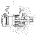
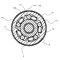
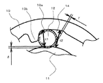
図1は実施の形態1に係るエンジン始動装置の断面図、図2は図1のII−II線に沿った矢視断面図、図3は図2のローラ12によるクラッチインナ11への噛み込みを示す図である。
実施の形態1に係るエンジン始動装置は、モータ1と、図示しないキースイッチの操作により、モータ1への通電を入り切りするスイッチ2と、モータ1の回転軸1aに減速部3を介して設けられ、回転軸1aからの回転力が伝達される出力軸4と、この出力軸4に設けられ、軸線方向に沿って摺動可能なクラッチ5と、このクラッチ5に設けられ、エンジンのリングギヤ6と歯合可能なピニオンギヤ7と、出力軸4、クラッチ5およびピニオンギヤ7を覆ったハウジング8とを備えている。
1 is a cross-sectional view of the engine starting device according to the first embodiment, FIG. 2 is a cross-sectional view taken along the line II-II in FIG. 1, and FIG. FIG.
The engine starter according to
減速部3は、モータ1の回転軸1aの先端部に固定され、回転軸1aに同期して回転する太陽歯車3aと、出力軸4のモータ1側に形成されたフランジ部4aに固定されたピン9により回転自在に支持され、太陽歯車3aに歯合した遊星歯車3bと、ハウジング8に固定され、遊星歯車3bと歯合した樹脂製の内歯歯車3cとを有している。
The speed reducer 3 is fixed to the tip of the rotating shaft 1a of the
クラッチ5は、出力軸4に係合し、出力軸4と同期して回転する円筒形状のクラッチアウタ10と、クラッチアウタ10に回転可能に設けられ、一端部がクラッチアウタ10の内部に臨み、他端部の外周面にピニオンギヤ7が固定された円筒形状のクラッチインナ11と、クラッチアウタ10の内周面とクラッチインナ11の外周面との間に設けられ、周方向に沿って転動可能なローラ12と、端部がローラ12に接続されたバネ13とを有している。
The clutch 5 is engaged with the output shaft 4, is provided in a cylindrical shape with a clutch outer 10 that rotates in synchronization with the output shaft 4, and is rotatably provided on the clutch outer 10. One end of the clutch 5 faces the inside of the clutch outer 10, A cylindrical clutch inner 11 having a pinion gear 7 fixed to the outer peripheral surface of the other end portion is provided between the inner peripheral surface of the clutch outer 10 and the outer peripheral surface of the clutch inner 11, and can roll along the circumferential direction. And a
クラッチアウタ10の反モータ1側端部には、ローラ12およびバネ13の軸線方向の移動を規制するプレート15が設けられ、このプレート15とクラッチアウタ10とに渡って、外側からプレート15を固定するカバー16が設けられている。
A
クラッチアウタ10のモータ1側端部には、モータ1側の径が大きくなった遊動環17が止め輪18により固定されている。
スイッチ2には、回動軸19aを中心に回動可能なシフトレバー19が設けられており、このシフトレバー19の先端部が遊動環17およびクラッチアウタ10の底面と係合している。スイッチ2の作動により、シフトレバー19が回動すると、クラッチ5が出力軸4に沿って摺動する。
An
The switch 2 is provided with a
ローラ12は、JIS G 4805の高炭素クロム軸受鋼(SUJ2)から構成されている。なお、ローラ12はその他の材料から構成されてもよい。
The
クラッチアウタ10の内周面には、周方向に沿ってテーパ形状の切り欠き部10aが形成され、クラッチアウタ10の内周面とクラッチインナ11外周面との間には、狭小側の幅がt1であり、広大側の幅がt1より大きいt2である楔形空間14が形成されている。
楔形空間14の狭小側の切り欠き部10aには、ローラ12と当接可能な係止部10bが形成され、バネ13がローラ12を係止部10b側に向かって付勢可能である。
楔形空間14内には、潤滑のために図示しないグリスが充填されており、プレート15がグリスの漏出を防止している。
A taper-
A
The wedge-
ローラ12の転動面には、全周に渡って浸炭窒化処理がされており、摩擦熱による硬度の低下が抑制されている。
ローラ12の転動面の浸炭窒化処理がされた有効深さγは、ローラ12が係止部10bに当接した場合の、クラッチインナ11へのローラ12の噛み込み深さδより大きく形成されている。
The rolling surface of the
The effective depth γ of which the rolling surface of the
クラッチアウタ10が一方向に回転すると、ローラ12が楔形空間14の狭小側へ移動し、クラッチアウタ10の内周面およびクラッチインナ11の外周面にローラ12が噛み込むことでクラッチアウタ10とクラッチインナ11が固定されて、クラッチアウタ10の回転力がクラッチインナ11に伝達される。
さらに大きな回転力がクラッチアウタ10に加えられると、ローラ12がクラッチアウタ10の内周面およびクラッチインナ11の外周面にさらに深く噛み込むものの、ローラ12が係止部10bに当接することで、ローラ12とクラッチインナ11の外周面との間で滑りが発生し、それ以上の回転力の伝達が遮断される。
このときの、クラッチアウタ10からクラッチインナ11へ伝達される最大の回転力である伝達限界トルクの大きさは、ローラ12が係止部10bに当接したときのクラッチインナ11へのローラ12の噛み込み深さδによって決定される。
したがって、伝達限界トルクの大きさが、リングギヤ6を回転させる際に必要なトルクより大きく、リングギヤ6のねじり強度よりも小さくなるように、噛み込み深さδが設定される。
When the clutch outer 10 rotates in one direction, the
When a larger rotational force is applied to the clutch outer 10, the
The magnitude of the transmission limit torque, which is the maximum rotational force transmitted from the clutch outer 10 to the clutch inner 11 at this time, is such that the
Therefore, the biting depth δ is set so that the magnitude of the transmission limit torque is larger than the torque necessary for rotating the
浸炭窒化処理がされたローラ12の転動面の表面硬度は、Hv600以上、かつ、Hv900以下となっている。
これにより、ローラ12の転動面の磨耗を抑制するとともに、ローラ12の転動面の剥離の発生を抑制することができる。
The surface hardness of the rolling surface of the
Thereby, wear of the rolling surface of the
次に、実施の形態1に係るエンジン始動装置の動作について説明する。
まず、キースイッチの操作により、スイッチ2が作動してモータ1に通電するとともに、シフトレバー19を回動させる。
通電されたモータ1が回転軸1aを回転させて、この回転力が減速部3を介して出力軸4に伝達される。
出力軸4が一方向に回転し、クラッチアウタ10が出力軸4と同期して一方向に回転すると、ローラ12が楔形空間14の狭小側に移動して、ローラ12がクラッチアウタ10の内周面およびクラッチインナ11の外周面に噛み込む。
ローラ12がクラッチアウタ10の内周面およびクラッチインナ11の外周面に噛み込むことによりクラッチアウタ10とクラッチインナ11が固定される。
クラッチアウタ10に固定されたクラッチインナ11は、クラッチアウタ10からの回転力が伝達され、その回転力をピニオンギヤ7に伝達する。
一方、シフトレバー19の回動により、クラッチ5が軸線方向に沿って反モータ1側に摺動するので、ピニオンギヤ7がエンジンのリングギヤ6と歯合し、ピニオンギヤ7からリングギヤ6に回転力が伝達される。
Next, the operation of the engine starter according to Embodiment 1 will be described.
First, by operating the key switch, the switch 2 is activated to energize the
The
When the output shaft 4 rotates in one direction and the clutch outer 10 rotates in one direction in synchronization with the output shaft 4, the
When the
The clutch inner 11 fixed to the clutch outer 10 receives the rotational force from the clutch outer 10 and transmits the rotational force to the pinion gear 7.
On the other hand, as the shift lever 19 rotates, the clutch 5 slides in the direction opposite to the
エンジンが始動した後、エンジンの回転によるリングギヤ6の回転速度が出力軸4の回転速度より速くなると、クラッチアウタ10がクラッチインナ11に対して他方向に回転する。
クラッチアウタ10がクラッチインナ11に対して他方向に回転すると、ローラ12が楔形空間14の狭小側から広大側へ移動して、クラッチアウタ10とクラッチインナ11との固定が解除される。
クラッチアウタ10とクラッチインナ11との固定が解除されることにより、エンジンの回転力がモータ1を連れまわすことが回避され、過回転によるモータ1の破損を防止する。
キースイッチを元の状態に戻すと、シフトレバー19が逆方向に回動して、エンジンのリングギヤ6とピニオンギヤ7との歯合が解除される。
After the engine is started, when the rotation speed of the
When the clutch outer 10 rotates in the other direction with respect to the clutch inner 11, the
By releasing the fixation of the clutch outer 10 and the clutch inner 11, it is avoided that the rotational force of the engine carries the
When the key switch is returned to the original state, the
キースイッチを操作しても、エンジンが始動しなかった場合には、キースイッチを元の状態に戻して、エンジンのリングギヤ6とピニオンギヤ7との歯合を解除する。
このとき、ピニオンギヤ7は惰性で回転し、エンジンのリングギヤ6は正回転と逆回転とを繰り返している。
再度、キースイッチを操作したときに、エンジンが逆回転している場合には、リングギヤ6とピニオンギヤ7とが互いに逆方向に回転しているので激しく衝突する。
リングギヤ6とピニオンギヤ7との激しい衝突により、クラッチ5のローラ12が、楔形空間14の狭小側へ移動し、クラッチアウタ10の内周面およびクラッチインナ11の外周面に噛み込み、係止部10bに衝突する。
ローラ12は、楔形空間14の狭小側へさらに移動しようとするものの、係止部10bにより狭小側への移動が規制されるので、ローラ12のクラッチインナ11の外周面への噛み込み量が所定の噛み込み量δに抑えられている。
If the engine does not start even when the key switch is operated, the key switch is returned to the original state, and the engagement between the
At this time, the pinion gear 7 rotates by inertia and the
When the key switch is operated again and the engine is rotating in the reverse direction, the
Due to a violent collision between the
Although the
ローラ12のクラッチインナ11の外周面への噛み込み量が所定の噛み込み量δに抑えられているので、この噛み込み量δによる摩擦力より大きい回転力でクラッチアウタ10が回転すると、ローラ12の転動面とクラッチインナ11の外周面との間に滑りが発生し、ローラ12の転動面とクラッチインナ11の外周面との間には摩擦熱が発生する。
しかしながら、ローラ12の転動面には、浸炭窒化処理が行われているので、摩擦熱によるローラ12の転動面の軟化が低減される。
その結果、ローラ12の転動面とクラッチインナ11の外周面との間に滑りが発生しても、ローラ12の転動面における硬度の低下を抑制することができる。
Since the engagement amount of the
However, since the rolling surface of the
As a result, even if slip occurs between the rolling surface of the
以上説明したように、実施の形態1に係るエンジン始動装置によると、ローラ12の転動面には、浸炭窒化処理がされているので、ローラ12の転動面がクラッチインナ11の外周面に対して滑りが発生することでローラの転動面に摩擦熱が発生しても、この摩擦熱によるローラ12の転動面における硬度の低下を抑制することでローラ12の転動面の変形を低減して、クラッチアウタ10からクラッチインナ11への回転力の伝達を向上させることができる。
As described above, according to the engine starter according to the first embodiment, since the rolling surface of the
また、ローラ12の転動面の浸炭窒化処理がされた有効深さγは、ローラ12が係止部10bに当接した場合における、クラッチインナ11へのローラ12の噛み込み量δより大きいので、ローラ12はクラッチインナ11との噛み込み量がなくなるまで磨耗しても、摩擦熱によるローラ12の転動面における硬度の低下を抑制することができる。
Further, the effective depth γ of the rolling contact surface of the
なお、上記実施の形態1では、切り欠き部10aおよび係止部10bがクラッチアウタ10に形成されたクラッチ5について説明したが、勿論このものに限らず、切り欠き部および係止部がクラッチインナ11に形成されたクラッチ5であってもよい。
In the first embodiment, the clutch 5 in which the
また、上記実施の形態1では、モータ1の回転軸1aに減速部3を介して出力軸4が設けられたエンジン始動装置について説明したが、勿論このものに限らず、モータ1の回転軸1aに直結して出力軸4が設けられたエンジン始動装置であってもよい。
Further, in the first embodiment, the engine starting device in which the output shaft 4 is provided on the rotating shaft 1a of the
1 モータ、1a 回転軸、2 スイッチ、3 減速部、3a 太陽歯車、3b 遊星歯車、3c 内歯歯車、4 出力軸、4a フランジ部、5 クラッチ、6 リングギヤ、7 ピニオンギヤ、8 ハウジング、9 ピン、10 クラッチアウタ、10a 切り欠き部、10b 係止部、11 クラッチインナ、12 ローラ、13 バネ、14 楔形空間、15 プレート、16 カバー、17 遊動環、18 止め輪、19 シフトレバー、19a 回動軸。 1 motor, 1a rotating shaft, 2 switch, 3 reduction gear, 3a sun gear, 3b planetary gear, 3c internal gear, 4 output shaft, 4a flange, 5 clutch, 6 ring gear, 7 pinion gear, 8 housing, 9 pin, 10 Clutch outer, 10a Notch portion, 10b Locking portion, 11 Clutch inner, 12 Roller, 13 Spring, 14 Wedge-shaped space, 15 Plate, 16 Cover, 17 Free ring, 18 Retaining ring, 19 Shift lever, 19a Rotating shaft .
Claims (2)
前記出力軸に摺動可能に設けられ、前記出力軸の一方向の回転力を伝達するクラッチと、
前記クラッチに設けられ、リングギヤと歯合するピニオンギヤとを備え、
前記クラッチは、
底部が前記出力軸に係合し、前記出力軸と同期して回転する有底円筒形状のクラッチアウタと、
前記クラッチアウタに回転可能に設けられ、一端部が前記クラッチアウタの内側に臨み、他端部の外周面に前記ピニオンギヤが設けられた円筒形状のクラッチインナと、
前記クラッチアウタと前記クラッチインナとの間に設けられ、転動面を含み、周方向に沿って転動可能なローラとを有し、
前記クラッチアウタの内周面または前記クラッチインナの外周面の何れか一方には、周方向に沿ってテーパ形状の切り欠き部が形成され、
前記クラッチアウタと前記クラッチインナとにより区画された楔形空間の狭小側の前記切り欠き部には、径方向に沿って突出し、前記ローラと当接可能な係止部が形成されたエンジン始動装置において、
前記ローラの前記転動面には、浸炭窒化処理がされていることを特徴とするエンジン始動装置。 An output shaft connected to the rotation shaft of the motor and rotated by driving the motor;
A clutch that is slidably provided on the output shaft, and transmits a rotational force in one direction of the output shaft;
A pinion gear provided on the clutch and meshing with the ring gear;
The clutch is
A bottomed cylindrical clutch outer whose bottom part engages with the output shaft and rotates in synchronization with the output shaft;
A cylindrical clutch inner provided rotatably on the clutch outer, with one end facing the inside of the clutch outer and the pinion gear provided on the outer peripheral surface of the other end;
A roller provided between the clutch outer and the clutch inner, including a rolling surface and capable of rolling along a circumferential direction;
A taper-shaped notch is formed along the circumferential direction on either the inner peripheral surface of the clutch outer or the outer peripheral surface of the clutch inner.
In the engine starting device, the notch portion on the narrow side of the wedge-shaped space defined by the clutch outer and the clutch inner is formed with a locking portion that protrudes along the radial direction and can come into contact with the roller. ,
An engine starter characterized in that the rolling surface of the roller is carbonitrided.
Priority Applications (2)
| Application Number | Priority Date | Filing Date | Title |
|---|---|---|---|
| JP2007135391A JP4330023B2 (en) | 2007-05-22 | 2007-05-22 | Engine starter |
| US11/943,978 US8418571B2 (en) | 2007-05-22 | 2007-11-21 | Engine starter |
Applications Claiming Priority (1)
| Application Number | Priority Date | Filing Date | Title |
|---|---|---|---|
| JP2007135391A JP4330023B2 (en) | 2007-05-22 | 2007-05-22 | Engine starter |
Publications (2)
| Publication Number | Publication Date |
|---|---|
| JP2008291663A true JP2008291663A (en) | 2008-12-04 |
| JP4330023B2 JP4330023B2 (en) | 2009-09-09 |
Family
ID=40071155
Family Applications (1)
| Application Number | Title | Priority Date | Filing Date |
|---|---|---|---|
| JP2007135391A Expired - Fee Related JP4330023B2 (en) | 2007-05-22 | 2007-05-22 | Engine starter |
Country Status (2)
| Country | Link |
|---|---|
| US (1) | US8418571B2 (en) |
| JP (1) | JP4330023B2 (en) |
Families Citing this family (3)
| Publication number | Priority date | Publication date | Assignee | Title |
|---|---|---|---|---|
| WO2012131973A1 (en) * | 2011-03-31 | 2012-10-04 | 三菱電機株式会社 | Engine starting device |
| JP6232692B2 (en) * | 2012-09-24 | 2017-11-22 | 株式会社ジェイテクト | Torque limiter, windmill and wind power generator |
| CN116498472B (en) * | 2023-05-05 | 2025-07-01 | 钛盛(福建省)机电科技有限公司 | Friction shoe assembly, engine pull-free starter and engine |
Family Cites Families (10)
| Publication number | Priority date | Publication date | Assignee | Title |
|---|---|---|---|---|
| JPS5926107Y2 (en) | 1979-12-28 | 1984-07-30 | 三菱電機株式会社 | overrunning clutch |
| JPH07113383B2 (en) | 1993-09-30 | 1995-12-06 | 三菱電機株式会社 | Overrunning clutch manufacturing method |
| US5848846A (en) * | 1996-07-26 | 1998-12-15 | Ntn Corporation | Shell type needle roller bearing and method of producing the same |
| JP2001074053A (en) * | 1999-04-01 | 2001-03-23 | Nsk Ltd | Rolling bearing |
| JP3499156B2 (en) * | 1999-06-07 | 2004-02-23 | 三菱電機株式会社 | Starter |
| DE10020118B4 (en) * | 2000-04-22 | 2009-11-12 | Schaeffler Kg | Method for verifying sealability of selected exhaust valve of selected cylinder in internal combustion engine in motor vehicle, involves concluding sealability of valve based on measured values of lambda sensor in one of exhaust gas strands |
| JP3584921B2 (en) | 2001-10-04 | 2004-11-04 | 日本精工株式会社 | Corrosion resistant rolling bearing |
| JP2004293632A (en) * | 2003-03-26 | 2004-10-21 | Ntn Corp | Rolling bearing |
| JP2006300167A (en) | 2005-04-19 | 2006-11-02 | Nsk Ltd | One-way clutch built-in type rotation transmission device |
| DE112006003545B4 (en) | 2005-12-28 | 2018-05-17 | Mitsuba Corp. | Engine starter |
-
2007
- 2007-05-22 JP JP2007135391A patent/JP4330023B2/en not_active Expired - Fee Related
- 2007-11-21 US US11/943,978 patent/US8418571B2/en not_active Expired - Fee Related
Also Published As
| Publication number | Publication date |
|---|---|
| US8418571B2 (en) | 2013-04-16 |
| JP4330023B2 (en) | 2009-09-09 |
| US20080289446A1 (en) | 2008-11-27 |
Similar Documents
| Publication | Publication Date | Title |
|---|---|---|
| EP3026298A1 (en) | Pulley device with embedded unidirectional clutch | |
| US4989704A (en) | Overrunning clutch | |
| CN105680619A (en) | Motor assembly and vehicle starter | |
| US8511186B2 (en) | Engine starter | |
| JP2009103248A (en) | transmission | |
| JP4330023B2 (en) | Engine starter | |
| JP3843960B2 (en) | Starter | |
| JP4572912B2 (en) | Starter | |
| US20130074652A1 (en) | Starter Motor Having Clutch with Grooved Roller Elements | |
| JP5129577B2 (en) | Engine starter | |
| JP2009085408A (en) | Engine starter | |
| JP2008082186A (en) | Torque transmission device for engine start | |
| US5520273A (en) | Over-running clutch | |
| JP2009097442A (en) | Starter | |
| US20100025176A1 (en) | Power transmission apparatus | |
| JP2003214528A (en) | One-way clutch integrated rotation transmission device for starter motor | |
| JP2009047075A (en) | Engine starter | |
| JP3555539B2 (en) | Shock absorber | |
| JP5022698B2 (en) | Engine starter | |
| KR20130017867A (en) | Power transmission apparatus of starter motor for the vehicle engine | |
| JP2007297966A (en) | Starter device for vehicle | |
| JP5022699B2 (en) | Engine starter | |
| CN206545564U (en) | The little gear detent mechanism and starter of a kind of starter | |
| JP3501312B2 (en) | One-way clutch | |
| JP4532451B2 (en) | Engine starter |
Legal Events
| Date | Code | Title | Description |
|---|---|---|---|
| A977 | Report on retrieval |
Free format text: JAPANESE INTERMEDIATE CODE: A971007 Effective date: 20090213 |
|
| A131 | Notification of reasons for refusal |
Free format text: JAPANESE INTERMEDIATE CODE: A131 Effective date: 20090303 |
|
| A521 | Request for written amendment filed |
Free format text: JAPANESE INTERMEDIATE CODE: A523 Effective date: 20090428 |
|
| TRDD | Decision of grant or rejection written | ||
| A01 | Written decision to grant a patent or to grant a registration (utility model) |
Free format text: JAPANESE INTERMEDIATE CODE: A01 Effective date: 20090602 |
|
| A01 | Written decision to grant a patent or to grant a registration (utility model) |
Free format text: JAPANESE INTERMEDIATE CODE: A01 |
|
| A61 | First payment of annual fees (during grant procedure) |
Free format text: JAPANESE INTERMEDIATE CODE: A61 Effective date: 20090611 |
|
| R150 | Certificate of patent or registration of utility model |
Free format text: JAPANESE INTERMEDIATE CODE: R150 Ref document number: 4330023 Country of ref document: JP Free format text: JAPANESE INTERMEDIATE CODE: R150 |
|
| FPAY | Renewal fee payment (event date is renewal date of database) |
Free format text: PAYMENT UNTIL: 20120626 Year of fee payment: 3 |
|
| FPAY | Renewal fee payment (event date is renewal date of database) |
Free format text: PAYMENT UNTIL: 20130626 Year of fee payment: 4 |
|
| R250 | Receipt of annual fees |
Free format text: JAPANESE INTERMEDIATE CODE: R250 |
|
| R250 | Receipt of annual fees |
Free format text: JAPANESE INTERMEDIATE CODE: R250 |
|
| R250 | Receipt of annual fees |
Free format text: JAPANESE INTERMEDIATE CODE: R250 |
|
| R250 | Receipt of annual fees |
Free format text: JAPANESE INTERMEDIATE CODE: R250 |
|
| R250 | Receipt of annual fees |
Free format text: JAPANESE INTERMEDIATE CODE: R250 |
|
| R250 | Receipt of annual fees |
Free format text: JAPANESE INTERMEDIATE CODE: R250 |
|
| R250 | Receipt of annual fees |
Free format text: JAPANESE INTERMEDIATE CODE: R250 |
|
| LAPS | Cancellation because of no payment of annual fees |